THARMAC Cellspin II User manual

Instruction manual
Cellspin® II / Cellspin® IIR
Cytocentrifuge
Man CS2/CS2R 01.2017 EN

THARMAC® GmbH - Cellspin® II/IIR - Instruction
manual
Contact:
THARMAC® GmbH
Hasselborner Straße 19-21
35647 Waldsolms
Germany
Fon:
+49-(0)6085 - 98 99 10
Fax:
+49-(0)6085 - 98 99 119
www.tharmac.de
THARMAC® GmbH
Borsigstraße 7A
65205 Wiesbaden
Germany
Fon:
+49-(0)6122 - 588 97 33
Fax:
+49-(0)6122 - 588 97 36
www.tharmac.de
Cellspin®, Cellfunnel® and TPX-Funnel®, ECOfunnel® and GynoPrep® are registered trademarks.

THARMAC® GmbH - Cellspin® II/IIR - Instruction
manual
Table of contents
1Use according to specification ......................................................................................................... 5
2Remaining risks..................................................................................................................................... 5
3Technical specifications ..................................................................................................................... 5
4Notes on safety.................................................................................................................................... 7
5Symbol meanings ................................................................................................................................ 9
6Delivery checklist................................................................................................................................. 9
7Unpacking the centrifuge.................................................................................................................. 9
8Initial operation.................................................................................................................................. 10
9Opening and closing the lid ............................................................................................................ 10
Opening the lid ........................................................................................................................................... 10
Closing the lid .............................................................................................................................................. 10
10 Installation and removal of the rotor .............................................................................................. 11
11 Loading the rotor............................................................................................................................... 11
12 Control and display elements ......................................................................................................... 11
Control knob................................................................................................................................................ 11
Control panel pushbuttons (keys) ............................................................................................................ 11
Adjustment possibilities............................................................................................................................... 12
13 Entering centrifugation parameter ................................................................................................ 12
14 Programming ..................................................................................................................................... 13
Program input/alteration ........................................................................................................................... 13
Program recall............................................................................................................................................. 13
15 Centrifugation ................................................................................................................................... 13
Centrifugation with pre-set time............................................................................................................... 13
Continuous run ............................................................................................................................................ 14
Short-term centrifugation........................................................................................................................... 14
16 Emergency Stop................................................................................................................................ 15
17 Acoustic Signal .................................................................................................................................. 15
18 Cooling (only in centrifuges with cooling)..................................................................................... 15
Standby-cooling ......................................................................................................................................... 15
Pre-cooling the rotor .................................................................................................................................. 15
19 Relative centrifugal force (RCF)...................................................................................................... 16
20 Centrifugation of materials or mixtures of materials with a density higher than 1.2 kg/dm3. 16
21 Rotor Identification ........................................................................................................................... 16
22 Emergency release........................................................................................................................... 17
23 Maintenance and servicing ............................................................................................................ 17
Centrifuge (housing, lid and centrifuging chamber) ............................................................................ 17
Surface cleaning and care................................................................................................................. 17

THARMAC® GmbH - Cellspin® II/IIR - Instruction
manual
Surface disinfection.............................................................................................................................. 17
Removal of radioactive contaminants ............................................................................................. 18
Rotors and Attachments............................................................................................................................ 18
Cleaning and care............................................................................................................................... 18
Disinfection .................................................................................................................................................. 18
Removal of radioactive contaminants ............................................................................................. 19
Trunnions ................................................................................................................................................ 19
Rotors and accessories with limited service lives ............................................................................. 19
Autoclaving ................................................................................................................................................. 19
Centrifuge containers ................................................................................................................................ 19
24 Faults ................................................................................................................................................... 20
25 Acceptance of the centrifuges for repair..................................................................................... 21
26 Disposal............................................................................................................................................... 21
27 Introduction........................................................................................................................................ 22
28 Assembling and disassembling of Cellfunnel® preparation system .......................................... 23
29 Assembling and disassembling of the ECOfunnel® preparation system.................................. 26
30 Cleaning reusable Cellfunnel® or ECOfunnel® and CellClips .................................................. 29
31 Installation and removal of rotor hub (E) ....................................................................................... 30
Removable rotor 370 .................................................................................................................................. 31
Closed CellClip-rotor 101 ........................................................................................................................... 32
Cleaning the closed CellClip-rotor ........................................................................................................... 34
32 Application field for Cellspin® Cytocentrifuge ............................................................................ 36
33 Instruction for processing of different body fluids with Cellspin® Cytocentrifuge................... 37
34 Additional information...................................................................................................................... 43
35 Prevention of inaccurate results ..................................................................................................... 44
36 Recommended times and speed .................................................................................................. 45
37 Declaration of conformity................................................................................................................ 47
38 Conversion table............................................................................................................................... 48
39 Consumables for Cellspin® Cytocentrifuge ................................................................................ 49

THARMAC® GmbH - Cellspin® II/IIR - Instruction
manual
THARMAC® GmbH - Cellspin® II/IIR - Instruction
manual
1 Use according to specification
The machine presented here is a medical product (laboratory centrifuge) according to the IVD guideline 98/79/EG.
The centrifuge is used to separate substances or substance mixtures with a density of max. 1.2 kg/dm³. This also
includes substances and substance mixtures of human origin. The centrifuge is only intended to be used for this
purpose. A different use or application over and above this is deemed not in accordance with the specifications. The
company THARMAC Cellspin® GmbH undertakes no liability for damages resulting therefrom.
Belonging to the application according to specification is also the observance of all references contained in the
Instruction Manual and compliance with the inspection and maintenance works.
2 Remaining risks
The device is built according to the state-of-the-art and the recognized safety regulations. If used and handled
improperly, there could be life-threatening danger to the user or third parties, or the device could be impaired or there
could be other property damage. The device is only to be used for its intended purpose and only when it is in safe
working condition.
Malfunctions which could affect safety must be corrected immediately.
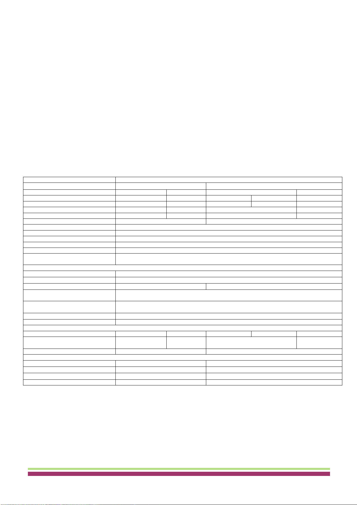
3 Technical specifications
Manufacturer
THARMAC® GmbH, D-35647 Waldsolms
Model
Cellspin® II
Cellspin® IIR
Type
1401
1401-01
1406
1406-01
Mains voltage (+/- 10%)
200-240 V 1~
100-127 V 1~
200-240 V 1~
240 V 1~
115-127 V 1~
Mains frequency
50-60 Hz
50-60 Hz
50 Hz
60 Hz
60 Hz
Connected load
400 VA
400 VA
800 VA
950 VA
Current consumption
2.0 A
4.0 A
4.0 A
8.0 A
Cooling medium
-
R 404A
Max. capacity
4x 200 ml
Allowed density
1.2 kg/dm³
Speed (RPM)
16000
Force (RCF)
24900
Kinetic force
9500 Nm
Obligatory inspection (DGUV Regel
100-500)
No
Ambient conditions (EN/IEC 61010-1)
- Set-up site
Indoors only
- Altitude
Up to 2000 m above sea level
- Ambient temperature
2 °C to 35 °C
5 °C to 35 °C
- Humidity
Maximum relative humidity 80% for temperatures up to 31 °C, linearly decreasing to 50% relative
humidity at 40 °C
- Excess-voltage category (IEC
60364-4-443)
II
- Pollution degree
2
Device protection class
I
Not suitable for use in explosion-endangered areas
EMC
- Emitted interference,
Interference immunity
EN / IEC 61326-1,
Class B
FCC Class B
EN / IEC 61326-1, Class B
Class B
Noise level (dependent on rotor)
≤ 68 dB(A)
≤ 64 dB(A)
Dimensions
- Width
401 mm
407 mm
- Depth
529 mm
698 mm
- Height
346 mm
346 mm
Weight
Approx. 31 kg
Approx. 52 kg
5

THARMAC® GmbH - Cellspin® II/IIR - Instruction
manual
Manufacturer
THARMAC® GmbH, D-35647 Waldsolms
Model
Cellspin® IIR
Type
1406-50
1406-51
1406-70
1406-71
Mains voltage (+/- 10%)
200-240 V 1~
100-127 V 1~
200-240 V 1~
115-127 V 1~
Mains frequency
50-60 Hz
50-60 Hz
50 - 60 Hz
50 - 60 Hz
Connected load
400 VA
400 VA
400 VA
400 VA
Current consumption
2.0 A
4.0 A
2.0 A
4.0 A
Cooling medium
R 404A
Max. capacity
4x 200 ml
Allowed density
1.2 kg/dm³
Speed (RPM)
16000
Force (RCF)
24900
Kinetic force
9500 Nm
Obligatory inspection (DGUV Regel
100-500)
No
Ambient conditions (EN/IEC 61010-1)
- Set-up site
Indoors only
- Altitude
Up to 2000 m above sea level
- Ambient temperature
2 °C to 35 °C
- Humidity
Maximum relative humidity 80% for temperatures up to 31 °C, linearly decreasing to 50% relative
humidity at 40 °C
- Excess-voltage category (IEC
60364-4-443)
II
- Pollution degree
2
Device protection class
I
Not suitable for use in explosion-endangered areas
EMC
- Emitted interference,
Interference immunity
EN / IEC 61326-1,
Class B
FCC Class B
EN / IEC 61326-1, Class B
Class B
Noise level (dependent on rotor)
≤ 64 dB(A)
Dimensions
- Width
401 mm
407 mm
- Depth
529 mm
698 mm
- Height
346 mm
346 mm
Weight
Approx. 35 kg
Manufacturer
THARMAC® GmbH, D-35647 Waldsolms
Model
Cellspin® IIR
Type
1406-20
1406-21
Mains voltage (+/- 10%)
200-240 V 1~
240 V 1~
115-127 V 1~
Mains frequency
50 Hz
60 Hz
60 Hz
Connected load
800 VA
950 VA
Current consumption
4.0 A
8.0 A
Cooling medium
R 404A
Max. capacity
4x 200 ml
Allowed density
1.2 kg/dm³
Speed (RPM)
16000
Force (RCF)
24900
Kinetic force
9500 Nm
Obligatory inspection (DGUV Regel
100-500)
No
Ambient conditions (EN/IEC 61010-1)
- Set-up site
Indoors only
- Altitude
Up to 2000 m above sea level
- Ambient temperature
2 °C to 35 °C
- Humidity
Maximum relative humidity 80% for temperatures up to 31 °C, linearly decreasing to 50% relative
humidity at 40 °C
- Excess-voltage category (IEC
60364-4-443)
II
- Pollution degree
2
Device protection class
I
Not suitable for use in explosion-endangered areas
EMC
- Emitted interference,
Interference immunity
EN / IEC 61326-1, Class B
Class B
Noise level (dependent on rotor)
≤ 64 dB(A)
Dimensions
- Width
407 mm
- Depth
725 mm
- Height
356 mm
Weight
Approx. 52 kg

THARMAC® GmbH - Cellspin® II/IIR - Instruction
manual
4 Notes on safety
Before the initial operation of your centrifuge you should read and pay attention to the operating
instructions. Only personnel that has read and understood the operating instructions are allowed to
operate the device.
Along with the operating instructions and the legal regulations on accident prevention, you should also follow the
recognized professional regulations for working in a safe and professional manner. These operating instructions
should be read in conjunction with any other instructions concerning accident prevention and environmental
protection based on the national regulations of the country where the device is to be used.
This centrifuge is a state-of-the-art piece of equipment which is extremely safe to operate. However, it can lead to
danger for users or others if used by untrained staff, in an inappropriate way or for a purpose other than that it
was designed for.
The centrifuge must not be moved or knocked during operation.
In case of fault or emergency release, never touch the rotor before it has stopped turning.
To avoid damage due to condensate, when changing from a cold to a warm room the centrifuge must either heat
up for at least 3 hours in the warm room before being connected to the mains, or run hot for 30 minutes in the
cold room.
The centrifuge rotor may only be loaded in accordance with the chapter "Loading the rotor".
When centrifuging with maxim revolutions per minute the density of the materials or the material mixtures may not
exceed 1.2 kg/dm3.
The centrifuge may only be operated when the balance is within the bounds of acceptability.
The centrifuge may not be operated in explosion-endangered areas.
The centrifuge must not be used with:
inflammable or explosive materials
materials that react with one another producing a lot of energy.
7
The centrifuge should be installed on a good, stable base.
Before using the centrifuge absolutely check the rotor for firm placement.
When the centrifuge is running, according to EN / IEC 61010-2-020, no persons, dangerous
substances or objects may be within the safety margin of 300 mm around the centrifuge.
Rotors, suspensions and accessories that possess traces of corrosion or mechanical damage or
if their term of use has expired may not be used any longer.
The centrifuge may no longer be put into operation when the centrifuging chamber has safety-
related damages.
With swing-out rotors the trunnions must be regularly lubricated in order to ensure
consistent swinging out of the hangers.
For centrifuges without temperature control, when the room temperature is increased and/or if the
device is frequently used, the centrifuging chamber could be heated up. Therefore, it can't be
ruled out that the sample material might be changed due to the temperature.
No claim of warranty will be considered by the manufacturer unless ALL instructions in this manual
have been followed.

THARMAC® GmbH - Cellspin® II/IIR - Instruction
manual
When centrifuging hazardous substances or mixtures, which are toxic, radioactive or contaminated with pathogenic
microorganisms, suitable measures must be taken by the user. Fundamentally, centrifuge containers with special screw
closures must be used for hazardous substances. For materials of risk groups 3 and 4, in addition to sealable centrifuge
containers, a bio-safety system must be used (see the "Laboratory Bio-safety Manual" from the World Health Organization).
In a bio-safety system, a bio-seal (sealing ring) prevents droplets and aerosols from escaping. If the hanger of a bio-safety
system is used without the lid, the sealing ring must be removed from the hanger to prevent damage to the sealing ring
during the centrifugation run. Damaged bio-safety systems are no longer microbiologically sealed.
If a bio-safety system is not used, a centrifuge is not microbiologically sealed for the purposes of the standard EN / IEC
61010-2-020.
When closing a bio-safety system, follow the instructions in the chapter "Handling of bio-safety systems".
For the available bio-safety systems, see the chapter "Appendix, Rotors and accessories". If in doubt, you can get the
information you need from the manufacturer..
The centrifuge must not be operated with highly corrosive substances which could impair the mechanical integrity
of rotors, hangers and accessories.
Repairs must only be carried out by personnel authorized to do so by the manufacturer.
Only original spare parts and original accessories licensed by THARMAC® GmbH.
The following safety regulations apply:
EN / IEC 61010-1 and EN / IEC 61010-2-020 as well as their national deviations.
The safe operation and reliability of the centrifuge can only be guaranteed if:
the centrifuge is operated in accordance with the operating instructions,
the electrical installation on the site where the centrifuge is installed conforms to the demands of EN / IEC
stipulations,
the tests for device safety required in the respective countries, e.g. in Germany in acc. with BGV A1 and BGR
500, are carried out by an expert.
8
THARMAC® GmbH - Cellspin® II/IIR - Instruction
manual
5 Symbol meanings
Symbol on the device:
Attention, general hazard area.
Before using the device, make sure you read the operating instructions and observe the safety
information!
Symbol in this document:
Attention, general hazard area.
This symbol refers to safety relevant warnings and indicates possibly dangerous situations.
The non-adherence to these warnings can lead to material damage and injury to personal.
Symbol on the device and in this document:
Beware of biohazard.
Symbol in this document:
This symbol refers to important circumstances.
Symbol on the device and in this document:
Symbol for the separate collection of electric and electronic devices according to the guideline
2002/96/EG (WEEE). The device belongs to Group 8 (medical devices).
Applies in the countries of the European Union, as well as in Norway and Switzerland.
6 Delivery checklist
The following items and accessories are delivered with the centrifuge:
1Connecting cable
1 Hex. pin driver
1Notes on moving the equipment safely
1Operating instructions
1Lubricating grease for trunnions
The rotor(s) and associated accessories are included in the delivery in the quantity.
7 Unpacking the centrifuge
Lift the carton upward and remove the padding.
Lift the centrifuge on both sides with an appropriate number of helpers and place it on the laboratory table.
9
Do not lift by the handle rail.
Observe the weight of the centrifuge, refer to chapter "Technical specifications".

THARMAC® GmbH - Cellspin® II/IIR - Instruction
manual
8 Initial operation
Remove the transportation safety device from the bottom of the housing, see sheet ”Transportation safety device"
Position the centrifuge in a stable and level manner in a suitable place. During set-up, the required safety margin of
300 mm around the centrifuge is to be kept according to EN / IEC 61010-2-020.
Ventilation openings may not be blocked.
A distance of 300 mm must be maintained from the ventilation slots and openings of the centrifuge.
In the case of the centrifuge, type 1406-20, 1406-21, connect the nitrogen supply according to the enclosed instruction sheet
AH1406-20XX.
In the case of the centrifuge, type 1406-50, 1406-51, connect the refrigerating/heating circulator according to the enclosed
instruction sheet AH1406-50XX.
In the case of the centrifuge, type 1406-70, 1406-71, connect the refrigerating/heating circulator and the nitrogen supply
according to the enclosed instruction sheet AH1406-70XX.
Check whether the mains voltage tallies with the statement on the type plate.
Connect the centrifuge with the power cord to a standard mains socket. For connection ratings refer to Chapter "Technical
specifications".
Turn on the mains switch. Switch position "I".
The machine type and program version will be displayed and the LEDs light up. After 8 seconds,
OPEN OEFFNEN is displayed and the left LED on the STOP / OPEN key blinks.
Open the lid.
The last used centrifuge data will be displayed.
9 Opening and closing the lid
Opening the lid
Press the button . The lid unlocks via the motor and the left LED in the push button
extinguishes.
Closing the lid
Do not your fingers between lid and housing.
Do not bang the lid shut.
If the left LED in the button flashes, press button so that the motor-driven
lid lock goes into the basic position (opened).
Place the lid and lightly press down the front edge of the lid. The locking action is effected by motor. The left
LED in the button lights up.
10
It is mandatory that the centrifuge be connected according tot he enclosed instruction
sheet. Make sure you opserve the enclosed instruction sheet
When the centrifuge is running, according to EN / IEC 61010-2-020, no persons, dangerous
substances or objects may be within the safety margin of 300 mm around the centrifuge.
The lid can only be opened when the centrifuge is switched on and the rotor is at rest. If it cannot be
opened under these circumstances, see the section on “Emergency release”.
THARMAC® GmbH - Cellspin® II/IIR - Instruction
manual
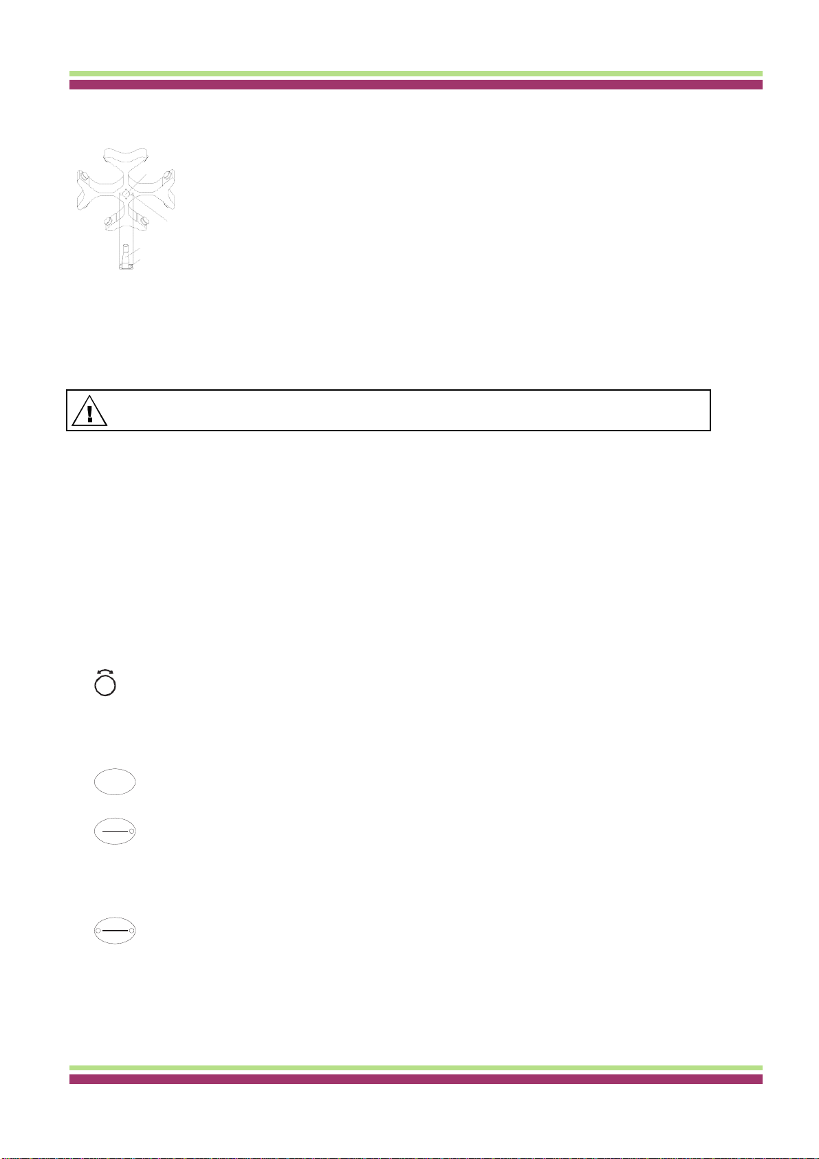
10 Installation and removal of the rotor
Clean the motor shaft (C) and the rotor drilling (A), and lightly grease the motor shaft
Aafterwards. Dirt particles between the motor shaft and the rotor hinder a perfect seating
of the rotor and cause an irregular operation.
Place the rotor vertically on the motor shaft. The motor shaft dog (D) has to fit in the
Brotor slot (B). The alignment of the groove is labelled on the rotor.
Tighten the rotor tension nut with the supplied wrench by turning in a clockwise
C
direction.
D
Check the rotor for firm seating.
Loosening the rotor: Loosen the tension nut by turning in a counter clockwise direction,
and turning until the working point for lifting. After passing the working point for lifting
the rotor is loosened from the motor shaft cone. Turn the tension nut until the rotor is
able to be lifted from the motor shaft.
11 Loading the rotor
Check the rotor for firm seating.
With swing-out rotors all rotor positions must be lined with identical hangers. Certain hangers are marked with
the number of the rotor position. These hangers may only be used in the respective rotor position. Hangers that
are marked with a set number (e.g. S001/4) may only be used in the set.
The rotors and hangers may only be loaded symmetrically. The centrifuge containers have to be
distributed evenly on all rotor positions.
12 Control and display elements
See figure on page 4.
Fig. 2: Display and control panel
Control knob
For setting the individual parameters.
Turning anticlockwise reduces the value. Turning clockwise increases the value.
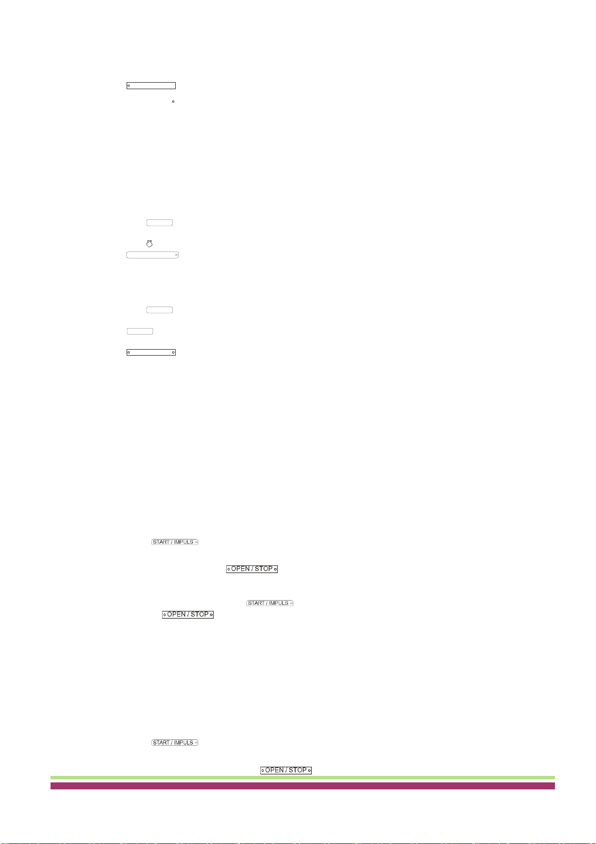
Control panel pushbuttons (keys)
Selection control key for selection of specific parameter.
The subsequent parameter is selected by every further keystroke.
- Start centrifugation run. The LED in the button lights up during the centrifugation run as long as
the rotor is turning.
- Short-term centrifugation
The centrifugation run is effected as long as the button is held down. The LED in the button
lights up during the centrifugation run as long as the rotor is turning.
- Store inputs and changes.
- End centrifugation run.
The rotor runs down with a pre-selected brake step. The right-hand LED in the button lights up until
the rotor is stationary. Once the rotor is stationary the left-hand LED flashes in the button. Pressing
the button twice triggers the EMERGENCY STOP.
- Unlock the lid.
The left-hand LED in the button goes out.
- Leave the parameter input.
11
Standard centrifuge containers of glass will not stand RCF values exceeding 4000 (DIN 58970, pg. 2).
SELECT
START
IMPULS
STOP
OPEN

THARMAC® GmbH - Cellspin® II/IIR - Instruction
manual
Switch between RPM and RCF display.
RCF values are displayed in > <.
Start pre-cooing
The pre-cooing is settable. It is pre-adjusted to 2800 RPM
Adjustment possibilities
PROG RCL Program position of the called-up program.
t/min Running time. Settable from 0 - 99 min, in 1 min increments.
t/sec Running time. Settable from 0 - 59 s, in 1 second increments.
Continuous run "". Set parameter t/min and t/sec to zero.
RPM Revolutions per minute. A numerical value from 500 RPM up to the maximum speed of the rotor can
be set. Maximum speed of the rotor.
RAD/mm Centrifugation radius. Input in mm.
The input of the radius is only possible if the RCF display (> RCF <) is selected.
RCF Relative centrifugal force. A numerical value can be set, which gives a speed between 500 RPM and the
maximum speed of the rotor. Adjustable up to 100 in intervals of 1, and from 100 in intervals of 10. The
RCF value is automatically rounded up or rounded down with regard to the RPM interval. The input of
the RCF is only possible if the RCF display (> RCF <) is selected.
Starting steps 1 - 9. Step 9 = shortest starting time, Step 1 = longest starting time.
Brake steps 0 - 9. Step 9 = shortest run-down time, Step 1 = long run-down time,
Step 0 = longest run-down time (brakeless run-down).
T °C Temperature Set Point (only in centrifuges with cooling). Adjustable from -20°C to +40°C, in 1°C intervals. The
lowest obtainable temperature depends on the rotor (see Chapter "Anhang/Appendix, Rotoren und Zubehör/Rotors
and accessories").
PROG STO Program position on which the program is stored. 9 programs can be stored (program positions 1 - 2 - 3 -
… 9). The program position # serves as temporary storage for altered adjustments.
13 Entering centrifugation parameter
Select the RPM or RCF display with the key RCF. RCF values are displayed in > <.
Select the desired parameters using the button SELECT and set using the knob .
In order to set continuous operation, the parameters t/min and t/sec must be set to zero with the
knob
. Continual running is represented in the display by the following symbol, "".
After input of all parameters, press the key START / IMPULS in order to store the adjustments on the program
position #. As confirmation,
ok
will be displayed for a short period.
12
The data on the program position # will be overwritten with every input of parameters and pressing of the
key START / IMPULS .
If no key is pressed for 8 seconds long after the selection or during the input of parameters, the previous
values will be shown in the display. The input of parameter then has to be executed again.
RCF
THARMAC® GmbH - Cellspin® II/IIR - Instruction
manual
If the permissible weight difference within the rotor loading has been exceeded, the drive shuts down during
the start-up, the unbalance display lights up, and IMBALANCE is displayed.
A centrifugation run can be stopped at any time by pushing the key .
All parameters can be selected and altered during the centrifugation run (see Chapter “Entering centrifugation
parameter”).
You can switch-over at any time between the RPM and RCF display with the key RCF. The input of the
centrifugation radius is necessary if you are working with the RCF display.
If OPEN OEFFNEN is displayed, a further operation of the centrifuge is only possible after opening the lid
once.
If R xx n-max xxxxx is displayed, then no centrifugation run has taken place as the rotor was changed
beforehand, refer to Chapter " Rotor Identification ".
14 Programming
Program input/alteration
Select the RPM or RCF display with the key RCF. RCF values are displayed in > <.
Select the desired parameters using the button SELECT and set using the knob .
In order to set continuous operation, the parameters t/min and t/sec must be set to zero with the
knob
. Continual running is represented in the display by the following symbol, "".
The parameter PROG STO can be selected using the button SELECT and the desired program position set using
the knob .
Press the button
START/ IMPULS
in order to store the setting on the desired program position.
ok
is
displayedbrieflyasconfirmation.
If the key START / IMPULS is pressed without the parameter PROG STO being activated, the settings are always
stored in the program place #.
Program recall
Select the parameter PROG RCL using the button SELECT and set the desired program position using the knob
.
Press the button START / IMPULS . The centrifugation data of the selected program position is displayed.
The parameters can be checked by pressing the button SELECT .
To leave the parameter display press the button
or press no button for a period of 8 seconds.
15 Centrifugation
Turn on the mains switch. Switch position .
Load the rotor and close the centrifuge lid.
Centrifugation with pre-set time
Adjusting time or recall a program with pre-set time (see Chapter "Programming").
Press the key START / IMPULS . The LED in the button START / IMPULS lights up for as long as the rotor turns.
After expiration of the time or with truncation of the centrifugation run by pushing the key OPEN / STOP , the run-
down is effected with the selected brake step. The brake step is displayed.
During the centrifugation run the rotational speed of the rotor or the subsequently resulting RCF value, the sample
temperature (only in centrifuges with cooling) and the remaining time will be displayed.
13
OPEN / STOP
When the centrifuge is running, according to EN / IEC 61010-2-020, no persons, dangerous substances or
objects may be within the safety margin of 300 mm around the centrifuge.
The previous data in the program position is overwritten during saving.
If no key is pressed for 8 seconds long after the selection or during the input of parameters, the previous
values will be shown in the display. The input of parameter then has to be executed again.
OPEN / STOP

THARMAC® GmbH - Cellspin® II/IIR - Instruction
manual
Continuous run
Adjustingthesymbol
orrecallacontinuousrunprogram(seeChapter"Programming").
Press the key START / IMPULS . The LED in the button START / IMPULS lights up for as long as the rotor turns. The
time metering begins at 00:00.
Press the key in order to stop the centrifugation run. The run-down is effected with the selected
brake step. The brake step is displayed.
During the centrifugation run the rotational speed of the rotor or the subsequently resulting RCF value, the sample
temperature (only in centrifuges with cooling) and the expired time will be displayed.
Short-term centrifugation
Hold down the key START / IMPULS . The LED in the button START / IMPULS lights up for as long as the rotor turns. The
time metering begins at 00:00.
Let go of the key START/ IMPULS again in order to stop the centrifugation run. The run-down is effected with the
selected brake step. The brake step is displayed.
During the centrifugation run the rotational speed of the rotor or the subsequently resulting RCF value, the sample
temperature (only in centrifuges with cooling) and the expired time will be displayed.
14
OPEN / STOP
THARMAC® GmbH - Cellspin® II/IIR - Instruction
manual
16 Emergency Stop
Press the key
twice. With Emergency Stop the run-down is effected with brake step 9 (shortest run-down time). Brake step 9 is displayed. If brake
step 0 was pre-selected, the run-down time is technically longer than with brake step 9.
17 Acoustic Signal
The acoustic signal sounds:
Upon the appearance of a disturbance in 2 second intervals.
After completion of a centrifugation run and rotor standstill in 30 second intervals.
The acoustic signal is stopped by opening the lid or pressing any key.
The signal after completion of the centrifugation run can be activated or deactivated in the following manner, if the
rotor is at standstill:
Hold down the key SELECT for 8 seconds.
After 8 seconds, SOUND / BELL appears in the display.
Set using the knob OFF or ON.
Press the key START / IMPULS in order to store the setting.
As confirmation,
ok
will be displayed for a short period.
17 Recall hours of operation
Recall hours of operation is only possible during rotor standstill.
Hold down the key SELECT for 8 seconds.
After 8 seconds, SOUND / BELL appears in the display.
Press the key SELECT once again.
The centrifuge’s hours of operation (CONTROL: ) are displayed.
Press the key
to exit the hours of operation recall
18 Cooling (only in centrifuges with cooling)
The temperature set-point can be adjusted from -20°C to +40°C. The lowest obtainable temperature is dependent on the
rotor (see Chapter "Anhang/Appendix, Rotoren und Zubehör/Rotors and accessories").
Standby-cooling
With rotor standstill and closed lid the centrifugal chamber is cooled to the pre-selected temperature. The temperature set-
point is shown in the display.
Standby cooling will be subject to a timed delay after a centrifuge run and the display will show OPEN/OEFFNEN. The
delay time can be pre-set in 1minute steps from 1 to 5 minutes. It is pre-set to 1 minute.
With the rotor standing still and the cover open the delay time can be set as follows:
Hold down the key for 8 seconds.
After 8 seconds, t/min = X appears in the display.
Use the rotary button to set the delay time.
Press the key in order to store the setting.
As confirmation, *** ok *** will be displayed for a short period.
To leave the delay time display press the key or do not press any key for a period of 8 seconds.
Pre-cooling the rotor
Press the key . The LED in the button lights up for as long as the rotor turns.
Press the button to end the pre-cooling. The run-down is effected with the selected brake step. The brake
step is displayed.
During the centrifugation run the rotational speed of the rotor or the subsequently resulting RCF value, the sample
temperature and the expired time will be displayed.
The pre-cooling speed can be adjusted in decade steps from 500 RPM to the max RPM of the rotor. It is preadjusted to
2800 RPM.
When the rotor is stationary and the lid open the pre-cooling speed can be set in the following manner:
Hold down the key for 8 seconds.
After 8 seconds, t/min = X appears in the display.
Press the key once again.
The set pre-cooling RPM - RPM = XXXX will be displayed.
Set the desired pre-cooling speed using the knob .
Press the key in order to store the setting.
As confirmation, *** ok *** will be displayed for a short period.
To leave the pre-cooling RPM display press the key or do not press any key for a period of 8 seconds.
OPEN / STOP
OPEN / STOP

THARMAC® GmbH - Cellspin® II/IIR - Instruction
manual
19 Relative centrifugal force (RCF)
The relative centrifugal force (RCF) is given as a multiple of the acceleration of gravity (g). It is a unit-free value and
serves to compare the separation and sedimentation performance.
These values are calculated using the formula below:
𝑅𝐶𝐹= (𝑅𝑃𝑀
1000)2𝑥 𝑟 𝑥 1,18 ==> 𝑅𝑃𝑀= √𝑅𝐶𝐹
𝑟 𝑥 1,118 𝑥 1000
RCF = relative centrifugal force
RPM = rotational speed (revolutions per minute)
r = centrifugal radius in mm = distance from the centre of the turning axis to the bottom of the centrifuge.
20 Centrifugation of materials or mixtures of materials with a density higher than 1.2
kg/dm3
When centrifuging with maxim revolutions per minute the density of the materials or the material mixtures may not
exceed 1.2 kg/dm3.
The speed must be reduced for materials or mixtures of materials with a higher density.
The permissible speed can be calculated using the following formula:
Reducedspeed(nred)= 1.2
Greater density [kg/dm³]
xmaximum speed[RPM]
e.g.: maximum speed RPM 4000, density 1.6 kg/dm3
nred =1.2kg/dm³ x 4000RPM=3464RPM
1.6kg/dm³
In the exceptional case that the maximum loading indicated on the hanger is exceeded, the speed must also be
reduced.
The permissible speed can be calculated using the following formula:
Reducedspeed(nred)= maximum load[g] x maximum speed[RPM]
actual load[g]
e.g.: maximum speed RPM 4000, maximum load 300 g, actual load 350 g
nred =300 g x 4000RPM=3703RPM
350 g
If in doubt you should obtain clarification from the manufacturer.
21 Rotor Identification
After every start of a centrifugation run the rotor utilised is identified.
After a change of rotor the drive switches off and the rotor code (R xx) as well as the maximum rotational speed
(n-max=xxxxx) of the rotor are displayed.
16
A further operation of the centrifuge is only possible after a single opening of the lid.
If, following a rotor change, the maximum speed of the rotor is less than the set speed, the speed is limited to
the maximum speed of the rotor.
The relative centrifugal force (RCF) stands in relation to the revolutions per minute and the centrifugal
radius.

THARMAC® GmbH - Cellspin® II/IIR - Instruction
manual
22 Emergency release
During a power failure the lid cannot be unlocked by motor. An emergency release has to be executed by hand.
See figure on page 4.
Switch off the mains switch (switch position "0").
Look through the window in the lid to be sure that the rotor has come to a standstill.
Insert the hexagonal wrench key into the bore hole (Fig. 1, A) and carefully rotate by half a turn in clockwise
direction until the lid can be opened.
Pull the hexagon socket head wrench out of the drilling again.
If the left LED in the button flashes after the centrifuge is switched on again, press the
button so that the motor-driven lid lock goes into the basic position (opened) again.
23 Maintenance and servicing
Centrifuges, rotors and accessories must not be cleaned in rinsing machines.
They may only be cleaned by hand and disinfected with liquids.
The water temperature must be between 20 –25°C.
Only detergents/disinfectants may be used which:
have a pH between 5 - 8
do not contain caustic alkalis, peroxides, chlorine compounds, acids and alkaline solutions
In order to prevent appearances of corrosion through cleaning agents or disinfectants, the application guide from
the manufacturer of the cleaning agent or disinfectant are absolutely to be heeded.
Centrifuge (housing, lid and centrifuging chamber)
Surface cleaning and care
Clean the centrifuge housing and the centrifuging chamber regularly, using soap or a mild detergent and a damp
cloth if required. For one thing, this services purposes of hygiene, and it also prevents corrosion through
adhering impurities.
Ingredients of suitable detergents:
soap, anionic tensides, non-ionic tensides.
After using detergents, remove the detergent residue by wiping with a damp cloth.
The surfaces must be dried immediately after cleaning.
In the event of condensation water formation, dry the centrifugal chamber by wiping out with an absorbent cloth.
Lightly rub the rubber seal of the centrifuge chamber with talcum powder or a rubber care product after each
cleaning.
The centrifuging chamber is to be checked for damage once a year.
Surface disinfection
If infectious materials penetrates into the centrifugal chamber this is to be disinfected immediately.
Ingredients of suitable disinfectants:
ethanol, n-propanol, isopropyl alcohol, glutardialdehyde, quaternary ammonium compounds.
After using disinfectants, remove the disinfectant residue by wiping with a damp cloth.
The surfaces must be dried immediately after disinfecting. 17
If damage is found which is relevant to safety, the centrifuge may no longer be put into operation. In this
case, notify Customer Service.
Pull the mains plug before cleaning.
Before any other cleaning or decontamination process other than that recommended by the manufacturer is
applied, the user has to check with the manufacturer that the planned process does not damage the device.
The device can be contaminated.
For emergency release disconnect the centrifuge from the mains.
Open the lid only during rotor standstill.
OPEN / STOP
OPEN / STOP
THARMAC® GmbH - Cellspin® II/IIR - Instruction
manual
Removal of radioactive contaminants
The agent must be specifically labelled as being an agent for removing radioactive contaminants.
Ingredients of suitable agents for removing radioactive contaminants:
anionic tensides, non-ionic tensides, polyhydrated ethanol.
After removing the radioactive contaminants, remove the agent residue by wiping with a damp cloth.
The surfaces must be dried directly after removing the radioactive contaminants.
Rotors and Attachments
Cleaning and care
In order to avoid corrosion and changes in materials, the rotors and accessories have to be cleaned regularly
with soap or with a mild cleaning agent and a moist cloth. Cleaning is recommended at least once a week.
Contaminants must be removed immediately.
Ingredients of suitable detergents:
soap, anionic tensides, non-ionic tensides.
After using detergents, remove detergent residue by rinsing with water (only outside of the centrifuge) or wipe off
with a damp cloth.
The rotors and accessories must be dried directly after cleaning.
Angle rotors, container and hanger made of aluminum are to be lightly greased after drying using acid-free
grease, e.g. Vaseline.
The sealing rings of bio-safety systems must be cleaned weekly.
The sealing rings are made of silicone. To guarantee the leak-tightness of the bio-safety systems, the sealing
rings must not be handled with talcum powder after cleaning or autoclaving.
Each time before using the bio-safety system, all parts of the bio-safety system must be visually inspected for
damage. In addition, the sealing ring(s) of the bio-safety system must be checked to make sure they are in the
correct installation position.
Damaged parts of the bio-safety system must be exchanged immediately.
If there are signs of crack formation, brittleness or wear, immediately replace the sealing ring in question. In the
case of lids with sealing rings which cannot be replaced, the entire lid must be exchanged.
For the available bio-safety systems, see the chapter "Appendix, Rotors and accessories".
In order to prevent corrosion as a result of moisture between the rotor and the motor shaft, the rotor should be
disassembled and cleaned at least once a month, and the motor shaft should be lightly greased.
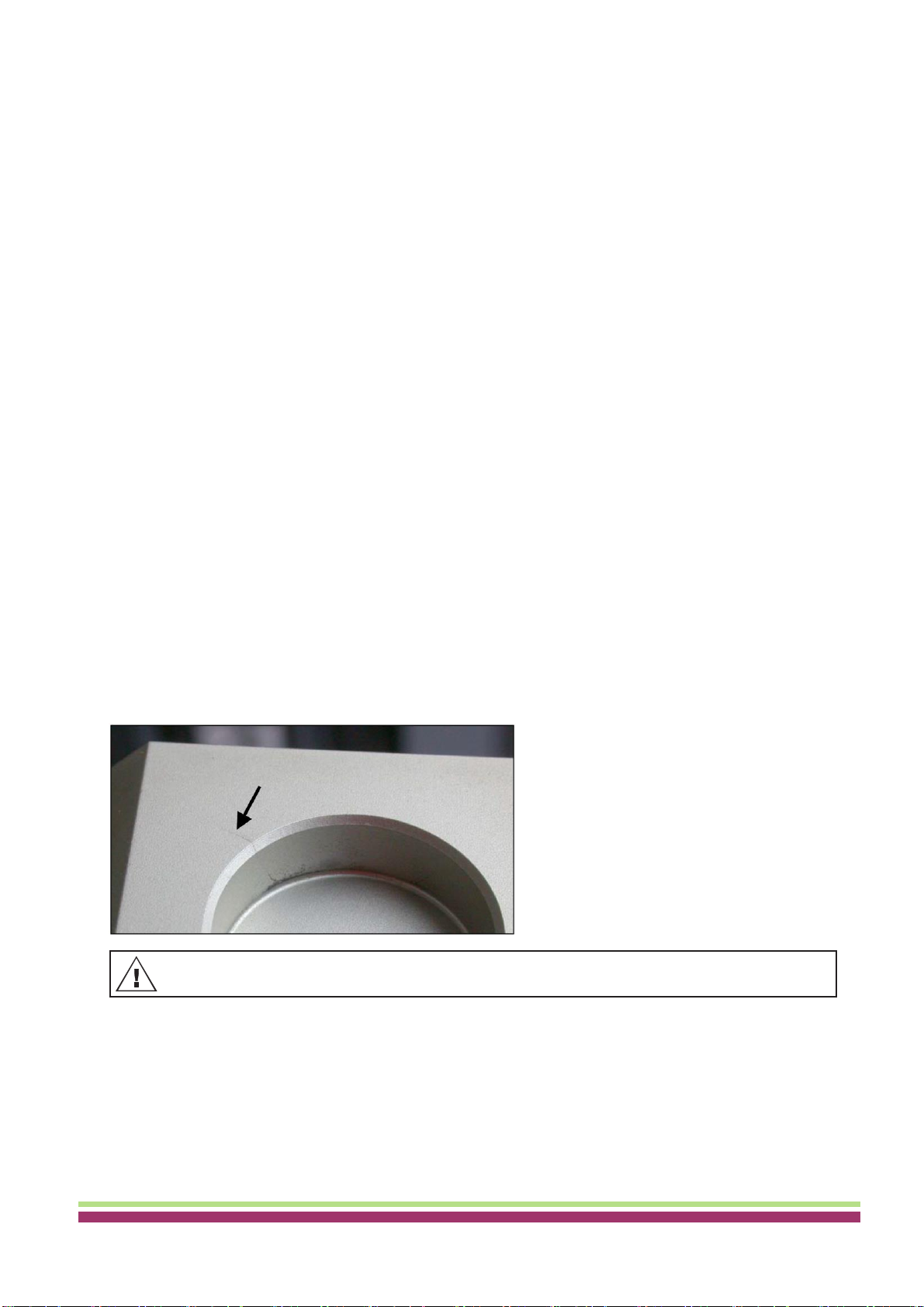
The rotors and accessories have to be checked weekly for wear and corrosion. For swing-out rotors, it is
important to check the area of the lifting lugs, for hangers, the grooves and the base should be checked for
cracks.
Example: Crack in the groove area:
Check the firm seating of the rotor on a weekly basis.
Disinfection
If infectious material should get on the rotors or accessories, they must be appropriately disinfected.
Ingredients of suitable disinfectants:
glutaraldehyde, propanol, ethyl hexanol, anionic tensides, corrosion inhibitors.
After using disinfectants, remove disinfectant residue by rinsing with water (only outside of the centrifuge) or wipe
off with a damp cloth.
The rotors and accessories must be dried directly after disinfection.
18
Rotors and attachments may no longer be utilized upon indication of wear and tear or corrosion.
THARMAC® GmbH - Cellspin® II/IIR - Instruction
manual
Removal of radioactive contaminants
The agent must be specifically labelled as being an agent for the removal of radioactive contaminants.
Ingredients of suitable agents for removing radioactive contaminants:
anionic tensides, non-ionic tensides, polyhydrated ethanol.
After removing the radioactive contaminants, remove agent residue by rinsing with water (only outside of the
centrifuge) or wipe off with a damp cloth.
The rotors and accessories must be dried directly after removing the radioactive contaminants.
Trunnions
With swing-out rotors the trunnions must be regularly lubricated in order to ensure consistent swinging out of the
hangers.
Rotors and accessories with limited service lives
The use of certain rotors, hangers and accessory parts is limited by time.
These are marked with the maximum permitted number of operating cycles or with an expiration date and the
maximum permitted number of operating cycles or just with the expiration date; e.g.:
- "einsetzbar bis Ende: V. Quartal 2011 / usable until end of: V. Quarter 2011" or
"einsetzbar bis Ende Monat/Jahr: 10/2011 / usable until end of month/year: 10/2011"
- "Max. Lauf Zyklen / max. cycles: 40000".
Autoclaving
The following accessories may be autoclaved at 121°C / 250°F (20 min):
Swing-out rotors
Angle rotors made of aluminium
Hangers made of metal
Lid with bio-seal
Adapter
23 Nothing definitive can be said about the degree of sterility.
Centrifuge containers
With leakiness or after the breakage of centrifuging containers broken container parts and leaked centrifugation
material are to be completely removed.
The rubber inserts as well as the plastic sleeves of the rotors are to be replaced after a glass breakage.
If this concerns infectious material, a disinfection process is to be executed immediately.
19
Remaining glass splitters cause further glass breakage!
The lids of the rotors and containers must be removed before autoclaving.
Autoclaving accelerates the ageing process of plastics. In addition, it can cause discolourations in plastics.
The lid of the rotors 1515 and 1515-A may only be autoclaved 10x. Afterwards, it must be exchanged for
safety reasons.
After autoclaving, the rotors and the accessories must be visually inspected for damage and any damaged
parts must be exchanged immediately.
If there are signs of crack formation, brittleness or wear, immediately replace the sealing ring in question.
In the case of lids with sealing rings which cannot be replaced, the entire lid must be exchanged.
To guarantee the leak-tightness of the bio-safety systems, the sealing rings must not be handled with
talcum powder after autoclaving.
For safety reasons, rotors, hangers and accessory parts may no longer be used if either the indicated
maximum number of operating cycles or the indicated expiration date has been reached.
This manual suits for next models
9
Table of contents
Popular Laboratory Equipment manuals by other brands


Diffinity Genomics
Diffinity Genomics RapidTip2 User handbook

Alliance Bio Expertise
Alliance Bio Expertise MEDIAWEL 10 user manual

IKA
IKA MATRIX DELTA PLUS manual

FARMALABOR
FARMALABOR TOP BLISTER Use and maintenance manual

Omni International
Omni International Bead Ruptor 4 user manual

Boekel
Boekel Rocker II operating instructions