Tharo Systems V-425E User manual

V-425E and V-434E
Users Manual
Date: 01-26-2015

CONTENTS
1
Barcode Printer
1
1.1
1.2
Box Contents
Getting to Know Your Printer
1
2
2
Printer Setup
4
2.1
2.2
2.3
2.4
2.5
Opening the Top Cover
Opening the Print Mechanism
Loading Ribbon the Host Computer
Loading Labels
4
4
5
3
Printer Setting and Control
17
3.1
3.2
3.3
Operation Panel
Label Calibration and Self-Test
Error Alerts
17
18
19
4
NetSetting for Ethernet
4.1
4.2
Installing the NetSetting Software
NetSetting Interface
20
21
5
Accessories
28
5.1
5.2
5.3
Preparation
Installing the Label Dispenser
Installing the Cutter
28
29
6
Maintenance and Adjustment
38
6.1
6.2
6.3
6.4
6.5
Cleaning the Thermal Print Head
Adjusting the Print Head Pressure
Adjusting the Print Line
Clearing Cutter jams
Troubleshooting
38
38
39
39
40
Appendix
Label Supply Hub Installation 9
7
34
41
Product Specifications
Interface Specifications
41
42
20
2.6
2.7
2.8
2.9
10
11
12
15
Preparation for Tag Printing
Connection the Printer to your Computer
EASYLABEL Start Installation
Windows Driver Installation

FCC COMPLIANCE STATEMENT
FOR AMERICAN USERS
This equipment has been tested and found to comply with the limits for a CLASS A digital device, pursuant to Part
15 of the FCC Rules. These limits are designed to provide reasonable protection against harmful interference
when the equipment is operated in a commercial environment. This equipment generates, uses, and can radiate
radio frequency energy and, if not installed and used in accordance with the instructions, may cause harmful
interference to radio communications. Operation of this equipment in a residential area is likely to cause harmful
interference in which case the user will be required to correct the interference at their own expense.
EMS AND EMI COMPLIANCE STATEMENT
FOR EUROPEAN USERS
This equipment has been tested and passed with the requirements relating to electromagnetic compatibility
based on the standards EN 55022:2006/A1:2007 Class A, EN61000-3-2:2006, EN 61000-3-3:2008 and
EN55024:1998/A1:2001/A2:2003, IEC 61000-4-2:2008 series, The equipment also tested and passed in
accordance with the European Standard EN55022 for the both Radiated and Conducted emissions limits.
V-400E SERIES
TO WHICH THIS DECLARATION RELATES
IS IN CONFORMITY WITH THE FOLLOWING STANDARDS
IEC 60950-1:2005(2nd Edition)+Am 1:2009, GB9254-2008 (Class A ) ; GB17625. 1-2003; GB4943.1-2011,
EN 55022:2006/A1:2007 Class A, EN61000-3-2:2006, EN 61000-3-3:2008 and EN55024:1998/A1:2001/A2:2003,
IEC 61000-4-2:2008 series, UL 60950-1, 1st Edition, 2007-10-31, CSA C22.2 No. 60950-1-03, 1st Edition, 2006-07,
CFR 47, Part 15
WARNING
This is a Class A product. In a domestic environment this product may cause radio interference
in which case the user may be required to correct the interference at their own expense.
㭋ḡClass AẎ⒨Ə✏䔆㴢䎖⡪ḔƏ富Ẏ⒨⏖僤怇ㇷ㗇亦䔜⹙㉗Ə✏忀䦴ガ↜Ə⏖僤曧奨䔏㈞⯠⅝⹙㉗憮⎽⇮⮅⏖堳
䙫㎑㖤˛

SAFETY INSTRUCTIONS
During the print process the Printhead will become hot. Do NOT attempt to clean the
Printhead until it has had time to cool.
The Printhead is the most fragile part of your Printer. Do NOT use sharp or hard objects to
clean the Printhead. Do NOT touch the glass surface of the Printhead with your hand.
This Printer is built exclusively to print labels, tickets and tags, continuous paper, etc. Only
use media that is recommended for a direct thermal or thermal transfer Printer.
The Printer is configured for input voltages of 110 to 240 V. Connect only to a power outlet
with a grounded contact. Always ensure the Printer is switched OFF before connecting the
power cord to an electrical outlet.
Do not expose the Printer to moisture or operate it in wet or damp areas.
The Printer will operate with the cover open if necessary. This is not recommended, as the
Printer’s moving or rotating parts can cause injury. Keep long hair, jewelry and loose
clothing away from any moving parts.
Remove the power cord from the rear of the Printer when disconnecting or attaching
accessories such as rewind units, cutters, etc.
**** There is a Danger of explosion if the battery is replaced incorrectly.
**** Dispose of used batteries according to the manufacturer’s instructions.
****Only replace the battery with an equivalent type.
Specifications are subject to change without notice.
Caution
This printer is equipped with a button cell lithium battery. This battery on the main circuit board.

1
1 Barcode Printer
1.1 Box Contents
Please check that all of the following items are included with your printer.
=V-425E / V-434E Printer
=Power Cord
=AC Adapter
=USB Cable
=Quick Start Guide
=Ribbon Hubs ( 2 )
=Empty Ribbon Core
=Label Supply Hub
=Label Guide Plates ( 2 )
=CD ( EASYLABEL Start software and Users Manual )

1 Barcode Printer
1.2 Getting To Know Your Printer
4Overview
=Front
=Rear
TOP COVER
COVER RELEASE BUTTONS
FRONT COVER
SERIAL PORT ( RS-232 )
POWER SWITCH
- ON
- OFF
FAN-FOLD LABEL SLOT
Feed slot for external label feeding
POWER JACK
USB PORT
2
OPERATION PANEL
ETHERNET PORT
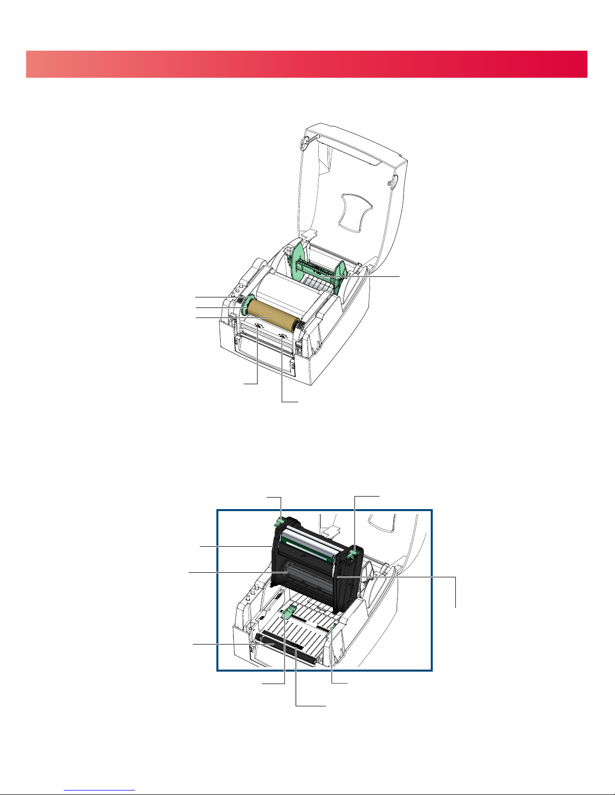
1 Barcode Printer
4Open Cover
4Open Print Mechanism
PRINTHEAD PRESSURE ADJUSTMENT SCREW ( LEFT )
PRINTHEAD PRESSURE ADJUSTMENT SCREW ( RIGHT )
LABEL SUPPLY MODULE
- LABEL SUPPLY HUB
- LABEL GUIDE PLATES ( 2 )
RIBBON MODULE
- RIBBON FEED MECHANISM
- RIBBON HUB
- EMPTY RIBBON CORE
LABEL GUIDE ( RIGHT )
RELEASE CATCH ( RIGHT )
RIBBON SUPPLY HUB
RELEASE CATCH ( LEFT )
LABEL GUIDE ( LEFT )
PRINT MECHANISM
PLATEN ROLLER
LABEL SENSOR
PRINT LINE ADJUSTMENT SCREW
3

2 Printer Setup
2.1 Opening the Top Cover
4Open the Top Cover by pressing the release buttons on both sides of the
Top Cover and lift the cover.
2.2 Open the Print Mechanism
4Open the print mechanism by pressing the Release Catches and then lift the Print Mechanism.
Press the button
COVER RELEASE BUTTONS
Press the button
Lift the printer cover
Lift the print mechanism
Press
Press
RELEASE CATCHES
4

2 Printer Setup
2.3 Loading Ribbon
4Place the new ribbon on one of the Ribbon Hubs.
Place an empty ribbon core on the other Ribbon Hub.
Attach the ribbon to the empty ribbon core and wind the ribbon around the core 2~3 times.
RIBBON SUPPLY HUB
Place on the Hub
RIBBON HUB NEW RIBBON
Place on the Hub
EMPTY RIBBON CORERIBBON HUB
RIBBON REWIND HUB
5
Wind the ribbon around the core

2 Printer Setup
4Place the Ribbon Supply Hub at the back of the Print Mechanism.
Pass the ribbon under the Print Head.
Insert the Ribbon Rewind Hub into the Print Mechanism.
Insert into the Print Mechanism
Wind up any slack
Insert into the Print Mechanism
6
Close the Print Mechanism.
Make sure that it clicks into place.
Wind up any slack in the ribbon.
This manual suits for next models
1
Table of contents


