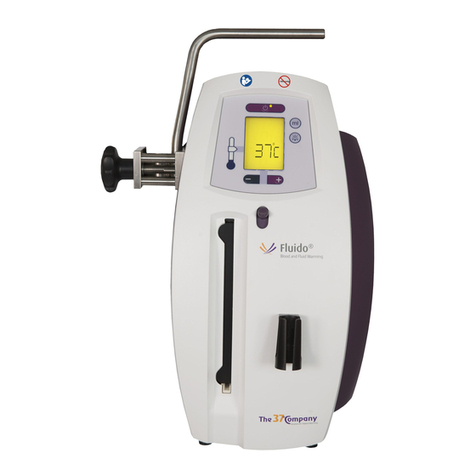
The 37Company Fluido Compact User manual

User Manual / Technical Manual
Version: INT/R683-EN-3-10-17

This page intentionally left blank!

User Manual / Technical Manual - Contents 3 of 49
Contents
1 General information.....................................................................................................................6
1.1 About this manual...................................................................................................................6
1.2 Intended use........................................................................................................................... 6
1.3 Contact....................................................................................................................................6
1.4 Warranty..................................................................................................................................7
1.5 Authorisation of personnel......................................................................................................7
1.6 Warning, caution and note..................................................................................................... 7
1.7 Disclaimer............................................................................................................................... 7
2 Safety.............................................................................................................................................8
2.1 General safety precautions.....................................................................................................8
2.1.1 Warnings......................................................................................................................... 8
2.1.2 Cautions.......................................................................................................................... 9
2.1.3 Notes...............................................................................................................................9
2.1.4 Literature......................................................................................................................... 9
2.2 Symbols................................................................................................................................ 10
3 Description..................................................................................................................................14
3.1 Overview of the device.........................................................................................................14
3.2 Overview of the control module [REF 650100].................................................................... 14
3.3 Overview of the warming module [REF 650200]................................................................. 15
3.4 Overview of the disposable sets.......................................................................................... 15
3.4.1 Standard Set [REF 672000]......................................................................................... 15
3.4.2 Standard Set with drip chamber [REF 672100]............................................................16
3.5 Overview of the control panel.............................................................................................. 16
3.6 Indicator LED behaviour....................................................................................................... 17
3.6.1 Set point indicator.........................................................................................................18
3.6.2 Repair required indicator.............................................................................................. 18
3.6.3 Overtemperature indicator............................................................................................ 19
4 Installation...................................................................................................................................20
4.1 Transport and storage.......................................................................................................... 20
4.2 Install the cables...................................................................................................................20
4.2.1 Remove the hatch........................................................................................................ 20
4.2.2 Install the interface cable..............................................................................................20
4.2.3 Install the power supply cord....................................................................................... 21
4.2.4 Place the hatch.............................................................................................................21
4.3 Change the rotation of the universal clamps (optional)........................................................21
4.4 Attach the device..................................................................................................................22
5 Operation.....................................................................................................................................23
5.1 Safety instructions before operation.....................................................................................23
5.2 Preparation before operation................................................................................................23
5.2.1 Turn the device on....................................................................................................... 24

User Manual / Technical Manual - Contents 4 of 49
5.2.2 Install the disposable set..............................................................................................24
5.2.3 Prime the standard set................................................................................................. 25
5.2.4 Prime the standard set with drip chamber................................................................... 25
5.2.5 Deaerate standard set with drip chamber.................................................................... 26
5.3 Operate the device............................................................................................................... 27
5.4 Stop the device.....................................................................................................................27
6 Maintenance................................................................................................................................30
6.1 Cleaning................................................................................................................................ 30
6.1.1 General cleaning procedure......................................................................................... 30
6.1.2 Cleaning of the warming module..................................................................................31
6.1.3 Cleaning of the control module.................................................................................... 31
6.1.4 After cleaning................................................................................................................31
7 Repair.......................................................................................................................................... 32
7.1 Hatch.....................................................................................................................................32
7.1.1 Remove hatch...............................................................................................................32
7.1.2 Place hatch................................................................................................................... 32
7.2 Cables................................................................................................................................... 33
7.2.1 Disconnect power supply cord..................................................................................... 33
7.2.2 Disconnect interface cable........................................................................................... 33
7.2.3 Connect interface cable................................................................................................33
7.2.4 Connect power supply cord..........................................................................................34
7.3 Fuse...................................................................................................................................... 34
7.3.1 Remove fuse holder..................................................................................................... 34
7.3.2 Remove fuse.................................................................................................................34
7.3.3 Place fuse..................................................................................................................... 35
7.3.4 Place fuse holder..........................................................................................................35
7.4 Warming module holder....................................................................................................... 35
7.4.1 Remove warming module holder..................................................................................35
7.4.2 Place warming module holder...................................................................................... 36
7.5 Front cover and control panel.............................................................................................. 36
7.5.1 Remove front cover and control panel......................................................................... 36
7.5.2 Place front cover and control panel............................................................................. 37
8 Test the device...........................................................................................................................40
8.1 Electrical safety test............................................................................................................. 40
8.1.1 Necessary items........................................................................................................... 40
8.1.2 Preparation....................................................................................................................40
8.1.3 Procedure......................................................................................................................40
8.2 System operation test...........................................................................................................40
8.2.1 Necessary items........................................................................................................... 40
8.2.2 Preparation....................................................................................................................41
8.2.3 Procedure......................................................................................................................41
8.3 Overtemperature alarm test..................................................................................................41
8.3.1 Necessary items........................................................................................................... 41
8.3.2 Preparation....................................................................................................................41
8.3.3 Procedure......................................................................................................................42

User Manual / Technical Manual - Contents 5 of 49
9 Specifications............................................................................................................................. 43
9.1 Specifications of the device..................................................................................................43
9.2 Specifications of the disposable sets................................................................................... 44
10 Electromagnetic compatibility................................................................................................ 46
10.1 Electromagnetic immunity...................................................................................................46
10.2 Electromagnetic emissions................................................................................................. 47
10.3 Recommended separation distances................................................................................. 47

User Manual / Technical Manual - General information 6 of 49
1 General information
1.1 About this manual
In this manual, you can find important information about how to operate the Fluido®Compact Blood
and Fluid Warming System (hereafter referred to as ‘the device’).
The device has the following modules:
• Fluido®Compact Control Module (hereafter referred to as ‘control module’)
• Fluido®Compact Warming Module (hereafter referred to as ‘warming module’)
• Two different disposable sets (referred to as 'diposable sets'):
• Fluido®Compact Standard Set (hereafter referred to as ‘standard set’)
• Fluido®Compact Standard Set with drip chamber (hereafter referred to as ‘standard set with
drip chamber’)
The manual helps you with the operation and the maintenance of the device, in a safe and
responsible manner.
Read this manual carefully. Complete all the procedures. Do the procedures in the given
sequence. Always keep the manual near the device.
1.2 Intended use
The device is developed to supply warm fluids to a patient. The Fluido Compact Standard Set is
developed for adults.
Use the device for warming:
• Crystalloid IV-fluids
• Synthetic Colloid IV-fluids
• Packed red blood cells
1.3 Contact
The 37Company
Beeldschermweg 6F
NL-3821 AH Amersfoort
The Netherlands
Tel: +31 (0)33 450 72 50
Fax: +31 (0)33 450 72 60
E-mail: [email protected]
Website: www.the37company.com

User Manual / Technical Manual - General information 7 of 49
1.4 Warranty
For the warranty provisions, refer to the website: www.the37company.com.
1.5 Authorisation of personnel
Make sure that only authorised personnel use the device.
1.6 Warning, caution and note
Warning!
A "warning" tells you that there is a risk of personal injury or death.
Caution!
A "caution" tells you that:
• there is a risk of damage to the device, and/or
• there is a risk of damage to other equipment.
A "note" gives more information.
1.7 Disclaimer
The manufacturer reserves all rights. No part of this document may be reproduced or published,
electronically, mechanically, in print, photographic print, on microfilm or by any other means
whatsoever, without the explicit consent of The 37Company.
The content of this document has been compiled with the greatest possible care and this
information can be regarded as reliable. Nevertheless, the manufacturer reserves the right to
make alterations and improvements to the device. These may not yet have been described in
the instructions. The manufacturer cannot be held liable for the final outcome of the patients’
treatment.
This document contains proprietary information that may not be disclosed to third parties. This
document may not be used without the explicit written consent of the manufacturer.
These instructions are intended for personnel authorised to work with and/or service the medical
device described in this manual.

User Manual / Technical Manual - Safety 8 of 49
2 Safety
2.1 General safety precautions
Refer to Cleaning on page 30 for specific safety precautions.
2.1.1 Warnings
• Use the device as intended. See Intended use on page 6.
• Do not place the device on a warming matrass or under a warming blanket.
Materials
• Use blood products that comply to EU and/or US standards.
• Do not mix red blood cells with drugs. See Literature on page 9: 3 and 4.
• Use saline (0.9% Sodium Chloride) to dilute red blood cells to lower the viscosity. See Literature
on page 9: 1 and 2.
• Do not mix dextrose solution (5%) with blood components. This can cause haemolysis. See
Literature on page 9: 4 and 5.
• Do not use the device for warming whole blood, platelets, cryo-precipitates or granulocyte
suspense.
Before operation
• The Fluido®Compact Warming Module is to be used only with the Fluido®Compact Control
Module and Fluido®Compact disposable sets.
• Do not use the device if the warming surface is damaged (e.g. dents, cracks). Take the device
out of service.
• Do not use the device in any of the following cases. Clean and dry the warming surface if:
• the warming surface is wet (e.g. leaked IV fluids/blood, cleaning agents).
• the warming surface is dirty (e.g. coagulated blood).
• Use a new hospital administration set for every application. (See Literature on page 9: 4).
• Use disposable sets. Use each disposable set for only one patient. Do not use a disposable set
if the expiration date has passed.
• Follow the standard IV line protocols for priming the complete infusion set and the disposable
set before connecting to a patient. Take care to ensure there is no air in the lines to cause an air
embolism.
• Do not use the device outside the environmental specification. See also Specifications on page
43.
Operation
• Do not position the warming module close to the head of the patient if inhaler therapy is used.
• If fluid leakage is observed, stop the fluid flow, and open the slider to disengage the device from
operating.
• Warming IV fluids/blood could result in outgassing. Check the disposable set every 15 minutes
on accumulated gas bubbles. These can cause air embolism.
• If the IV line runs dry, disconnect it from the patient. Re-prime the system and ensure that all air
is removed and reconnect it to the patient.

User Manual / Technical Manual - Safety 9 of 49
• The disposable set should not be used for longer than 24 hours.
• Only use a syringe at an injection point at the end of the patient line.
After operation
• The heating surface of the warming module and the cassette of the disposable set can get quite
warm when heating cold IV fluids/blood at high flow rates. Wait a few seconds after stopping the
IV fluid/blood flow before removing the cassette of the disposable set.
• After applying blood products, clean the hospital administration set using one priming volume of
saline.
• This device may be a potential biohazard during and after use. Handle and dispose in
accordance with acceptable medical practice and applicable regulations.
Other
• Modification of this equipment is not allowed.
2.1.2 Cautions
• Obey local regulations.
• Take care that the device is not dropped, to reduce the risk of damage.
• When (dis)connecting the interface cable, make sure the mains plug is disconnected from the
electrical outlet.
2.1.3 Notes
• Use the Fluido®AirGuard System if a higher flow or a larger volume is requested.
• The device is not intended to control the core temperature of the patient by itself. The device is
intended as a tool to maintain a normothermic core temperature while monitoring the patient’s
core temperature directly by a dedicated sensor inside the patient’s body.
2.1.4 Literature
1. Reserved operations Blood transfusion, Jacques, M.B., Directorate Education & Training,
2008, Leids Universitair Medisch Centrum; Reader, 2009-04-06.
2. Guidelines for the use of blood warming devices, AABB, 2002.
3. Handbook of Transfusion Medicine, DBLL McClelland, UK blood service 4th Edition, ISBN
0-11-322677-2.
4. Blood and Transplant, NHS, December 2009 version 1.
5. Fantl and Morris, Thorax (1965),20,372, Influence of dextrose on heparinized blood.

User Manual / Technical Manual - Safety 10 of 49
2.2 Symbols
Protected against falling water - Equivalent to 3-5 mm rainfall per minute for a
duration of 10 minutes. Unit is placed in its normal operating position (according to
IEC 60529).
Protected against splashing water - Water spraying at all angles at 10 litres/min at a
pressure of 80-100 kN/m2 for 5 min. (According to IEC 60529).
Pressure
Do not use the device if the package is damaged.
Caution: Federal US law restricts this device to sale by or on order of a physician.
As to electrical shock, fire and mechanical hazards only in accordance with ANSI/
AAMI ES60601-1: A1:2012, C1:2009/(R)2012 and A2:2010/(R)2012, CSA CAN/
CSA-C22.2 NO. 60601-1:14, IEC 60601-1 Edition 3.1 (2012), IEC 60601-1-6:2010
(Third Edition) + A1:2013.
Caution: risk of electrical shock.
Serial number
Catalogue / article number
Quantity
Sterilized using ethylene oxide
Batch code / lot number

User Manual / Technical Manual - Safety 11 of 49
Manufacturer
Transport and storage ambient temperature range
Transport and storage relative humidity range
Transport and storage atmospheric pressure range
Keep away from sunlight.
Keep away from rain.
AC voltage
Type BF applied parts (according to IEC 60601-1)
Expiry date, year/month
For single patient use only. Do not re-use.
Not made with natural rubber latex.
Fuse

User Manual / Technical Manual - Safety 12 of 49
Manual must be read.
Consult the instructions for use.
CE mark conform EU directive 93/42/EEC
Dispose according to European Community Directive 2002/96/EC (WEEE).
Caution. Check the instructions for use for important cautionary.
Standby/on
Upper limit temperature
Check the device and the power cords for damage. Do not use the device if it is
damaged.
Do not use a damaged disposable set to prevent damage to the device.
Do not immerse the device. Clean the appliance with standard cleaning agents.
See Cleaning on page 30.
Attach the device to a pole before you use the device.
De-aerate the disposable set before you use the device.

User Manual / Technical Manual - Safety 13 of 49
Make sure that the pressure does not exceed 300 mmHg. Do not use a (manually)
operated pressure device without a pressure indicator.
Modification update, example = MOD 6
Plug the device into an earthed mains socket.
Do not move the device on a pole during use. Remove the device from the pole
before you move it.
Class II equipment with functional earthing
Non-pyrogenic
When (dis)connecting the interface cable, make sure the mains plug is
disconnected from the electrical outlet (see Warnings on page 8).

User Manual / Technical Manual - Description 14 of 49
3 Description
3.1 Overview of the device
1. Control module (see Overview of
the control module [REF 650100]
on page 14)
2. Warming module (see Overview
of the warming module [REF
650200] on page 15)
3. Disposable set (see Overview
of the disposable sets on page
15)
3.2 Overview of the control module [REF 650100]
1. Control panel (see Overview of
the control panel on page 16)
2. Universal clamp
3. Drip chamber holder
4. Warming module holder
5. Power supply cord
6. Front cover
7. Back cover
8. Hatch

User Manual / Technical Manual - Description 15 of 49
3.3 Overview of the warming module [REF 650200]
1. Slider
2. Warming interface
3. Status indicator LED
4. Interface cable
5. Cable clamp
3.4 Overview of the disposable sets
3.4.1 Standard Set [REF 672000]
1. Luer-Lock (male)
2. Slide clamp
3. Patient line
4. Cassette with Luer-Lock (female)

User Manual / Technical Manual - Description 16 of 49
3.4.2 Standard Set with drip chamber [REF 672100]
1. Luer-Lock (male)
2. Slide clamp
3. T-connector (female) with cap
4. Patient line
5. Drip chamber
6. Cassette with Luer-Lock (female)
• Standard Set with drip chamber [672100] is not available in the U.S.
• The drip chamber on the standard set with drip chamber is meant to be used as a
deaeration chamber.
3.5 Overview of the control panel
1
2 3
4
5
1. Standby/on button
2. Standby/on indicator LED
3. Set point indicator LED
4. Repair required indicator LED
5. Overtemperature indicator LED

User Manual / Technical Manual - Description 17 of 49
3.6 Indicator LED behaviour
Control module indicator LEDs (see Overview of the control panel on page 16)
Indicator LED Behaviour Meaning
Off The device is not powered.
Orange continuous The device is in standby mode.
Standby/on
Green continuous The device is operational.
Green continuous The derived fluid temperature
at the outlet of the disposable
cassette is within range (39 ±
2°C). See Set point indicator on
page 18.
Set point
Green flashing The derived fluid temperature
at the outlet of the disposable
cassette is out of set point
range.
Repair required Yellow continuous An error is detected. The
device cannot be used. When
the system is warming an
audible alarm (repeating beep)
is also active. See Repair
required indicator on page
18.
Overtemperature Yellow continuous The safety circuit of the
device has measured a
too high temperature. See
Overtemperature indicator on
page 19.
Warming module indicator LEDs (see Overview of the warming module [REF 650200] on
page 15)
Indicator LED Behaviour Meaning
Orange continuous No disposable set is installed or
the disposable set is installed
incorrectly.
Status
Green continuous The disposable set is installed
correctly. The system is
warming.

User Manual / Technical Manual - Description 18 of 49
3.6.1 Set point indicator
The system controls the fluid outlet temperature to 39°C and does this with an accuracy of ± 2°C.
The set point indicator indicates if the derived fluid temperature at the outlet of the disposable
cassette is within range (39 ± 2°C) or not.
The maximum effective heating power is 125W. The required amount of heating power depends
on the fluid flow rate and the fluid inlet temperature. When the required heating power exceeds the
maximum effective heating power, the system is no longer able to warm the fluid to 39°C and the
outlet temperature will be lower. In addition, temperature at the end of the patient line depends on
the fluid flow rate and environmental conditions. If the fluid inlet temperature and environmental
temperature are 20°C, the temperature at the end of the patient line is 39 ± 2°C at flow rates from
5 to 100 ml/min. The following graph shows the end of patient line fluid temperatures for different
flow rates at a fluid inlet temperature of 10°C and 20°C in an environment of 20°C.
Extending the patient line can result in lower fluid temperatures at the end of the patient
line.
3.6.2 Repair required indicator
Perform the following steps when the repair required indicator LED is active (continuously yellow).
• Check if the interface cable of the warming module is correctly attached and locked to the
control module.
• Reset the device: Disconnect the power supply cord, wait a few seconds and reconnect the
power supply cord.
If the problem persists, the system needs to be replaced.

User Manual / Technical Manual - Description 19 of 49
3.6.3 Overtemperature indicator
Perform the following steps when the overtemperature indicator LED is active (continuously
yellow).
• Check the disposable cassette for air or air bubbles. If air or air bubbles are present, prime the
set again (see Prime the standard set on page 25).
• Check if the warming surface of the warming module is wet or contaminated. If wet or
contaminated, clean and dry the surface (see Cleaning on page 30).
• Reset the device: Disconnect the power supply cord, wait a few seconds and reconnect the
power supply cord.
If the problem persists, the system needs to be replaced.
In case of overtemperature, both the repair required and overtemperature LED indicators
are active (continuously yellow). When the system is warming, an audible alarm (repeating
beep) is also active.

User Manual / Technical Manual - Installation 20 of 49
4 Installation
4.1 Transport and storage
Store the device and accessories according to the transport and storage recommendations. See
Specifications on page 43.
4.2 Install the cables
4.2.1 Remove the hatch
1. Remove the bolt (A) from the hatch, using a 2 mm hex key.
The used bolt is: M3X8 A2-70 DIN7984 A.
2. Remove the hatch (B).
4.2.2 Install the interface cable
1. Turn the connector ring on the interface cable (A) to the
open position.
2. Connect the interface cable.
3. Turn the connector ring on the interface cable (B) to the
locked position.
Table of contents
Other The 37Company Medical Equipment manuals
Popular Medical Equipment manuals by other brands
Masimo
Masimo M-LNCS Series Instructions for use

St. Jude Medical
St. Jude Medical Tendril MRI LPA1200M user manual
piomic
piomic COMS One Instructions for use
Planmeca
Planmeca ProMax 3D Mid user manual
Joerns
Joerns Dolphin Fluid Immersion Simulation System User & service manual
Mediblink
Mediblink M170 Instructions for use
