The boss SRCH51101 User manual

PORTABLE INFRARED HEATER
Adequate ventilation must be provided.
WARNING: NOT FOR HOME OR RECREATIONAL VEHICLE USE.
ANSI Z83.7/CSA 2.14-2000,
ANSI Z83.7a/CSA 2.14a-2007,
ANSI Z83.7b/CSA 2.14b-2009.
4:30 CST
Model SRCH51101:Suitable for 4.5 lb gas cylinder ( included )
Model SRCH51101A: Suitable for 5 lb gas cylinder ( not included )
2
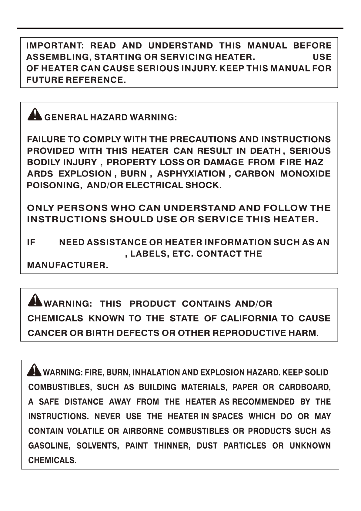
SAFETY INFORMATION
YOU
IMPROPER
GENERATES
-
INSTRUCTION MANUAL
3
SAFETY INFORMATION
The heater is designed for use as a construction heater in accordance with ANSI Z83.7/CSA 2.14-2000,
ANSI Z83.7a/CSA 2.14a-2007, ANSI Z83.7b/CSA 2.14b-2009. Other standards govern the use of
Check with your local fire safety authority if you have
questions about heater use.
Carbon Monoxide Poisoning:
Propane Gas:
to safe and proper operation of this heater.
1. The installation must conform with local codes or, in the absence of local codes, with the Stan-
square inches (774.2 cm ) of fresh, outside air before using heater.
2
area.
content.
9. Minimum heater clearances from combustibles: Sides - 3 feet (0.91 m), Top - 6 feet (1.83 m).
10. Keep cylinder(s) below 120
once.
t be replaced prior to the heater being put
and Propane
Installation Code,CSA B149.1.
or any type of unvented or enclosed
dard
49
15
14
12
4.
13
11
Some areas are affected by carbon monxide more than others. Early signs of carbon monoxide
poisoning resemble the flu, with headaches, dizziness and/or nausea. If you have these signs, TURN
THE HEATER OFF IMMEDIATELY, move to a well-ventilated area with ample fresh air, and contact
your physician immediately
for proper ventilation and have heater serviced
.
For indoor use only. When used indoors, area must be well-ventilated.
When properly used, the heater provides safe and economical
heating.

4
SAFETY INFORMATION
16. Do not use heater if altered.
17. Operate this heater only on a stable and level surface.
18. Never block air inlet (top of base) or air outlet (around top of shell) of heater.
19. Keep heater away from strong drafts, wind, water spray, rain, or dripping water.
20. Never operate this heater while sleeping. Never leave the heater unattended while in operation.
21. Keep children and animals away from heater.
22. Never move, handle or service a hot or operating heater. Severe burns may result. You must wait
15 minutes after turning heater off.
23. To prevent injury, wear gloves when handling heater.
24. Always remove cylinder from heater after each use. Always store cylinder outdoors in a well
ventilated space out of the reach of children. Never store cylinder in a building, garage, or any
other enclosed area. Never store cylinder near high heat,
exceed 120°F (49° C).
25. Turn off propane supply to heater when not in use.
26. Use only original replacement parts. This heater must use design-specific parts. Do not substitute
or use generic parts. Improper replacement parts could cause serious or fatal injuries.
27. Keep all connections and fittings clean. Make sure cylinder valve outlet is clean. Check the rubber
“O” ring on the heater inlet fuel connector for damage before each use. Replace if worn or
damaged.
28. The heater should not face directly toward any propane gas container within 20 feet (6m).
29. This appliance can only be installed in a building under construction, repair or improvement;
and can not be installed in any inhabited dwelling unit or inhabited sections of a building.
UNPACKING
1. Remove all packing items applied to heater for shipment. Keep plastic cover caps (attached to
inlet connector and hose/regulator assembly) for storage.
2. Remove all items from carton.
3. Check all items for shipping damage. If heater is damaged, promptly inform retailer where you
bought heater.

5
TABLE OF CONTENTS
2
4
6
6
8
8
9-13
14
15
16
16
6
17
18
Safety Information..................................................................................................................
Unpacking..............................................................................................................................
Ventilation................................................................................................................................
Propane Supply......................................................................................................................
Parts List.................................................................................................................................
Replacement Parts.................................................................................................................
Installation..............................................................................................................................
Safety Check...........................................................................................................................
Operation..............................................................................................................................
Storage & Maintenance.........................................................................................................
Burner Check........................................................................................................................
......................................................................................................
Troubleshooting....................................................................................................................
Warranty and Repair Service................................................................................................
7
Exploded View.................................................................................................................................
Operating Specifications

6
Operating Specifications
Fuel System: The hose/regulator assembly attaches to the propane gas supply. This provides
fuel to the heater.
Ignition System: Integrated Ignition lights the burner.
VENTILATION
WARNING:
Provide at least 120 square inches (774.2 cm2) opening of fresh,
outside air while running heater. If proper fresh, outside air ventilation is not provided,
carbon monoxide poisoning can occur. Provide proper fresh, outside air ventilation
before running heater.
PROPANE SUPPLY
Use this heater only with a propane vapor withdrawal supply system.
Fuel Information
Only
T
Position
Rating
Fuel
Consumption/Hour
0.47 lb
(0.21 kg) (0.42 kg)
10,000 Btu/Hr 20,000 Btu/Hr
HIGH
This heater is designed to operate with 4.5lb or 5lb cylinder.
The cylinder quantity relies on envionment and temperature variables. Less gas is vaporized at lower
temperatures. Your local propane gas dealer will help you select the proper supply system.
7
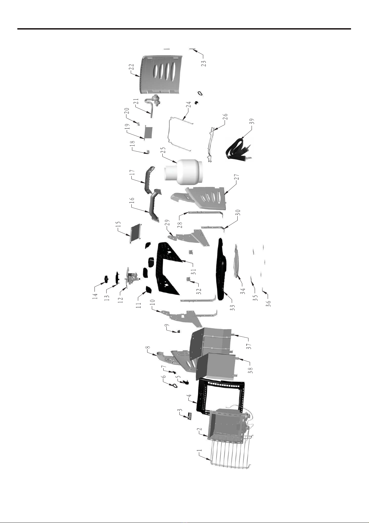
EXPLODED VIEW

8
PARTS LIST
1. Guard
2. Burner assembly
3. Badge
4. Front panel
5. Door locker
6. Hanging ring
7. Hanging ring bracket
8. Left side shield
9. Anti-tilt switch
10. Left side panel
11. Corner shield
12. Valve
13. Knob bezel
14. Knob
15. Burner assembly shield 1
16. Handle A
17. Handle B
18. Locking ring
19. Valve baffle
20. Buckle
21. Regulator and hose assembly
22. Door
23. Door axis
24. Cylinder connection bar
25. 4.5 lbs gas cylinder
26. Cylinder fixing wire
27. Right side shield
28. Support pole A
29. Right side panel
30. Support pole B
31. Top panel
32. Cylinder connection bar brac-
ket
33. Bottom panel
34. Cylinder holder
35. Washer 2
36. Washer 1
1pc
1pc
1pc
1pc
1pc
2pcs
2pcs
1pc
1pc
1pc
4pcs
1pc
1pc
1pc
1pc
1pc
1pc
1pc
1pc
1pc
1pc
1pc
2pcs
1pc
1pc
1pc
1pc
2pcs
1pc
2pcs
1pc
2pcs
1pc
1pc
2pcs
4pcs
REF.# DESCRIPTION QTY REF.# DESCRIPTION QTY
37. Burner assembly shield 3 1pc
REPLACEMENT PARTS
WARNING: Use only original
replacement parts. This heater
must use parts.
Do not substitute or use generic
parts. Improper replacement
parts could cause serious or fa-
PARTS UNDER WARRANTY
If burner will not light after repeated tries,
do not attempt to repair heater. Call Shinerich
customer service at: 1-866-814-0585.
When calling Shinerich , have ready
your name and address
how heater was malfunctioning
purchase date
model and serial numbers of your heater
38. Burner assembly shield 2 1pc
39. Sling strap 1pc
tal injuries. Using original
replacement parts will also pro-
tect your warranty coverage for -
parts replaced under warranty.

9
INSTALLATION
WARNING: Test all gas piping and connections for leaks after installation or
service. Never use an open flame to check for a leak. Apply a mixture of liquid
soap and water to all joints. If there is a leak, bubbles will form. Correct all leaks
immediately.
STEP 1
STEP 2
Press the two door buckles at the same time and then open the door (22).
5
22
Turn the door locker (5) to unlocked position“ ”as shown.
Door buckle
Unlocked
10
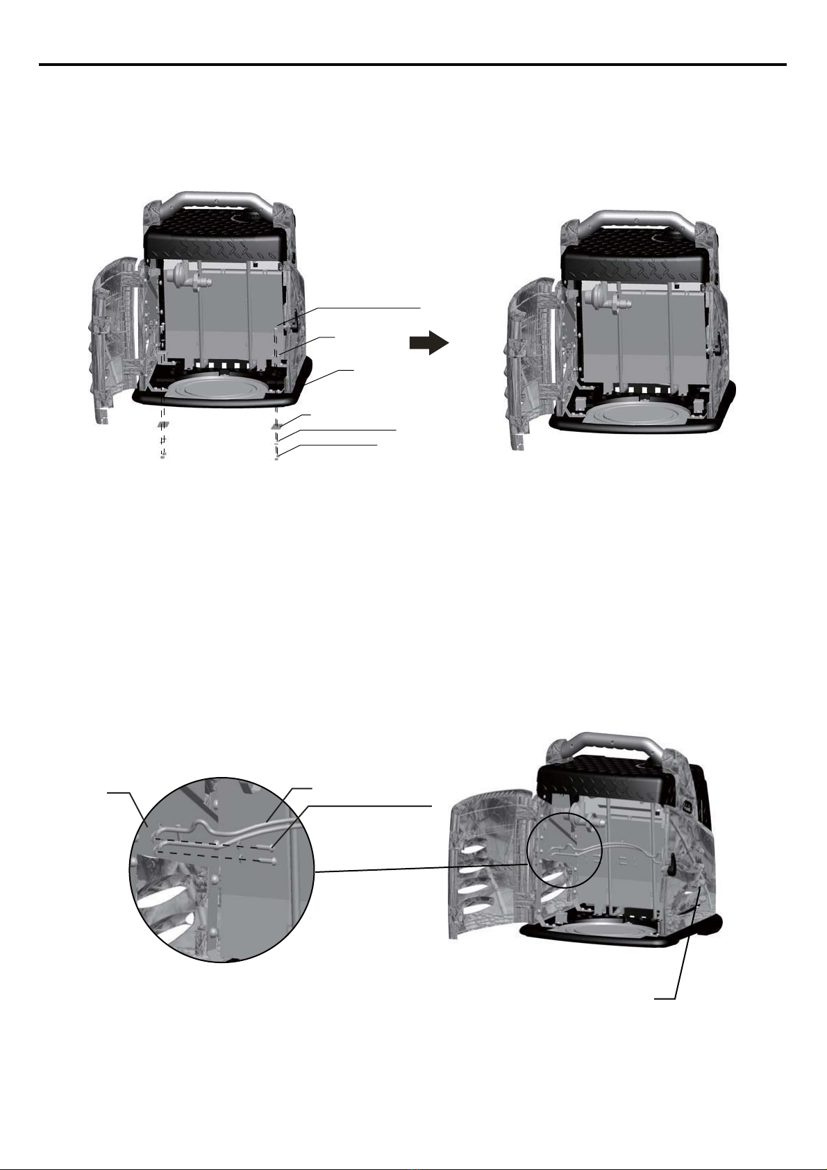
INSTALLATION
Step 3
Step 4
35
D5 washers 4pcs
M5 x 18 bolts 4pcs
M5 x 12 bolts 4pcs
M5 nuts 4pcs
32
33
29 26
10
Place 2 cylinder connection bar brackets (32) on bottom panel (33) and 2 washers (35) under bottom
panel (33) in position, then secure them with 4 M5x18 bolts, 4 D5 washers and 4 M5 nuts.
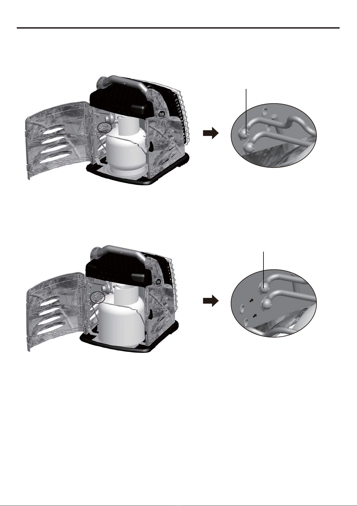
Connect the cylinder fixing wire (26) to left side panel (10) and right side panel (29) with 4 M5x12
bolts.
NOTE: When using a smaller diameter gas cylinder (such as 4.5lb gas cylinder ), install the cylinder
fixing wire to front holes. When using a bigger diameter gas cylinder (such as 5lb Worthington gas
cylinder or 5lb Manchester gas cylinder), install the cylinder fixing wire to rear holes.
Please refer to Fig.1 and Fig.2 in Page11.
11
INSTALLATION
Fig 1. (4.5lb TPA gas cylinder)
Fig 2. (5lb Worthington gas cylinder and 5lb Manchester gas cylinder)
Front holes
Rear holes

12
INSTALLATION
WARNING: Test all gas piping and connections for leaks after installation or
service. Never use an open flame to check for a leak. Apply a mixture of liquid
soap and water to all joints. If there is a leak, bubbles will form. Correct all leaks
immediately.
STEP 5
STEP 6
25
34
Warning: cylinder valve
should be facing the
same direction as the
arrow of the cylinder
holder.
Insert the guard (1) into two vertical holes at the bottom of the front panel (4) as illustrated
and then insert it into two horizontal holes at the top of the front panel.
Place gas cylinder into cylinder holder (34).
1
4
vertical hole
horizontal hole
13
INSTALLATION
WARNING: Test all gas piping and connections for leaks after installation or
service.Never use an open flame to checkforaleak.Applyamixture of liquid
soap and water to all joints. If there is a leak, bubbles will form. Correct all leaks
immediately.
STEP 7
STEP 8
21
25 24
32
24
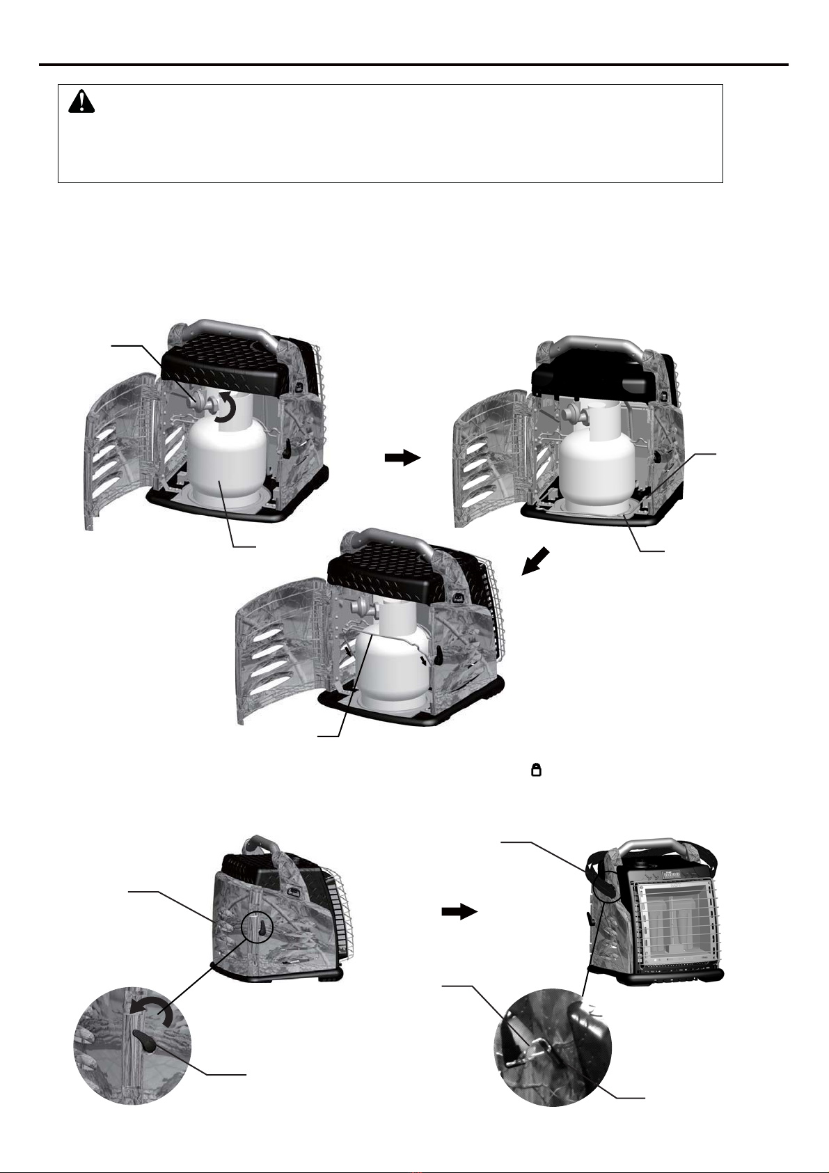
A. Connectregulatorandhoseassembly(21) to gas cylinderand turn counterclockwise to
tightenit.
B. Insert thecylinder connectionbar(24)into cylinder connectionbarbracket(32)holeand
Close the door (22) and turn door locker (5) to locked position “ ” as shown.
Attach the hooks on sling strap (39) to hanging ring (6).
then lift it up to position to secure as illustrated. Pull or press down the connection bar (24)
if needed.
5
22
Lockedposition
Sling Strap (39)
Hook
Hanging Ring (6)

14
SAFETY CHECK
CHECK FOR LEAKS
Note:
All connections on this heater have been checked for leakage at the factory. Follow these steps to
check regulator/valve/cylinder connections before operating:
1) Make leak-testing solution by mixing 1 part liquid dish soap and 3 parts water.
2) Spoon or brush several drops (or use squirt bottle) of the solution onto regulator & valve
connections, regulator & cylinder connections and illustrated connection joints.
3) Turn on gas cylinder valve. Inspect the connections and look for bubbles.
4) If no bubbles appear, the connection is safe.
5) If bubbles appear, there is leakage. Loosen and re-tighten this connection. If connection still leaks,
please call customer service: 1-866-814-0585.
1) The cylinder supply system must be arranged for vapor withdrawal;
2) The cylinder used must include a collar to protect the cylinder valve.
WARNING : ONLY AN AUTHORIZED GAS TECHNICIAN SHOULD INSTALL THIS PRODUCT.
Brush

15
OPERATION
TO START HEATER
2. Fully open the valve on the propane cylinder slowly and wait 15 seconds before step 3.
3. Push in and turn the heater control knob to the "IGN" position.
4. Once ignited, continue to hold the control knob depressed for 30 seconds,then release.
5. If heater does not light, wait 5 minutes and repeat the ignition procedure.
WARNING:
1. Review and understand the warnings in the Safety Information section (page 2).
2. To safely operate this heater, follow all local codes when using this heater.
6. When the burner remains lit, push in and turn the control knob between “HIGH”-“LOW”
to the desired heat setting.
7. If the burner goes out, push in and turn the control knob to the "OFF" position. Check fuel
supply. If fuel supply is OK, repeat the light procedure.
8. To turn off, turn control knob clockwise until it locks in “OFF” position.
TO STOP HEATER
1. Tightly close propane supply valve on cylinder by turning clockwise. Wait 15 minutes for the
heater to cool before handling heater.
3. Always detach the gas supply hose from the heater and the cylinder after each use.
TO RESTART HEATER
1. Wait five minutes after stopping heater.
2. Repeat steps of LIGHTING INSTRUCTIONS.
1. Turn the heater control knob to the "OFF" position.
2. Turn the heater control knob to the "OFF" position.
LIGHTING INSTRUCTIONS:

16
STORAGE & MAINTENANCE
CAUTION: Disconnect heater from cylinder(s) before storing.
WARNING: Never attempt to service heater while it is connected to propane
supply, operating, or hot. Severe burns can occur.
BURNER CHECK
1. Do not store heater while attached to cylinder. Remove the gas supply hose from the cylinder
by turning the fuel gas connector nut clockwise.
2. When the heater is to be stored indoors, the connection between the propane supply cylinder(s)
and the heater must be disconnected and the cylinder(s) removed from the heater and stored in
accordance with Standard for the Storage and Handling of Liquefied Petroleum Gases,
ANSI/NFPA 58 and CSA B149.1, Natural Gas and Propane Installation Code.
Always store cylinders outdoors. Never store cylinder in an enclosed area.
3. Place plastic cover caps over brass fittings on inlet connector and hose/regulator assembly.
4. Store in a dry, clean, and safe place.
1. Keep heater clean.
2. The appliance shall be kept clear and free from combustible materials,gasoline and other
flammable vapors and liquids.
3. The flow of combustion and ventilation air should not be obstructed.Use warm soapy water
for cleaning.
4. Never use flammable or corrosive cleaning agents.
5. Inspect heater before each use. Check connections for leaks. Apply mixture of liquid soap
and water to connections. Bubbles forming show a leak that must be corrected. Correct all
leaks at once.
6. Inspect hose/regulator assembly before each use. If hose is highly worn or cut, replace it
before use. The replacement hose assembly shall be that specified by the manufacturer.
7. Have heater inspected yearly by a qualified service person.
WARNING: Heater shell, top, and heated air from heater is very hot during
operation. Gradually move in closer to heater to observe flame color.
Do not touch heater shell or top. Do not get too close to heated air from
heater. Severe burns could occur.
To check for correct burner flame, look through the ventilation holes in the top of the heater to see
the burner flame.
* The flame is contained within the heater.
* The flame is essentially blue with perhaps some yellow tipping.
* There is no strong disagreeable odor, eye burning or other physical discomfort.
* There is no smoke or soot inside or outside of the heater.
* There are no unplanned or unexplained shut downs of the heater.
The parts lists and exploded view show the heater as it was constructed. Do not use a heater which
is different from that shown. In this regard, use only the hose, regulator and cylinder connection fitting
(called a POL fitting) supplied with the heater.

17
TROUBLESHOOTING
REMEDY
1. Openpropanesupplyvalve
slowly
2.
Replaceburner/valve assembly
3. Assure ignitor electrode gap
is 0.158"(4.0mm).Check
wireleadfordamage.Replace
ignitor electrode as necessary
1.
Relight, hold automaticcontrol
valve button in 45 seconds
3. Tighten connection or replace
thermocouple
4. Replaceautomaticcontrol
valve assembly
1. Checkgassupply; check
regulator output
2. Consult propane gas supplier
3. Replace burner assembly
POSSIBLE CAUSE
1. Propane supply valve closed
on cylinder(s)
2. Blockage in burner/valve
assembly
3. Ignitorelectrodenot
sparking
1. Not enough warm-up time
2. Low gas pressure
3. Thermocoupleloose or needs
to be replaced
4. Automaticcontrolvalve
needs to be replaced
1. Low gas pressure
2. Low fuel supply
3.
SYMPTOM
Burner fails to light
Burner lights but goes
out when automatic
control valve button is
released
Maximum burn rate is
low
TROUBLESHOOTING
WARNING: Never attempt to service heater while it is connected
to propane supply, operating, or hot. Severe burns can occur.
2. Check cylinder(s) for proper
gas supply
IMPORTANTMatch the color stripeonthe hang tag attached to the hose assembly with the color on
the label located near the propane inlet fitting on the heater. Do not use alternates. For this heater, the
regulator must be set as shown in"specifications (page 6)". If there is any uncertainty about the regula
-tor setting,have it checked. A heater which is not working properly must be repaired, but only by a
trained, experienced service person. In-warranty products will be repaired with no charge for
replacement parts. Please include a brief statement indicating date,place of purchase,the
nature of the problem and proof of purchase.
Out-of-warranty products will be repaired with a charge for replacement parts.

18
WARRANTY AND REPAIR SERVICE
The appliance has been manufactured under the highest standards of quality and workmanship. We
warrant to the original consumer purchaser that all aspects of this product will be free of defects in
material and workmanship for one (1) year from the date of purchase. A replacement for any defective
part will be supplied free of charge for installation by the consumer. Defects or damage caused by the
use of other than genuine parts are not covered by this warranty. This warranty shall be effective from
the date of purchase as shown in the purchaser’s receipt.
This warranty is valid for the original consumer purchaser only and excludes industrial, commercial or
business use of the product, product damage due to shipment or failure which results from alteration,
product abuse, or product misuse, whether performed by a contractor, service company, or consumer.
We will not be responsible for labor charges and/or damage incurred in installation, repair or replace-
ment, nor for incidental or consequential damage.
SHINERICH INDUSTRIAL LTD.
Toll free No.:1-866-814-0585
Addr.:8/F, Noble Center, 1006 Fuzhong 3rd. Rd.
Futian District, Shenzhen, China
This manual suits for next models
1
Table of contents
Popular Heater manuals by other brands


EQUATION
EQUATION HD15BDC Assembly, Use, Maintenance Manual

Airtecnics
Airtecnics FLY K 1000 A Installation, operation and maintenance manual

Zibro
Zibro R 421 E operating manual

Klarstein
Klarstein Hot Spot Pebble manual

Westfalia
Westfalia 96 30 53 Original instructions

Somogyi
Somogyi HOME FKA 200 instruction manual