The Worlds Models Manufacturing AeroPet 90 User manual

Warning ! This model is not a toy.
It is designed for maximum performance. Please seek advice if one is not familiar with this kind
of engine powered precision model. Operating this model without prior preparation may cause
injuries. Remember, safety is the most important thing. Always keep this instruction manual
at hand for quick reference.
* Specifications are subject to change without notice.*
INSTRUCTION MANUAL
Requires: 5-channel radio
and 1 low profile retract servo.
w/ 5 standard servos
Wing Span 67 in /1700 mm
Wing Area
Flying Weight
Fuselage Length
8 2 lbs / 3700 g.
854 sq in / 55.1 sq dm
67.5 in /1710 mm
Specifications
AeroPet 90
AeroPet 90
0.91- 1. 10 cu.in. Displacement 4-stroke
E
A
D
R
-
Y
T
-
T
S
O
O
-
F
M
L
L
Y
A
FACTORY PRE-FABRICATED
ALMOST-READY-TO-FLY (ARF) SERIES
MADE IN CHINA

INDEX
P. 3 - 11
BEFORE YOU BEGIN
PARTS LIST
ASSEMBLY
SAFETY PRECAUTIONS
P. 1
P. 2
P. 11
BEFORE YOU BEGIN
1
2
3
P. 1
AeroPet 50
AeroPet 90
3mm
Do not overlook this symbol!
Cut off shaded portion.
Peel off shaded portion
covering film.
Pay close attention here!
Pierce the shaded portion
covering film.
Must be purchased separately!
Drill holes with the specified
diameter (here: 3mm).
Ensure smooth non-binding
movement while assembling.
Apply instant glue
(C.A.glue, super glue.)
Assemble left and right
sides the same way.
Apply epoxy glue.
Apply thread locker
Warning!

P. 2
1. MAIN WING--1 pair
2. WING TUBE Ø16x479mm--1 pc.
3. SCREW PM2x22mm--4 pcs
PUSHROD Ø1.8x140mm w/ Threads(For Aileron)--2 pcs
HORN--2 sets
CLEVIS--2 pcs
STRAPER--2 pcs
FUEL TUBE Ø6x5mm--4 pcs
4. LINKAGE CONNECTOR Ø2.1mm --2 sets
5. FUSELAGE --1 set
STABILIZER & ELEVATOR--1 set
STABILIZER TUBEØ9.5x345mm--1 pc.
WASHER d3xD7mm -- 2 pcs
SCREW PA3x12mm -- 2 pcs
WIRE Ø3x180mm –1pc.
6. VERTICAL FIN & RUDDER--1 set
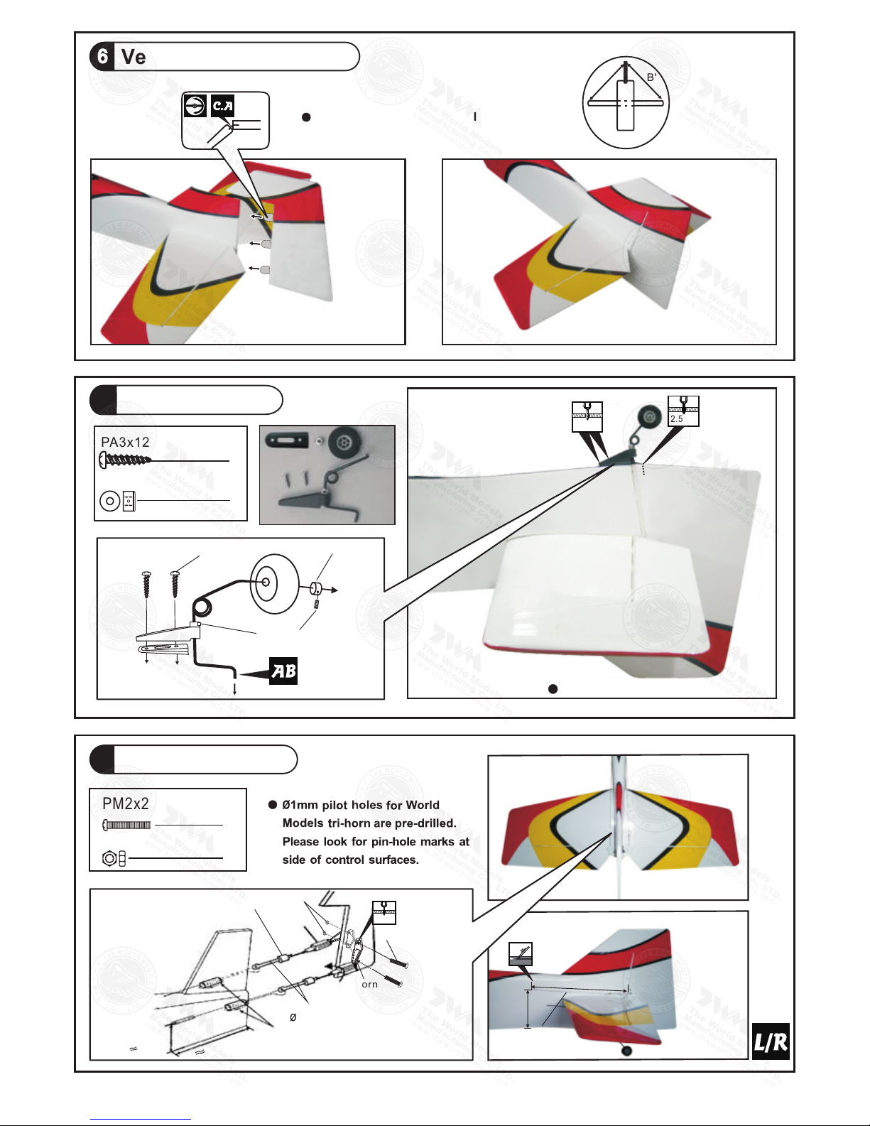
7. TAIL LANDING GEAR Ø2.5mm--1 set
SCREW PA3x12mm--2 pcs
COLLAR Ø2.6mm w/ set screw--1 set
TAIL WHEEL Ø30mm--1 pc.
8. RIGGING COUPLER Ø1.8x27mm w/ Threads(For Rudder)--2 pcs
SCREW PM2x20mm --2pcs
M2 NUT --2pcs
HORN(w/o-Balsa For Rudder)--2 pcs
FUEL TUBE Ø6X5mm--2 pcs
CLEVIS--2 pcs
WIRE Ø1x940mm(For Rudder) --2pcs
COPPER TUBE d2.5xD3.2x8mm(For Rudder)--2 pcs
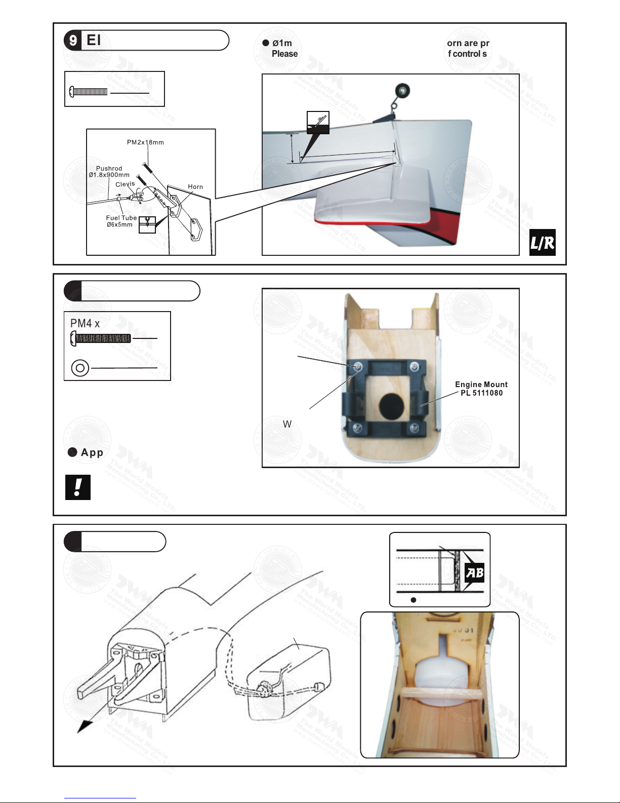
9. PUSHROD Ø1.8x900mm w/ Threads(For Elevator)--2 pcs
SCREW PM2x18mm--4 pcs
HORN--2 sets
CLEVIS--2 pcs
FUEL TUBE Ø6x5mm--2 pcs
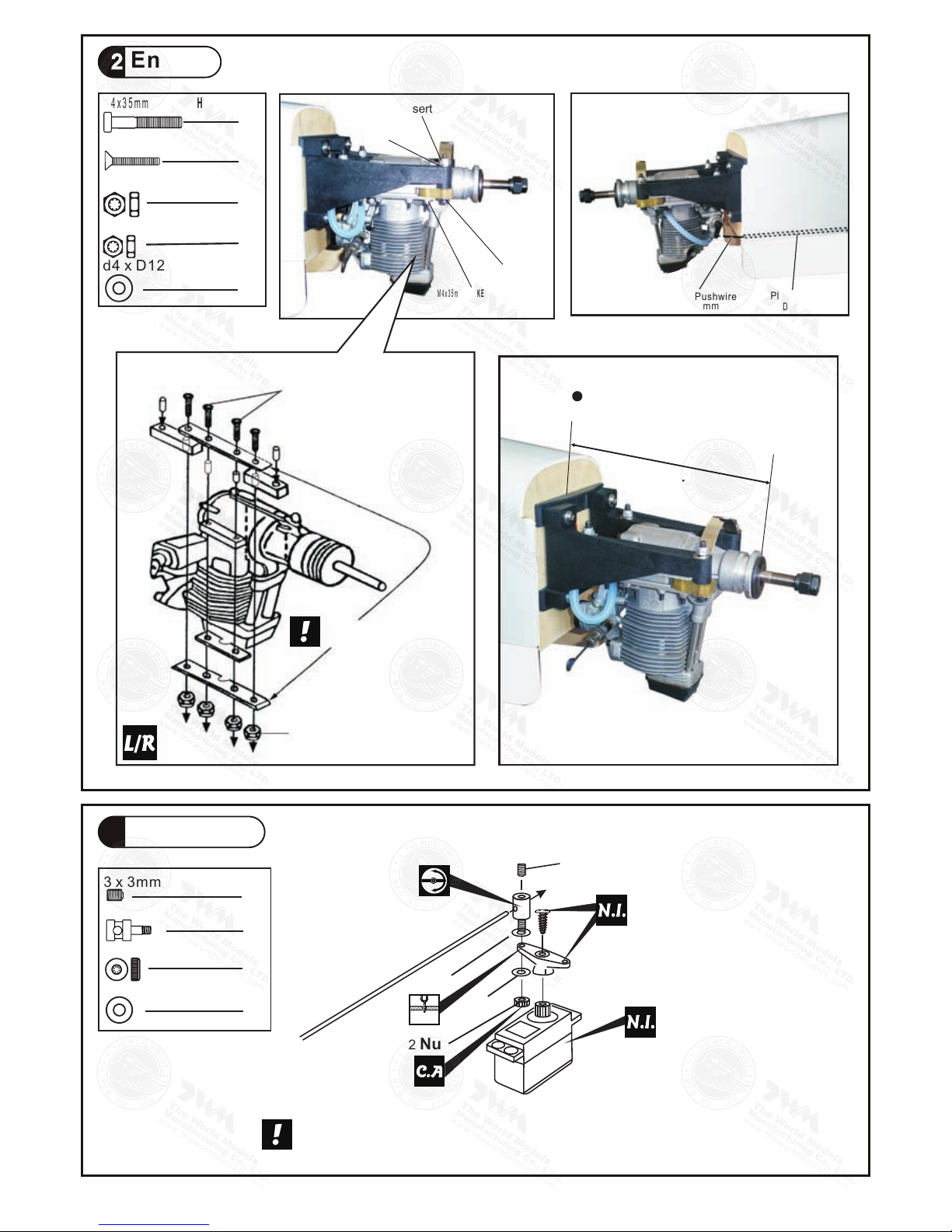
10. ENGINE MOUNT (PL5111080)--1 set
SCREW PM4x25mm--4 pcs
WASHER d4.5xD9mm--4 pcs
11. FUEL TANK 380CC--1 set
BALSA 8x8x92mm(For Fixing Fuel Tank)--1 pc.
12. THROTLE PUSHWIRE 1.2x530mm -- 1 pc.
PLASTIC TUBE d2xD3x150mm -- 1 pc.
ALUMINUM PLATE (For Engine Mount) -- 1 pc.
ANTI-VIBRATION MOUNT 4C-91 -- 1 set
INCLUDE: SOCKET HEAD SCREW M4x35mm -- 4 pcs
SCREW KM3x20mm -- 8 pcs
WASHER d4xD12mm -- 8 pcs
M3 NYLON INSERT LOCK NUT -- 8 pcs
M4 NYLON INSERT LOCK NUT -- 4 pcs
13. LINKAGE CONNECTOR Ø2.1mm--1 set
14. FUEL TUBE Ø6X5mm--1 pc.
STRAPER--1 pc.
SPONGE 60x70x90mm--1 pc.
PUSHROD CONNECTOR 8x9x20mm--1 set
PUSHROD Ø1.8x95mm(For Elevator)--1 pc.
RIGGING Z BEND Ø1.8x27mm(For Rudder)--2 pcs
COPPER TUBE d2.5xD3.2x8mm --2pcs
15. BELLY PAN--1 pc.
SCREW PM4x45mm--2 pcs
WASHER d4.2xD14.5mm--2 pcs
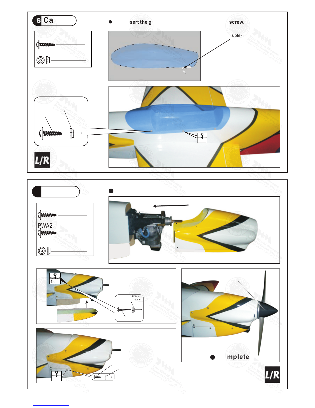
16. CANOPY--1 pc.
SCREW PWA2.3x8mm--6 pcs
SILICON GROMMET d1.5xD6.5mm--6 pcs
17. COWLING--1 pc.
UNDER COWLING-- 1pc.
TRANSPARENT DUMMY COWLING--1 pc.
SCREW PWA2.6x12mm--6 pcs
SCREW PWA2.3x8mm--6 pcs
SILICON GROMMET d1.5xD6.5mm--12 pcs
SPINNER (w.alu.back plate Ø70mm--1 set
18. DECALS:A247DEC--1 set
Ø
)
19.
COVERING:-
TOUGHLON STL 313 PINK
TOUGHLON STL 204 CREAM
TOUGHLON STL 330 CRANGE YELLW
TOUGHLON STL 201 BLACK
TOUGHLON STL 311 CUB YELLW
TOUGHLON STL 100 WHITE
Parts List

P. 3
Wing Tube
16x479mm
Ø
2Main Wing
Please apply glue to all surfaces of wing tube.
Completed
Aileron Servo Lead
1Main Wing
Apply instant type CA glue to both sides of each hinge.

P. 4
4Retractable Landing Gear Servo
Wheels down Position
To
R-side
To
L-side
Wheels up position
3 x 3mm Set Screw
Linkage Connector
M2 Nut
2mm Washer
Adjuster
4
2
2
2
3Aileron Servo
4
PM2 x22mm Screw
Bottom View
Ø1mm pi lot holes for World Models tri - horn are pre-dril l ed.
Please look for pin-hole marks at under side of control surfaces.
Straper
P M2x22mmM
Clevis
2mm
Fuel Tube
Ø6x5mm
Pushrod
Ø1.8x140mm
5Stabilizer / Elevator
AA’
A=A’
PA3 x 12mm
M3 x 6mm Set Screw
M3 x 6mm Set Screw
M3 x 6mm Set Screw
M3 x 6mm Set Screw
Bottom View
Apply instant type CA glue to both sides of each hinge.
Stabilizer Tube
Bottom View
PA3 x 12mm
≈61mm
≈150mm
d3xD7mm
Washer
Bottom View
Ø3x180mm
d3xD7mm
Washer
PA3 x 12mm Screw
d3 x D7mm Washer
2
2
2mm
2mm

P. 5
6Vertical Fin / Rudder
B = B'
B B'
Apply instant type CA glue to both
sides of each hinge.
8Rudder Pullwire
2
PM2x20mm Screw
M2 Nut
2
≈260mm
≈115mm
Rigging Coupler
1.8x27mm
Fuel Tube
Ø6x5mm
Clevis
Copper Tube
260mm
115mm
Horn
PM2x20mm
M2 NUT
2mm
Tail Landing Gear
7
1.5mm
PA3x12mm Screw
2.6mm Collar
M3x3mm Set Screw
PA3x12mm
2.6mm Collar
1
Bottom View
2
2.5mm

P. 6
9Elevator Pushrod
10 Engine Mount
11
Blind nuts are off-centered to keep
the spinner at the fuselage axis.
Ap pl y thread lock er to screws
PM4 x25mm Screw
4
d4.5x D9mm Washer
4
Fuel Tank
Fuel Tank 380cc
≈210mm
≈65mm
PM 2 x18 mm Screw
4
Ø1mm pilot holes for World Models tri-horn are pre-drilled.
Please look for pin-hole marks at under side of control surfaces.
Install Balsa 8x8x92mm
(For fixing fuel tank)
Fuel Tank
Bottom View
d4.5 x D9mm
Washer
PM 4x 25mm
2mm

P. 7
12 Engine
M4 Nylon Insert Lock Nut
4
8
4
8
d4 x D12mm Washer
KM3x20mm Screw
M3 Nylon Insert Lock Nut
8
d2xD3x150mm
Plastic tube
Throttle Pushwire
1.2x530mm
M 4 x 3 5 m m
d4 x D12mm
M4
d4 x D12mm
M 4 x 3 5 m m S O C K E T H E A D S C R E W
d4 x D12mm Washer
ANTI-VIBRATION MOUNT INSTALLATION
KM3x20mm
Make sure the rounded edges
are facing the shock absorbing
SILICON PAD.
M4 Nylon Insert Lock Nut
M 4 x 3 5 m m S O C K E T H E A D S C R E W
d4 x D12mm Washer
M3 Nylon Insert Lock Nut
Install Engine position
5.39in.
137mm
13 Servo Set
3 x 3mm Set Screw
Linkage Connector
M2 Nut
2mm Washer
1
1
1
2
Please refer to attached sheet for linkage connector installation.
Included with the radio Set.
Throttle Pushwire
3x3mm Set Screw
Throttle Servo.
2mm
2mm
Washer
M2 Nut
2mm
Washer

P. 8
14 Radio Equipment
15 Main Wing
PM4 x45mm
Washer
d4.2xD14.5mm
2
2
PM4 x45mm Screw
d4.2xD14.5mm Washer
Bottom View
Install and arrange the servo as shown in the diagram.
Fuel Tube
6x5mm
Bottom View
KM 2x8mm
M2 Nut
Elevator Push rod
Ø1.8x95mm
Copper Tube
Wire
Press down the center
1/3 portion

Cowling
17
d1.5 x D6.5 mm Silicon Grommet
12
6
PWA2.6 x12mm Screw
6
PWA2.3 x8mm Screw
P. 9
16 Canopy
d1.5 x D6.5 mm Silicon Grommet
6
6
PWA2.3 x8mm Screw
PWA2.3 x 8 mm
Silicon Grommet
d1.5xD6.5mm
1mm
Apply double-sided tape
PWA2.6 x 12mm
d1.5 x D6.5 mm
Silicon Grommet
1mm
First insert the grommet to the canopy then apply screw.
PWA2.3 x 8 mm
Silicon Grommet
d1.5xD6.5mm
First insert the grommet to the cowling then apply screw.
Spinner
Completed
1mm

AA'
Wing Setting
18
A=A'
B=B'
C=C'
BB'
C'
C
P. 1 0
Stabilizer Setting
TO INCREASE INCIDENCE ANGLE, LOOSE BOTTOM SET SCREW AND THEN TIGHTEN
TOP SET SCREW. TO REDUCE INCIDENCE ANGLE, LOOSE TOP SET SCREW AND
THEN TIGHTEN BOTTOM SET SCREW. DON'T OVER TIGHTEN SET SCREWS AS THE
INCIDENCE ANGLE ADJUSTER ARE MADE OF PLASTICS.
TOP
BOTTOM
M3X6mm Set Screw

P. 1 1
Important Safety Precautions
#First time flyer should never fly by himself / herself. Assistance from experienced flyer is
absolutely necessary.
#Pre-flight adjustment must be done before flying, it is very dangerous to fly a badly
pre-adjusted aircraft.
# is specially designed to be powered by 4c 0.91-1.
10 engine, using a
more powerful engine does not mean better performance. In fact, over powered engine
may cause severe damage and injuries.
#Make sure the air field is spacious, never fly the plane too close to people and never get
too close to a running propeller.
#If you find wrinkles on the covering as a result of weather changes, you can use hot iron
to remove the wrinkles. Please begin with lower temperature setting and gradually raise
the temperature until the wrinkles are gone. Too hot an iron may damage the covering.
#Check and re-tighten up all factory assembled screws, use thread locker if applicable.
19 Control Throws Adjust the control throws as shown in
the diagram. These throws are good for
general flying. You can adjust according
to your personal preference.
Aileron
Elevator
18mm
Rudder 40mm
20 C.G.The ideal C.G. position is 155mm(6.1 in)behind the leading edge measured at where
the wing meets the fuselage. In order to obtain the C.G. Specified, add weight to the
fuselage or move the battery position. Check the C.G. Before flying.
A247PO12680906
40mm
18mm
13mm
13mm
Measure C.G. with the wheels in retracted position
AeroPet 50
AeroPet 90
155mm
6.1
in
Warning!

Product Registration Form (US Customers)
LINKAGE CONNECTOR
HW7111050 & HW7111060
After fastening the round nut, make sure that
the linkage connector can rotate freely.
Drill 2mm hole at servo horn.
Insert linkage connector
into servo horn.
Make sure shoulder of
screw is cleared from
servo horn.
Add washer to reduce
play if necessary.
Shoulder
Tighten up the round nut
against the shoulder. Apply
CA or permanent thread
locker.

We would like to share with you any relevant information regarding your model, including
product news and free upgrade parts when applicable. Please fill in the following and send to
AirBorne Models, 4749-K, Bennett Drive, Livermore, CA 94551 USA.
1. Name:
2. Address:
3. Phone #: E-mail:
4. Model:
Wing QC# Fuselage QC#
(QC numbers are stamped on wing and fuselage)
5. Date of Purchase:
6. Store Name:
Please call AirBorne Models at 925 371 0922 for any assistance in filling this form.
Thank you very much for purchasing our product.

A247PO12680906
The World Models
Manufacturing Co., LTD.
www.thew orldmodels.com
Warbirds
Scale
Sports
Trainer
DuctedFan Pattern
Funfly
Electric
Glider
Boat
Accessories
Covering
(Lightex / Toughlon)
Table of contents
Popular Toy manuals by other brands

E-FLITE
E-FLITE Mini Ultra Stick Assembly manual

Carrera RC
Carrera RC Super Mario Flying Cape Mario Assembly and operating instructions

MS JETS
MS JETS JR FELIX manual

FUTABA
FUTABA SkyLeaf-ST instruction manual

Topmodel CZ
Topmodel CZ Butterfly instruction manual

Mattel
Mattel Disney Enchanted Cales L4106 instructions

Timbertop Toys
Timbertop Toys PRH-01 Assembly instructions

Mattel
Mattel Hot Wheels DAREDEVIL DOUBLE LOOP instructions

Geuther
Geuther Swingly Stern 2952 Instructions for assembly and use

TILLIG BAHN
TILLIG BAHN H0-Elite EW 1 quick start guide

Fisher-Price
Fisher-Price 74806 instructions

LEGO
LEGO SCOOBY-DOO 75903 Building instructions