THERACLION SONOVEIN User manual

USER MANUAL
Application (EUR)
Document THC903324-F English Version


©2022 THERACLION
All rights reserved. No part of this manual may be reproduced, stored in a retrieval system, or transmitted, in
any form or by any means, electronic, mechanical, photocopying, recording, or otherwise, without the prior
written permission of THERACLION.
SONOVEIN® is a registered trademark of THERACLION.
Confidential property of THERACLION. Information in this document may be subject to change without notice.
THERACLION
240-244 avenue Pierre Brossolette –92240 Malakoff –France
Phone +33 (0)1 55 48 90 70
Fax +33 (0)1 55 48 90 78
www.theraclion.com
2797


Sonovein User Manual –Application (EUR) THC903324-F
5
TABLE OF CONTENTS
Table Of Figures..........................................................................................................................................6
1 How to use this Manual......................................................................................................................7
1.1. Warnings and Cautions ..............................................................................................................7
2 Device Intended Use and Intended Users..........................................................................................7
2.1. Intended Use ..............................................................................................................................7
2.2. Intended Users ...........................................................................................................................7
2.3. Contraindications, Side Effects, and Recommendations ...........................................................8
2.3.1. Contraindications ...................................................................................................................8
2.3.2. Expected and Foreseeable Side Effects..................................................................................8
2.3.3. Recommendations..................................................................................................................8
3 Targeting Principles : Terms and Definitions......................................................................................9
3.1. Target, Target Segment..............................................................................................................9
3.2. Planes and Axis...........................................................................................................................9
3.3. Slice.............................................................................................................................................9
4 Treatment Procedure.........................................................................................................................9
4.1. System Installation and Preparation Steps ..............................................................................10
4.2. System Startup, EPack Installation...........................................................................................11
4.3. User Login, Patient Preparation ...............................................................................................12
4.4. VTU Positioning ........................................................................................................................15
4.5. Laser Detector Positioning .......................................................................................................16
4.6. Treatment Screen.....................................................................................................................16
4.6.1. Live View...............................................................................................................................17
4.6.2. Bottom Bar and Information Display....................................................................................18
4.6.3. Left Panel..............................................................................................................................20
4.6.4. Central Tool Panel ................................................................................................................20
4.7. Repositioning............................................................................................................................21
4.8. End of Treatment......................................................................................................................21
5 System Wrap-up and Cleaning .........................................................................................................22
5.1. EPack Removal and System Shutdown.....................................................................................22
5.2. VTU ...........................................................................................................................................24
5.3. Handprobe................................................................................................................................24
5.4. System Cleaning .......................................................................................................................25
6 Troubleshooting ...............................................................................................................................26
6.1. Error Messages.........................................................................................................................26
6.2. Customer Hotline .....................................................................................................................26

Sonovein User Manual –Application (EUR) THC903324-F
6
6.3. More Information.....................................................................................................................26
TABLE OF FIGURES
Figure 1 - Planes (indicative target example).............................................................................................9
Figure 2 - Treatment Screen Features......................................................................................................16

Sonovein User Manual –Application (EUR) THC903324-F
7
1HOW TO USE THIS MANUAL
The manuals intended to guide physicians on the use of the device for clinical treatments are delivered with each device.
•Sonovein User Manual –Commons (EUR) (THC903323)
•Sonovein User Manual –Application (EUR) (THC903324)
According to the indications you have been trained for, read entirely all the related manuals before using the system and
keep them readily available for reference.
Common Abbreviations in this Manual
HIFU
High-Intensity Focused Ultrasound
VTU
Visualization and Treatment Unit
TUS
Theraclion User Software
HEM
Hyper-Echoic Mark
1.1. WARNINGS AND CAUTIONS
This user manual contains CAUTIONS, WARNINGS and other information about what you must do to ensure the safe and proper
performance of the device. You must also follow local government rules and guidelines at all times.
Warning
> Informs the user of significant potential danger to the health of the persons involved or to the equipment.
Caution
> Indicates a possibility of device malfunction, device failure, and damages to other property or damages to the
equipment.
2DEVICE INTENDED USE AND INTENDED USERS
Warning
The device should be used only by an operator specially trained by THERACLION and in a proper clinical setting.
Warning
The product has been tested and validated only for clinical applications specified by THERACLION as indicated in this
manual.
2.1. INTENDED USE
The product is an ultrasound therapeutic medical device which is intended for the coagulation of blood vessels in patients
with superficial vein reflux.
2.2. INTENDED USERS
The device is intended to be used by professionals and requires a very thorough understanding of the following elements:
•Anatomy and physiology of the treated area,
•Ultrasound imaging,
•HIFU effects and operation.
Operators must be trained before using the device. The application training encompasses the following aspects:
•HIFU principles,
•Treatment procedure, including practical application
•Indications, contraindications and precautions for use of the device in the appropriate application.

Sonovein User Manual –Application (EUR) THC903324-F
8
2.3. CONTRAINDICATIONS, SIDE EFFECTS, AND RECOMMENDATIONS
2.3.1. Contraindications
Treatment is contra-indicated for use in patients:
•With thrombus in the vein segment to be treated,
•With complete deep vein thrombosis.
Diagnosis of reflux must be confirmed as per guidelines (the following is a non-exhaustive list of common diagnostic tools:
clinical examination, US images).
Warning
•HIFU cannot be delivered to tissues where macro calcifications induce a significant shadow in the ultrasonic
image.
•Patient must not be treated if the targeted tissues are not clearly visible on the ultrasound images.
•Patient must not be treated if the targeted tissues are too deep: the maximum depth reachable by the focal
point is 24 mm.
•The nerves and bones must be protected from HIFU exposure. Safety is ensured when the following distances to
the focal point are applied:
- When the structure is lateral to the focal point, the distance must be at least 8 mm,
- When the structure is beyond the focal point (post-focal exposure), the distance must be at least 13 mm
•The surrounding vessels must be protected from HIFU exposure. Safety is ensured when the following distances
to the focal point are applied:
- When the structure is lateral to the focal point, the distance must be at least 4 mm,
- When the structure is beyond the focal point (post-focal exposure), the distance must be at least 4,5 mm –
This information is visible on the treatment screen as the orange Deep veinous system level bar.
•The EPack balloon must not be put in contact with an ulcer.
•Make sure that the skin is free from any significantly thick scars.
2.3.2. Expected and Foreseeable Side Effects
Probable: Pain, edema (swelling), skin dysesthesia/paresthesia, subcutaneous tissue damage (induration, fibrosis),
ecchymosis/bruising (induced by local anesthesia).
Occasional: Allergy / skin irritation, skin hyper/hypo pigmentation, skin burn.
Rare: Adjacent nerve injury, infection, hematoma (if vein perforation), phlebitis, thrombus (clot) extension, pulmonary
embolism, deep venous thrombosis, analgesia/anesthesia related complications.
Any serious incident that has occurred in relation to the device should be reported to the Theraclion ([email protected])
and the competent authority of the Member State in which the user and/or patient is established.
2.3.3. Recommendations
For an optimal treatment:
•Patient treatment should be performed under appropriate pain mitigation.
•An infiltration can be performed in order to reach the indicated safety distances to sensitive structures.
•The area to be treated must be immobilized. The targeted area must remain in the same position during the
overall treatment procedure and should not be modified during the VTU movements.
•In case of significant local edema, follow the standard care procedure of your institution.
Post-procedure recommendations:
•It is highly recommended to instruct patient to ambulate frequently and refrain from strenuous activities or
heavy lifting for several days.
•Post-operative compression is recommended at physician’s discretion.

Sonovein User Manual –Application (EUR) THC903324-F
9
3TARGETING PRINCIPLES: TERMS AND DEFINITIONS
This chapter describes the device software vocabulary and figures. The operator must be familiar with these concepts before
starting treatments with the device.
3.1. TARGET, TARGET SEGMENT
The target represents the vein to be coagulated. The operator decides what the target represents exactly: it may correspond
to the full extent of the vein or to a specific region of it.
The treatment of an extended target can also be performed segment after segment. When starting a new segment, the VTU
should be carefully repositioned at the end of the previously treated segment to ensure treatment continuity.
3.2. PLANES AND AXIS
The device uses a frame of reference based on the targeted venous structure. The user software, TUS, will manage all
parameters of robotic movements.
For each target (or segment), the user needs to define the orientations to be used by the system:
•The main visualization plane will be the Transverse view,
•The main movement of the VTU will be along the defined longitudinal axis, from proximal to distal.
For an easier treatment, the longitudinal axis should be defined along the lesion’s major dimension –see VTU Positioning
section below.
Figure 1 - Planes (indicative target example)
3.3. SLICE
A slice corresponds to a transversal cut of the target. Space between slices is a characteristic of the system that cannot be
modified by user. During the procedure, the user moves the VTU slice after slice along the longitudinal axis to treat the target.
4TREATMENT PROCEDURE
Warning
Never deliver a pulse when the VTU is not in contact with the patient, and properly centered on the target.
Warning
Never deliver a pulse when the balloon is not in place and filled with the coupling liquid. Such pulse delivery would
instantly destroy the VTU power transducer.

Sonovein User Manual –Application (EUR) THC903324-F
10
Warning
The device should not be used if a part or cover is broken or removed.
Caution
Before using the device, the operator must be trained by a certified trainer. This support is necessary and can be
adapted according to the confidence level of the operator.
Caution
Before treating the operator must also read the Commons part of the User Manuals: Sonovein User Manual –
Commons (THC903323).
Caution
Before each treatment, operators must ensure they have read and understood the document Known issues and
precautions for Sonovein User Software.
4.1. SYSTEM INSTALLATION AND PREPARATION STEPS
To move the device, unlock the brakes by pressing the handle.
Caution
The handle must be in locked position when treating patients.
Install the VTU on the robotized head.
Warning
On the VTU, the imaging probe must be aligned with the HIFU transducer. When in doubt, after a shock, the VTU
must not be used and must be returned to THERACLION.
Caution
Verify the integrity of the HIFU transducer.
Caution
Be extremely careful to avoid shocks on the VTU, particularly on the transducer. Shocks can cause damages to the
VTU.
Connect the hand probe & VTU cable.

Sonovein User Manual –Application (EUR) THC903324-F
11
Connect the device to the mains supply.
Switch on the device.
The system should be installed at the right of the patient.
The front handle of the device should be aligned with the
targeted zone as shown in the picture. The blue symbol
indicates the expected location of the operator.
This device position ensures the most practical VTU
rotation angles.
4.2. SYSTEM STARTUP, EPACK INSTALLATION
Home Screen
Select Veins application, then press again to start.
System Check-up
Follow the step by step instructions displayed on the screen.
Caution
During VTU robotic check, verify that no obstacles are next to the VTU: the VTU moves in X, Y, Z
by 5 x 5 x 2 cm.

Sonovein User Manual –Application (EUR) THC903324-F
12
New EPack Installation
EPack ref. THC903400-A
Before installing the balloon, rinse the transducer and imager with the
liquid in the syringe. Discard the liquid.
Follow the step by step instructions displayed on the screen. Plug the
tubing in line with the integrated degassing system (if feature available).
Then press Installation Done.
Caution
Be extremely careful when manipulating the balloon, any scratch may lead to balloon rupture during treatment. It is
recommended to use gloves to install the balloon.
Caution
Before closing the peristaltic pumps, check that each tube is on the right path.
Caution
Ensure that nothing prevents the pumps from turning once they start.
Balloon Filling and Bubble Removal
Place the VTU as shown, with the tubes on the left-hand side.
Follow the step by step instructions displayed on the screen. Then press
Finish.
Warning
Once the EPack has been installed, a short HIFU pulse is sent to check proper functioning of the treatment head. Be
particularly cautious and verify that VTU is away from the patient and any other obstacles.
Caution
During balloon filling, ensure there is no leakage in the EPack circuit. Press the Emergency Stop button to stop the
two pumps in case of leakage.
Caution
Be careful not to damage the balloon membrane with your nails or by rubbing it onto the baffle.
Caution
Do not exert any pressure on the transducer as it may break.
Caution
Air bubbles may lead to altered image quality, reduction of the treatment efficacy, or transducer damages. The
operator must ensure that there are no bubbles left before treating.
4.3. USER LOGIN, PATIENT PREPARATION
Operator Authentication
Enter your username and password. Then press Log In.
Note: The system is ready to operate when the EPack coupling liquid has
reached the requested temperature. You can log in even if the system is
not ready to operate.

Sonovein User Manual –Application (EUR) THC903324-F
13
Patient Data Input
Enter patient data and treatment information.
Then press Go to Ultrasound Imaging.
Patient Installation
Install the patient as shown.
Place the patient’s head close to the device for full mobility of the robotic
arm.
Use cushions or holders to maintain the patient in a stable and
comfortable position.
Sonovein User Manual –Application (EUR) THC903324-F
14
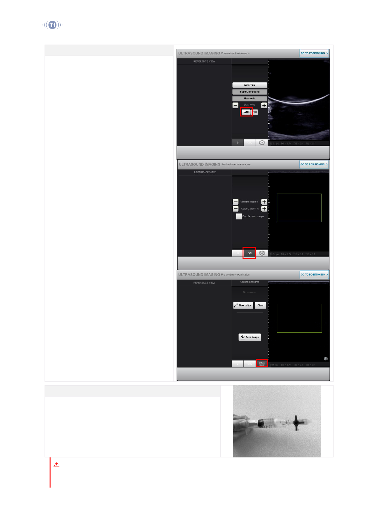
Pre-treatment Ultrasound Imaging
Press Hand to to switch to the hand probe and apply
a thin layer of gel.
Adjust the B-mode imaging parameters as needed,
with Bselected. These are: Auto TGC, Super
Compound, Harmonic and gain.
The software enables the use of Color Doppler
mode, with COL selected. Adjustments are: Steering
angle and color gain.
Verify the target dimensions and location, acquire
pre-treatment images if needed, with Freeze
selected. All saved images will be included in the
treatment report. It is recommended to mark the
path of the vein on the skin using a marker.
Infiltration (if applicable)
Any liquid injected into the treatment area must be carefully degassed to
avoid any interference with imaging and treatment quality.
Inject local anesthetic under ultrasound guidance.
When done, disconnect the hand-probe and connect the VTU, then press
Go to Positioning.
Warning
When infiltration is performed, make sure that no bubbles are present in the liquid nor syringe and needle. It is
mandatory to degas any liquid before injection.

Sonovein User Manual –Application (EUR) THC903324-F
15
Caution
The operator must ensure that one of the staff members can manage analgesia/anesthesia adverse reactions.
4.4. VTU POSITIONING
VTU Orientation Marks
Locate the imaging orientation marks on the VTU.
The vertical mark shall be placed towards the left of the practitioner.
Note that the imager is in a plane which is perfectly aligned with the blue
part of the cover.
Apply a thin layer of acoustic gel over the treatment area.
Definition of Longitudinal/Transverse Orientations
Position the VTU onto the patient’s skin, to get a transverse view.
•Adjust the position of the focal point on the target
segment, either manually or using the Command Arrows
on the live view (tap once on Display Liveview buttons to
display them).
•Adjust the treatment depth so that the target is located
between the red horizontal lines above and below.
•If necessary, press Longitudinal View button and manually
adjust the angle so that the longitudinal view is along the
target’s major dimension. Press again to rotate VTU back
to transverse view.
Remove any visible air bubble trapped in the gel and mark the VTU
position on the skin.
Press Lock to set the current VTU orientation for the treatment.
Warning
Make sure that the skin is free from any significantly thick scars.
Warning
Make sure that no objects (cloth, plaster, etc.) are in the HIFU path.
Warning
Make sure that the contact area between the balloon and the skin ensures a good ultrasound coupling. The
treatment must be stopped if shadows appear inside the HIFU path.
Warning
Make sure the skin does not touch the HIFU transducer on the VTU (through the balloon). The transducer
edge is represented in the image by a white horizontal line.

Sonovein User Manual –Application (EUR) THC903324-F
16
4.5. LASER DETECTOR POSITIONING
Laser Positioning Screen
Follow the on-screen instructions to adjust the laser position.
Check that any sudden patient movement is detected. Proper positioning
of the laser is key for the treatment safety.
Press Laser Set.
Initialize the automatic skin-tracking algorithm by adjusting the Skin Level
bar to the real-time skin level on the ultrasound live view (see also Manual
Skin section).
Warning
Make sure that the laser beam does not point to the patient eyes during the manipulation. Be particularly cautious
if the patient is asleep.
4.6. TREATMENT SCREEN
The Treatment Screen features 4 main command and information zones:
•The ultrasound live view on the right, with the pink Skin Level bar and the Command Arrows (tap once to
display them),
•The bottom bar and central information display, with the Pulse Delivery and pulse buttons, and the Power
Slider,
•The left panel, with View, B, Pressure, and Pulse tabs,
•The central tool panel, with Doppler, Longitudinal View, High Pressure, Target drawing and Manual Skin tool
buttons.
Figure 2 - Treatment Screen Features

Sonovein User Manual –Application (EUR) THC903324-F
17
4.6.1. Live View
Live Ultrasound View
The live ultrasound view displays several overlays over the real-time
image:
•The HIFU cone and focal point, in grey lines
•The transducer edge, represented by a horizontal line on top
•The pink Skin Level bar
•The orange Deep venous system safety indicator
Press Display Live View Buttons to show or hide these elements:
•The directional Command Arrows to adjust the VTU position
•The Increase/Decrease Pressure and Distal Search tool buttons
•The drawn target and sites (if the delineation tool has been
used)
Important status information messages are also displayed: Treatment
paused…, Pulse is Coming and Pulse is on.
Increase/Decrease Pressure Button
The Increase/Decrease Pressure button changes the pressure level of the EPack coupling balloon. The tool is designed to
switch between to the high-pressure and low-pressure values that the user has set under Pressure tab.
Distal Search Button
This tool is intended to help the user assess the position of the target when visibility is poor.
Press Distal Search button once to move the VTU a few slices away from the original position, to a distal location where
the target is possibly more visible. Once the target has been identified in the distal position, press Distal Search button
again to come back to the original position, while tracking the target on the image.
Warning
Never deliver a pulse when the target is not visible.
Warning
Never deliver a pulse if the vein is not properly collapsed.
Warning
Make sure that the contact area between the balloon and the skin ensures a good ultrasound coupling. The
treatment must be stopped if shadows appear inside the HIFU path.

Sonovein User Manual –Application (EUR) THC903324-F
18
Warning
Make sure the skin does not touch the HIFU transducer on the VTU (through the balloon). The transducer edge is
represented in the image by a white horizontal line.
Warning
Be careful to track the skin with precision. The energy delivered to the target depends on its depth. A mismatch
between real and monitored skin can lead to the delivery of inappropriate energy.
Warning
The operator must supervise the apparition of HEM (Hyper-Echoic marks) in the ultrasound image. If necessary, he
must adapt the HIFU power according to the update procedure described in this section.
Warning
The operator must be attentive to any visible change in the live ultrasound image, inside the target, but also outside
the target, especially inside the HIFU path.
4.6.2. Bottom Bar and Information Display
Pulse Delivery Button
The Pulse Delivery button can deliver:
•An 8-second-long pulse, when 8s button is selected
•A 4-second-long pulse, when 4s button is selected
•A 1-second-long pulse, when 1s button is selected (if feature
available)
•A 500-millisecond-long pulse, when 0.5s button is selected (if
feature available)
Each pulse is followed by a mandatory pause time for cooling.
If the Pulse button is pressed again during pause time, the next pulse will
be delivered as soon as the pause time is elapsed.
Before each pulse, check that the lesion reticule is precisely centered on
the target. Use the Doppler option to assess the local state of the vein
wall between pulses in order to fine-tune the location for energy
delivery.
Check that the vein is properly collapsed.
Power Slider
TUS suggests a default starting power.
Open the Power Slider to adjust the power: the red zone shows the
deliverable power range based on the distance from the focal point to
the Skin Level bar.
To set the power for 8-second long pulses:
•Select the 4s button and use the Power Slider to adapt the
power.
•Deliver a pulse and check for the presence of Hyper-Echoic
Marks in the live view, or using the comparison tool under
Pulse tab.
•If the HEM appears between 0-2 s during pulse emission,
decrease power by one step. If no HEM occurs, increase power
by one step. Repeat process until HEM appears between 2-4 s
during pulse emission.
•Once the proper power has been defined, select the 8s button
to perform the rest of the treatment.

Sonovein User Manual –Application (EUR) THC903324-F
19
To set the power for 1-second long pulses (if available):
•Select the 1s button and use the Power Slider to adapt the
power.
•On a given treatment site, deliver a first pulse at default power
(for the first site of each segment) or at the power defined
based on previous site.
•Check for the presence of HEM in the live view, or using the
comparison tool under Pulse tab. If no HEM is visible, increase
the power and deliver another pulse on the same site. Repeat
until HEM emergence.
When HEM emerges:
oIf the HEM exceeds the ellipse, decrease the power
by one level and move to the next treatment site.
oIf the HEM lies within the ellipse, the power level is
considered appropriate. Move to the next treatment
site.
To set the power for 500-millisecond long pulses (if available):
•Select the 0.5s button and use the Power Slider to adapt the
power.
•On a given treatment site, deliver a first pulse at default power
(for the first site of each segment) or at the power defined
based on previous site.
•Check for the presence of HEM in the live view, or using the
comparison tool under Pulse tab. If no HEM is visible, increase
the power and deliver another pulse on the same site. Repeat
until HEM emergence.
When HEM emerges:
oIf the HEM exceeds the ellipse, decrease the power
by one level and move to the next treatment site.
oIf the HEM lies within the ellipse, the power level is
considered appropriate. Move to the next treatment
site.
Caution
If the user increases the power setting by 2 steps or more, an information message will appear before pulse
delivery.
Additional Information
Depth under skin: distance from the focal point to the Skin Level bar.
Acoustic power: delivered power by the transducer to reach effective power.
Pause and Pulse duration: pause time depends on the delivered energy from the previous pulse. The progress bar
indicates elapsed time of current pulse/current pause.
Effective Power: the requested power at the focal point, estimated using a standardized value for acoustic attenuation.
HEM indicator: assesses Hyper-Echoic Mark (HEM) apparition.
Total Energy: delivered energy count for the current treatment.
Laser Detector: monitors patient movement.

Sonovein User Manual –Application (EUR) THC903324-F
20
4.6.3. Left Panel
View Tab
View tab displays a top view of the current procedure. Each slice is
indicated by a white line (green when treated). Next to any treated slice
are indicated the number of pulses and the Linear Endo-venous Energy
Density (LEED).
•Select a slice to move the VTU to the desired position (along a
longitudinal axis only).
The red lines depict the mechanical domain where the VTU can be
moved by the robot.
When changing the VTU orientation or position, the round VTU symbol
and the red mechanical limits are updated on the top view.
B/Col Tab
Btab allows setting Auto TGC, Super Compound, Harmonic and gain of the live ultrasound image. When Doppler button is
active, this tab displays settings for the color ultrasound mode such as Steering angle and color gain.
Pressure Tab
Pressure tab allows setting the high- and low-pressure levels of the EPack coupling balloon, which drive the
Increase/Decrease Pressure button of the Live View. Current balloon pressure is also indicated.
Pulse Tab
Pulse tab displays a snapshot of the live image before and after the last emitted pulse.
4.6.4. Central Tool Panel
Doppler Button
Doppler button displays an adjustable frame, in color ultrasound mode, over the live B-mode ultrasound image.
Longitudinal View Button
Longitudinal View rotates the VTU into longitudinal view. Press again to rotate VTU back to transverse view.
Target Button : Delineation Tool
Use Target button to draw, if needed, the targeted structure on the live ultrasound view. The system will automatically
show optimized positions of the focal point to treat the drawn target.
•Press Target, then carefully delineate the targeted venous structure on the live ultrasound view. Several white
ellipses (sites) will indicate the optimized positions of the focal point for the target.
•Select each site to move the focal point to the requested position.
•Press Pulse Delivery button: after a pulse has been emitted, the site is displayed in green. A site can be re-
selected.
•Press Clear button to delete the drawing.
•The position of the outline and of the sites can be adjusted using the Command Arrows on the live ultrasound
view.
This delineation tool is an alternative to the manual adjustment of the focal point using the Command Arrows.
Manual Skin Button
Table of contents
Popular Medical Equipment manuals by other brands


Getinge
Getinge Arjohuntleigh Nimbus 3 Professional Instructions for use

Mettler Electronics
Mettler Electronics Sonicator 730 Maintenance manual

Pressalit Care
Pressalit Care R1100 Mounting instruction

Denas MS
Denas MS DENAS-T operating manual

bort medical
bort medical ActiveColor quick guide

AccuVein
AccuVein AV400 user manual


