THERALASE TLC-2000 Series User manual

TLC
-
2
000
THERAPEUTIC MEDICAL LASER
Document: 600-0013
Table of Contents
1) Safety Information – Please Review Before Using the Theralase™ System .................................................................................... 1
Labeling and an Explanation.......................................................................................................................................................................................1
TLC-2000 Labels and Symbols.........................................................................................................................................................................2
Key Equipment Safety Features ..............................................................................................................................................................................3
Hardware.....................................................................................................................................................................................................................3
Operational Safety..................................................................................................................................................................................................4
Precautions.................................................................................................................................................................................................................4
Safety Warning .........................................................................................................................................................................................................5
Disclaimer Information...........................................................................................................................................................................................6
2) THERALASE™ TLC-2000 SERIES PRODUCT INFORMATION................................................................................................7
Product Overview and Technical Description................................................................................................................................................ 7
The Power Pack (TLC-2002).............................................................................................................................................................................12
The Power Supply (TLC-2003)........................................................................................................................................................................13
Laser Probes (TLC-2001) .................................................................................................................................................................................14
Accessories...............................................................................................................................................................................................................16
Contraindications in the use of Laser Therapy ................................................................................................................................................18
Cautions in the use of Laser Therapy ................................................................................................................................................................ 18
3) START-UP INFORMATION...................................................................................................................................................................21
The Power Pack (TLC-2002) ..................................................................................................................................................................................21
The Laser Probe (TLC-2001).................................................................................................................................................................................22
The Computer Tablet (TLC-2004).................................................................................................................................................................24
Set-Up Procedure........................................................................................................................................................................................................25
4) SYSTEM OPERATION OVERVIEW..................................................................................................................................................27
Steps for Advanced Treatment..............................................................................................................................................................................27
Steps for Basic Treatment........................................................................................................................................................................................28
Stop Procedure .............................................................................................................................................................................................................28
Overview of the Menu ...............................................................................................................................................................................................29
System Operation in Detail ......................................................................................................................................................................................30
Advanced Operations................................................................................................................................................................................................34
Administrator Functions ............................................................................................................................................................................................34
5) Maintenance and Service............................................................................................................................................................................. 36
Inspection and Cleaning............................................................................................................................................................................................36
Transport.........................................................................................................................................................................................................................36
Calibration/Repair of the Laser VerificationUnit............................................................................................................................................37
Service of Laser Diodes .............................................................................................................................................................................................37
Product Warranty ........................................................................................................................................................................................................37
Environmental Considerations ...............................................................................................................................................................................37
Theralase™ Customer Service Contact Information......................................................................................................................................37
6) Electro Magnetic Compatibility Information......................................................................................................................................... 38

TLC
-
2
000
THERAPEUTIC MEDICAL LASER
1
Document: 600-0013
1) SAFETY INFORMATION – Please Review Before Using the Theralase™
System
The Theralase™ TLC-2000 therapeutic laser is a Class 3B medical laser and as such is a potential hazard for direct and
indirect viewing of the laser light.
The Theralase™ TLC-2000 system is composed of four main components: The Computer Tablet,the Power Supply, the
Power Pack and the Laser Probes. The Laser Probes are the applied parts of the system. Safety and safe use of the product are
indicated both visually by the use of labels as well as equipment features. These will be detailed below.
NOTE: It is important to be well aware of all these safety details prior to using the equipment.
NOTE: In Canada, the device is to be installed and operated according to the requirements of the following
standard: CSA - Z386-14 Safe Use of Lasers in Health Care.
Caution: Federal law restricts this device to sale by or on the order of a licensed healthcare
practitioner.
Labeling and an Explanation
TLC-2001 Laser Probe
TLC-2002 Power Pack
Figure 1. Location of the safety symbols on the Theralase™ TLC-2000 System.
TLC-2003Power Supply

TLC
-
2
000
THERAPEUTIC MEDICAL LASER
2
Document: 600-0013
TLC-2000 Labels and Symbols
Canadian Standards Association Symbol (for Canada andUS):
Certifies that the product bearing this mark meets or surpasses CSA guidelines for Medical Electrical Device Standard 60601-2-22/IEC 60825-1:2007 (2nd
Edition).
ATTENTION Consult ACCOMPANYING DOCUMENTS Symbol:
Documents accompanying EQUIPMENT or an ACCESSORY and containing all important information for the USER, OPERATOR, installer or assembler of
EQUIPMENT, particularly regarding safety.
Class 3B Laser Warning Label Symbol – APERTURE LABEL:
Identifies product as a Class 3B laser, which permits human access to laser radiation in excess of the accessibleemission limits of Class 1and Class 2, but which
does not permit human access to laser radiation in excess of the accessible emission limits of Class 3B for any emission duration and wavelength.
Type BF Equipment:
Class 1ME EQUIPMENT providing a particular degree of protection against electric shock, particularly regarding allowable LEAKAGE CURRENT and
reliability of the protective earth connection. Includes an F-TYPE APPLIEDPART.
Laser Radiation Warning Label:
VISIBLE
AND
INVISIBLE
LASER
RADIATION. AVOID
EXPOSURE
TO
BEAM.
905
nm LASER:
PULSE
DURATION
200
ns; PULSE
FREQUENCY
10
kHz;
PULSE
ENERGY
0.8
µ
J; TOTAL
AVERAGE
POWER:
1000
mW;
(
5
x
200
mW) DIVERGING
ANGLE
14
o
x
23
o
660
nm LASER:
PULSE
DURATION
85
µ
s; PULSE
FREQUENCY
10
kHz;
PULSE
ENERGY
0.04
µ
J; TOTAL
AVERAGE
POWER:
400
mW;
(
4
x
100
mW) DIVERGING
ANGLE
16
o
x
22
o
IEC
60825-1:
2014
(
3
rd
Ed)
Prescription Only Symbol
Federal law restricts this device to sale by oronthe order ofa licensed healthcare practitioner.
25
˚C
0
˚C
Operation Temperature Range Symbol
This equipment shall be operated within 0° to 25° Celsius ambient temperature and maximum altitude of 2000 m.
European AuthorizedRepresentative
Obelis s.a. Corporate Office: Registered address :
Bd. Général Wahis 53 Avenue de Tervuren, 34, box 44
B-1030 Brussels, Belgium B-1040 Brussels, Belgium
Phone: 32.2.732.59.54 Fax: 32.2.732.60.03
Fragile Symbol
Do not drop.
Humidity Range Symbol
This equipment shall be operated within 0% to 80% relativehumidity.
Keep Dry Symbol
This equipment shall be operated within 0% to 80% relativehumidity.
Figure 2. Safety Labels and detailed explanations of the symbols.
C
US
EC
REP
TLC
-
2
000
THERAPEUTIC MEDICAL LASER
3
Document: 600-0013
Key Equipment Safety Features
Hardware
In addition to the safety signs placed on each of the elements of the Theralase™ system, key safety features are built into the
TLC-2000 Power Pack and Tablet software as well. These are illustrated below.
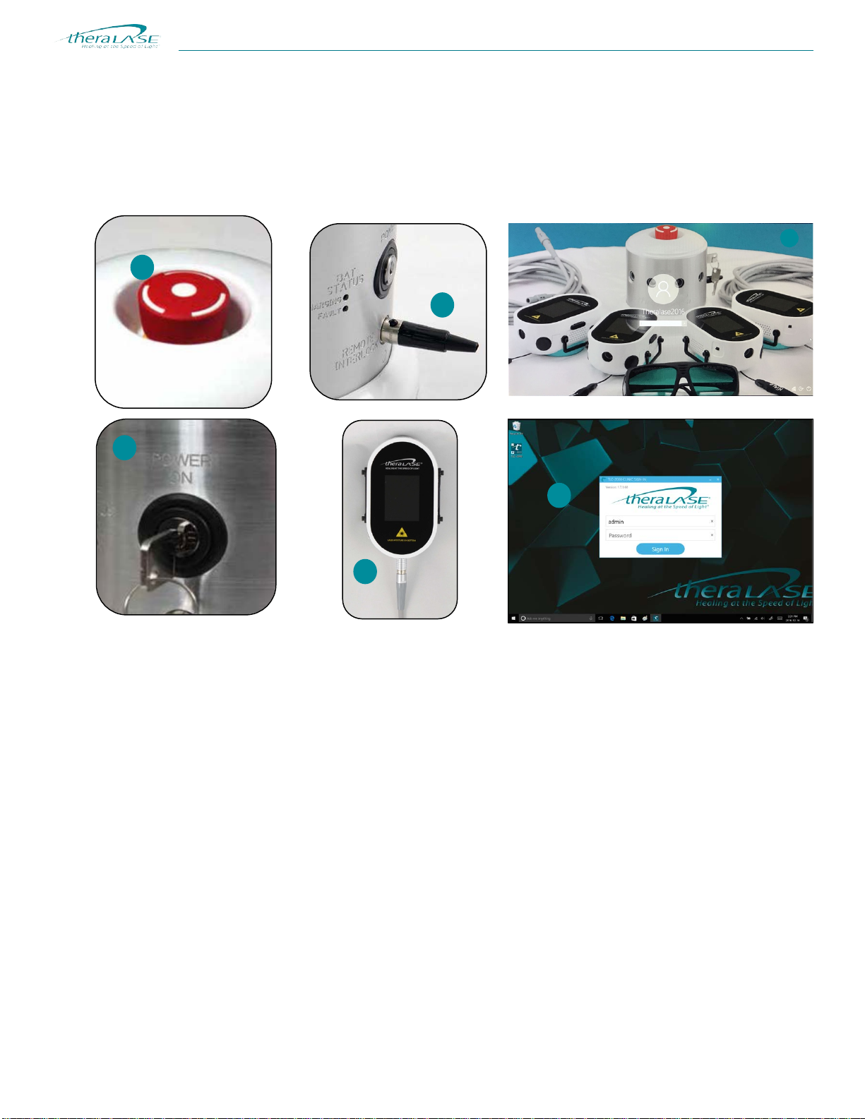
Figure 3. Safety Features.
1. Emergency Stop: This button shuts down the entire laser system immediately when pressed.
2. ON/OFF Key Switch: This is the main on / off switch for the laser system. When not in use, the keys canbe placed in
a safe location to prevent unauthorized use of the equipment.
3. Remote Interlock Connector: The Remote Interlock Connector is a connector that may be removed for
disconnecting the main power.
4. Laser Probe: The Laser Probes are the applied parts of the system. The Probe cannot operate the laserdiodes unless
a laser protocol has been received from the tablet software.
5. Tablet Software: Even if the Key Switch is left in the system with the Remote Interlock Connector in place and the
Laser Probe(s) turned on, there is yet another security feature in place. The Laser Probe(s) cannot emit laser light unless
treatment data has been received from the Theralase™ software on the tablet. To log into the operating system, the
computer tablet and the Theralase™ TLC-2000 application software requires a username and password to operate.
This now completes the 6-step security protocol system to prohibit laser use by unauthorized personnel.
1
5
3
2
4
6

TLC
-
2
000
THERAPEUTIC MEDICAL LASER
4
Document: 600-0013
Operational Safety
Caution:
Use of controls or adjustments or performance of procedures other than
those
specified
herein may result in hazardous radia
tion
exposure.
The Theralase™ TLC-2000 therapeutic laser is a Class 3B medical laser and as such is a potential hazard for direct and
indirect viewing of the laser light. As a Class 3B medical laser, the Theralase™ system carries the following warning:
Users must wear laser safety glasses with a minimum Optical Density (“OD”) of 4or greater at 905nm. Suitable eye
protection is required when using the TLC-2000 laser system. Use supplied laser safety eyewear (Part #: TLC-901) for
patient and for all practitioners involved in the laser treatment. Two sets of laser safety eyewear have been supplied with the
Theralase™ TLC-2000 laser system (1 patient and 1 practitioner pair).
Please note that Theralase™ supplies Laser Safety Eyewear with all of its products and can be ordered (Part #: TLC-901)
directly from Theralase™ Inc. The laser eyewear is for diffuse viewing of laser light only.
The Theralase™ TLC-2000 laser output is athermic. Laser diode package cases may warm up slightly duringtreatment
giving a feeling of warmth to a laser treatment. Under no circumstances should the patient experience a very hotor burning
sensation during treatment. If this occurs, discontinue the treatment immediately and contact Theralase™ Inc. for service.
The Theralase™ TLC-2000 therapeutic medical laser is a sophisticated medical device and as such should only be handled
by experienced medical practitioners suitably trained in its use.
Precautions
•Make sure that the area to be treated is free from any substance that reflects or prevents penetration of the laser
beam. It is recommended that areas to be treated by laser are cleansed, prior to treatment.
•Operate the laser in a well-illuminated area, as the pupils of the eye are smaller and not as easily damaged.
•Operate the laser in an area free from mirrors or polished metal surfaces to prevent accidentalreflections.
•Operate the laser in a segregated area with a sign posted:

TLC
-
2
000
THERAPEUTIC MEDICAL LASER
5
Document: 600-0013
WARNING: NO MODIFICATION OF THIS EQUIPMENT IS ALLOWED.
WARNING: T
O
AV
OID
RISK
OF ELECTRIC
AL
SHOCK,
THIS EQUIPMENT
MUST ONLY BE CONNECTED TO A SUPPLY MAINS WITH
PROT
ECTIV
E EARTH.
•Operate the laser probes in direct contact and perpendicular to the tissue being treated.
•Align laser probes to the area to be treated before commencing lasertreatment.
Safety Warning
•The TLC-2002 Power Pack is designed to operate with TLC-2001 Laser Probes only. A maximum of four
TLC-2001 Laser Probes may be connected to the TLC-2002 Power Pack at any one time.
•The Theralase™ TLC-2000 laser and all attachments are not designed to be protected from water intrusion and
should never be used wet or in the accompaniment of water. If the laser system becomes wet or immersed in
water, thoroughly dry the laser system and allow 48 to 72 hours in a warm environment to fully dry prior to use. If
problems persist, contact Theralase™ Inc. for service.
•The Theralase™ TLC-2000 laser and all its attachments should not be used in the presence of a flammable
anaesthetic
mixture with air or with oxygen or nitrous oxide.
•The Theralase™ TLC-2000 laser and all attachments are not suitable for use in the presence of strong
electromagnetic
field or other electrical interference.
•The Theralase™ TLC-2000 laser and all attachments are designed as an integral system and use of parts other
than the recognized accessories or parts can degrade the performance of the Theralase™ TLC-2000 laser and
may result in hazardous radiation exposure.

TLC
-
2
000
THERAPEUTIC MEDICAL LASER
6
Document: 600-0013
Disclaimer Information
The TLC-2000 therapeutic laser system is a medical device and is sold to healthcare practitioners as a tool forthe
rehabilitation of their patients. The TLC-2000 therapeutic laser system and attachments are utilized to assist in the
alleviation of their patient’s symptoms. The TLC-2000 therapeutic laser system is not promoted as a cure for any patient
ailments.
The information contained in this manual is for reference only and does not preclude the practitioner from using proper
judgement in the rehabilitation of theirpatients.
It is the practitioner’s sole responsibility to decide if laser therapy is indicated for their specific patient’s rehabilitation.
The treatment protocols detailed in this manual are for reference only and are not promoted as the only protocol available to
the practitioner.

TLC
-
2
000
THERAPEUTIC MEDICAL LASER
7
Document: 600-0013
2) THERALASE™ TLC-2000 SERIES PRODUCT INFORMATION
The TLC-2000 Therapeutic Laser System is used in the adjunctive treatment of knee pain.
The TLC-2000 laser probes are used in direct contact with tissue in order to inject photons of light (905 nm invisible laser
light and 660 nm visible red light) non-invasively and drug-free into tissue.
Product Overview and Technical Description
The Theralase™ TLC-2000 series of products is comprised of four maincomponents:
•The Computer Tablet with Theralase software (TLC-2004)
•The Power Supply (TLC-2003)
•The Laser Probe(s) (TLC-2001)
•The Power Pack (TLC-2002)
The Power Pack only supplies power to the Laser Probe(s). The Laser Probes are controlled by Theralase™ software resident
on the Tablet. Under software control, the Laser Probes operate in a patient treatment mode with the power level and time
based on the protocol resident in the tablet software. The TLC-2000 therapeutic laser system is portable and allows up to
four (4) Laser Probes to be attached to the Power Pack.
The TLC-2000 therapeutic laser system is designed to emit 905nanometer (“nm”) Near Infrared (“NIR”) invisible laser
light and 660 nm visible red light. The clinical protocol of the TLC-2000 therapeutic laser system for adjunctive treatment
of knee pain is 40 mw average power at 905 nmand 25mw average power at 660 nm.
Figure 4. TLC-2000 Therapeutic Laser System.
1
3
2
2
2
2
1
TLC-2004 Computer Tablet
2
TLC-2001 Laser Probes
3
TLC-2002 Power Pack

TLC
-
2
000
THERAPEUTIC MEDICAL LASER
Document: 600-0013
8
POWER SUPPLY (TLC-2003):
Input Voltage / Current 100 - 240 VAC / 2.2 A, 47 to 73 Hz, single phase
Output Voltage / Current +24 VDC / 4.2 A
MaximumWatts 101 W
Safety Class I
TLC-2000 OPTICAL POWER OUTPUT:
EACH NEAR INFRA-RED (NIR) LASER:
Wavelength 905 nm +/- 10 nm
Maximum AveragePower 200 mW (variable)
Repetition Rate 10.0 kHz (10,000 Hz)
Beam Divergence 12° x 20° (50% intensity)
Pulse Duration 200 nanoseconds
Total Number of NIR Lasers 5
Total NIR Laser Power 1000 mW
EACH VISIBLE LASER:
Wavelength 660 nm +/- 10nm
Beam Divergence 10° x 17° (50% intensity)
Maximum AveragePower 100 mW (variable)
Total Number of Visible Lasers 4
Total Visible Laser Power 400 mW
COMPLIANCES:
North America CAN/CSA- C22.2 NO. 60601-1:08,
CAN/CSA- C22.2 NO. 606001-2-10:14,
CAN/CSA- C22.2 NO. 606001-2-22:08,
ANSI/AAMI ES60601-1:2005 /C1:2009 (R2012) and A2 (R2012) (Corrigendum 1)
EMC/EMI IEC 60601-1-2:2007 (Ed. 3.0)
Laser Safety IEC 60825-1: 2014 (3rd Ed)
Global Quality Management ISO-13485
EQUIPMENT CLASSIFICATIONS:
Laser Class Class 3B medical laser
Risk Class 2G medical equipment
Electrical Shock Protection BF Class 1 ME
Water Protection IPX0(notwater-tight)
EMC Class A (commercial use)
PHYSICAL CHARACTERISTICS:
Power Pack Dimensions 140 mm x 140 mm
Probe Dimensions 75 mm x 135 mm x 40 mm
Weight 430 g
AMBIENT CONDITIONS:
Storage &Transport 0o - 40o C
Operation
Maximum Ambient Temperature 25o C
Maximum Operating Altitude 2000 m
TLC
-
2
000
THERAPEUTIC MEDICAL LASER
Document: 600-0013
9
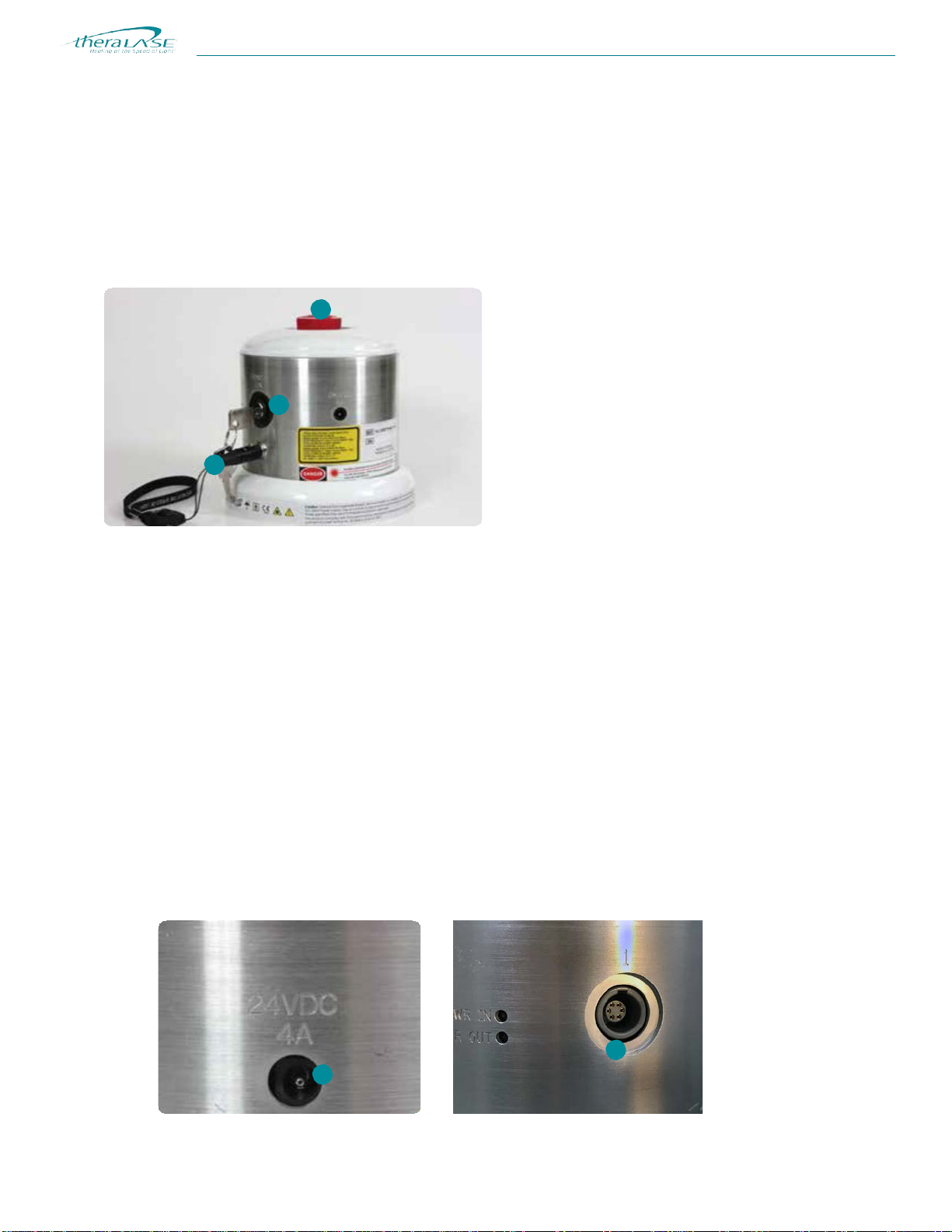
Laser Probe Port
Unit ON Indicator
Laser Probe Power ON Indicator
Remote Interlock Connector
Emergency (E-STOP) Switch
Key Switch
WARNING:
PLEASE DISCONNECT POWER SUPPLY BEFORE SERVICING.
The Power Pack (TLC-2002)
The Theralase™ TLC-2000 laser system Power Pack (TLC-2002) is shown below. The Power Pack consists of an
aluminum case, a plastic top and bottom, and a separate plastic stand that the bottom of the Power Pack fits into. There are
four ports to accommodate up to four TLC-2001 LaserProbes.
Thetop of the unit has an emergency STOP button (red button with white arrows). The front of the unit has a key switch for
switching the unit off
and prohibiting
the unit from unauthorized use, an interlock switch and a green ON LED. Further
details of these items as well as their operation is detailed in section2.
Figure 5. The TLC-2000 System Power Pack (TLC-2002).
The Theralase™ TLC-2000 laser system and all attachments are rated as Class 1ME equipment, type BF and areequipped
with Class 3B lasers.
Details regarding the safe use of the TLC-2000 system components are detailed in section 2 and operation of the unit in
sections 3 and 4.
The following are the detachable parts for the TLC-2002:
Power Supply: TLC-2003 Power Supply (+24 VDC, 4.2 A)
Laser Probe: TLC-2001 Laser Probe

TLC
-
2
000
THERAPEUTIC MEDICAL LASER
Document: 600-0013
10
Power supply TLC-2003 plugs in to
the Power Pack -TLC-
2002
Power output: Voltage: +24 VDC
Current: 4.0 A
Plugs in to main AC line via power
cord (TLC-155)
Caution:
•
Use
only the TL
C-2003
P
o
wer
Supply (+24 VDC
,
4.2
A)
t
o po
wer
the
TL
C-2002 P
o
wer
Pack.
This is the only
P
o
wer
Supply appro
ved t
o be used
with the TLC-
2000
laser
s
y
s
tem.
•Outside of North America, the proper interna
tional
cord set must be
specified
and purchased from Theralase™ Inc. or purchased separately for
the
c
oun
try
of pr
e
f
erence.
The Power Supply (TLC-2003)
The TLC-2003 is a universal power supply – the input voltage range is 100VAC to 240VAC, 47 to 63 Hz, meaning that it
can be safely used anywhere in the world. The TLC-2003 power supply is able to power the TLC-2002 Power Pack.
Figure 6. TLC-2003 Power Supply and Associated Line Cord.
With the proper cord set, the TLC-2003 can be plugged in anywhere in the world. The cord set (TLC-155) supplied with
the Theralase™ TLC-2003 power supply is a hospital grade 115 to 120 VAC, 50 to 60 Hz approved cord set. This is built to
a North American standard and was chosen to work in Canada and the United States.
Some of the key features of the TLC-2003 Power Supplyinclude:
100-240 VAC Universal Input Meets Safety AgencyRequirements
In Case IEC320 Complies with EMC/EMI Regulations
Single Output up to 101 Watts CE Compliant
Outputs Regulated with Low Ripple Impact Resistant PolycarbonateEnclosure

TLC
-
2
000
THERAPEUTIC MEDICAL LASER
Document: 600-0013
11
Caution: The Laser Pr
obe
Cover
should
be
placed
o
ver
the
lens
area when
not
in
Laser Probes (TLC-2001)
The TLC-2002 Power Pack is designed to operate with up to four (4) of the TLC-2001 Laser Probes. The TLC-2001
Laser Probe has a POWER ON slide switch and a BLACK pushbutton START switch. The Lasers cannot be activated
until the Laser Probe receivesa command transmission from the Tablet. The Probes do not retain any clinical protocols in
memory when disconnected from power.
When first turned on, the Laser Probe will be inidle mode waiting fordata anda command transmission from the Tablet.
The Laser Probe will display the treatment time on the liquid crystal display (“LCD”) when the information is received from
the Tablet. Only when the time setting is displayed will the start pushbutton have any effect. The black pushbutton may be
operated once to turn on the laser diodes for the time setting displayed on the Laser Probe. The operating status of the
Laser Probe will be displayed on the LCD. The display will change the Laser status to RED while the laser diodes are
emitting and the time duration will count down to zero. The fans will turn onduring the time the lasers are on and will stop
when the time reaches zero and the laser diodes are turned off.
The Laser Probe has to be used in such a manner toencourage free air flow around it. This would discourage placing the
Laser Probe under gowns, toweling or clothing if it is not absolutely necessary.
Figure 7. Top and Bottom view of the Laser Probe (TLC-2001).
The output of the TLC-2001 Laser Probe consists of:
•five (5) 905 nm, invisible, Near Infrared 200 mW maximum average power laser diodes
•four (4) 660 nm, visible, red 100 mW maximum average power laser diodes

TLC
-
2
000
THERAPEUTIC MEDICAL LASER
Document: 600-0013
12
Connecting/Disconnecting the Laser Probes (TLC-2001) to/from the Power Pack (TLC-2002)
All the Laser Probes feature a very simple medical grade push-pull cable connector. This consists of a cable with aconnector
assembly on each end and a receptacle assembly in the Power Pack and the Laser Probe.
Assurance of proper mating is provided by keying. The key(s) of the cable plug assembly are designated by an arrow on the
plug and must align with the key of the receptacleassembly.
Figure 8. Probe Assembly illustrating the key. Note that the key is located at the 6 o’clock position.
Thecable plug assembly must be properly aligned with the receptacle assembly, and then inserted until the latches engage
the receptacle assembly. If needed, rotate the connector until the key is aligned. There should be no need to force the
connector into the receptacle. To ensure proper mating, there must be an audible “click”.
Figure 9. Mating the Connectors – Cable Plug Assembly Key is aligned with Receptacle key.
The connectors must be unmated by first gently sliding the housing subassembly away from the receptacle assembly and
then pulling the entire connector out. PLEASE hold the main body and DO NOT pull thecable.
Figure 10. Un-mating the connected assembly.

TLC
-
2
000
THERAPEUTIC MEDICAL LASER
Document: 600-0013
13
Accessories
Accompanying the TLC-2000 system, in addition to the above main items, will be two sets of laser safety goggles (TLC-
901).
Safety Eyewear:
Two sets of laser safety goggles (part #: TLC-901) are supplied by Theralase™ as standard accessories. These laser safety
goggles are provided for viewing of diffused laser light only and are not indicated for direct viewing of the laser output.
It is highly recommended that both the practitioner and the patient wear laser safety eyewear during laser therapy treatment.
Figure 11. Theralase™ supplied Laser SafetyEyewear.
Optical Density (“O.D.”) is the scientific term to describe a material’s ability to block light of a certain wavelength. It is a
logarithmic formula, where the higher the O.D. value, the better the material blocks light. For example, an O.D. of 1 means
the material will allow 10% of the light penetrate the eyewear at a particular wavelength.
O.D.
Light Penetration
Light Absorption
0 100% 0%
1
10%
90%
2
1%
99%
3
0.1%
99.9%
4
0.01%
99.99%
5
0.001%
99.999%
6
0.0001%
99.9999%
7
0.00001%
99.99999%
Optical Density Ratings of the Theralase™ approved laser safety goggles TLC-901 are as follows:
1) 190-400 nm (ultraviolet range): 5+ O.D.
2) 660-670 nm (visible red): 2+ O.D.
3) 800-915 nm (near infrared): 3+ O.D.
TLC
-
2
000
THERAPEUTIC MEDICAL LASER
Document: 600-0013
14
Caution:
Use
only Theralase™ Inc. supplied
laser
saf
ety
eyewear
or
laser
saf
ety
eyewear
tha
t
mee
ts
or surpasses the above noted optic
al
densities
at
the abov
e-specified
wavelengths
NEVER
POINT
A
LASER TO
W
ARDS
A
PERSON’S EYES
UNDER
ANY
CIRCUMST
ANCE
S
Theralase™ uses two wavelengths of diodes; specifically, 660 nm (100 mW average power) and 905 nm
(200 mW average power) laser diodes.
Therefore, using the Theralase™ approved laser glasses may result in the following levels of light being
transmitted to the eye (assuming of course that the laser diode is directly in contact with the laser glasses and
pointed at the eyes on the individual’sface):
For TLC-901 laser safety goggle:
1) 660 nm (visible red): 100 mW x 1% = 1.0 mW (barely visible)
2) 905 nm (near infrared): 200 mW x 0.1% = 0.2 mW
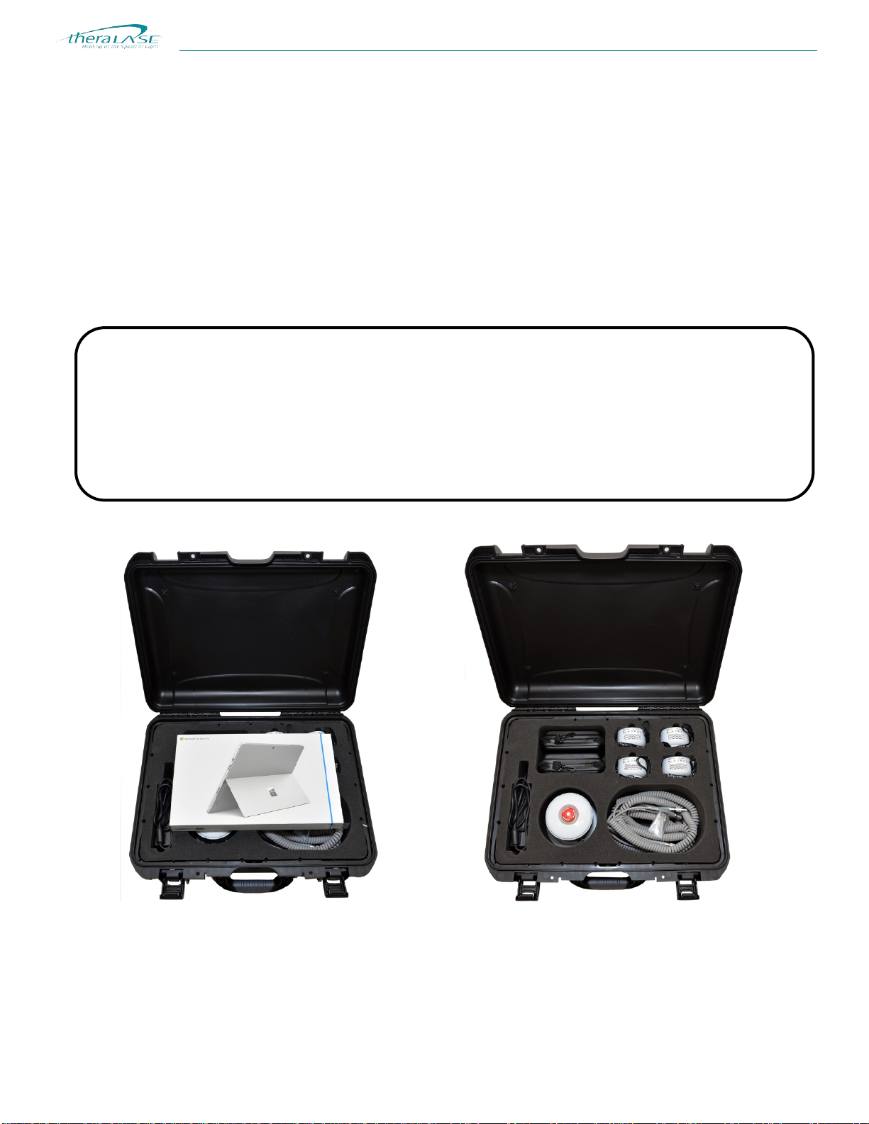
Hard Carrying Case
Top Case Layer Bottom Case Layer
Figure 12. Hard case for TLC-2000 system (part number: TLC-1200).

TLC
-
2
000
THERAPEUTIC MEDICAL LASER
Document: 600-0013
15
Contraindications in the use of Laser Therapy
1.
Do not treat the abdomen of a pregnant woman.
2.
Do not treat any types of neoplasia, cancer or cancerous lesions (benign or malignant).
Cautions in the use of Laser Therapy
1.
Never point the laser in the direction of any person’s eyes.
2.
Do not treat endocrine glands such as the pancreas and the thyroid.
3.
For a new patient or a patient who may be light sensitive, spot test the laser on an area of tissue to determine if they
are adversely sensitive to laser treatment.
4.
If a patient is currently prescribed photosensitive medicine, NSAIDS, steroids or corticosteroid medicine, try to
allow 2 weeks as a wash out period prior to laser treatment. If a wash out period is not possible, reduce the laser
power to 1/2 of the recommended power indicated and increase with each treatment as the patient reliance on
photosensitive, NSAIDS, steroids or corticosteroid medicine reduces.
5.
Start treatment at the most painful area first and follow the treatment specifics. Treat surrounding tissuenext.
6.
Under no circumstances should the patient feel anything more than a slight warming effect. If the patient feels hot
sensations, pain or burning, STOP LASER TREATMENT IMMEDIATELY and check laser equipment. If laser
probe head is hot to the touch, call immediately for service. Detailed contact information is provided in Section 5 -
Maintenance and Service of this manual.
7.
Under no circumstances over-treat an individual, as over-treatment may lead to bio-inhibition of tissuestructures.
TLC
-
2
000
THERAPEUTIC MEDICAL LASER
Document: 600-0013
16
3) START-UP INFORMATION
A detailed description of the individual systemcomponents.
The Power Pack (TLC-2002)
The TLC-2002 Power Pack provides power to each TLC-2001 Laser Probe. The probes’ ports, numbered 1 to 4, are the
same electrical output. A TLC-2001 Laser Probe should always be connected to location #1 first.
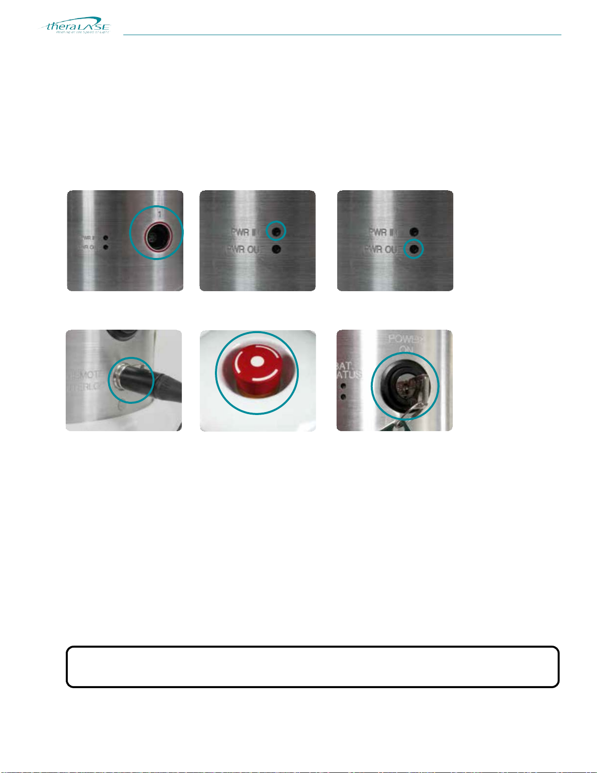
Figure 13. A detailed look at the Power Pack.
1. Remote Interlock Connector: The Remote Interlock Connector is capable of disconnecting the TLC-2001 Laser
Probe(s) from main power when removed. To remove, press the button on the connector and pull the Remote
Interlock Connector straight out. Main power is now disabled and no action will restore it until the Remote Interlock
Connector is replaced.To replace, insert straight into the matching receptacle.
2. Emergency Stop: This button shuts down the entire laser system immediately when pressed, disabling main power.
NOTE: Depressing the Red Emergency Stop Button immediately disables the laser system. Operation
may be resumed by rotating the Red Emergency Stop Button 1/4 of a turn to the right and
allowing it to “pop out” again.
3. Key Switch:This is the main on / off switch for the laser system. When the key is turned to the left, the
system isoff, disabling mains power. When the key is turned ¼turn to the right, the system is on. The key can only be
removed when in the OFF position.
5
4
2
3
1

TLC
-
2
000
THERAPEUTIC MEDICAL LASER
Document: 600-0013
17
Caution: Use only the TLC-2003 Power Supply for the Theralase™ system.
4. Power Supply Input: Input for black DC adapter cord from the TLC-2003 Power Supply. When the DC adapter
is connected the TLC-2000 Power Pack may be operated directly from an AC wall outlet.
5. Probe Power Ports: Power supply ports for up to four (4) TLC-2001 Laser Probes.
6. Power IN LED: This LED is illuminated only when the external power supply is connected and the key switch is in
the ON position, the Remote Interlock Connector is installed and the Emergency Stop is not activated.
7. Power OUT LED: This LED is illuminated only when both of the internal power supply voltages to the probes are
good.
Note: The TLC-2001 Laser Probes will not function if this LED is OFF.
The Laser Probe (TLC-2001)
The Theralase™ TLC-2001 Laser Probe is shown below. A feature of the Laser Probe is the use of a heatsink to keepthe
probe cool during use. There are different strap sizes provided with the Laser Probes to facilitate holding the probe on
different aspects of theknee.
Note: Pressing the black pushbutton on the side of the TLC-2001 Laser Probe will activate the laser diodes.
Pressing the button again will pause laser operation until re-commenced with the same button. After
completion
of a treatment, the pushbutton can be used to repeat the treatment. ARM LED must be
illuminated to commence laser operation.
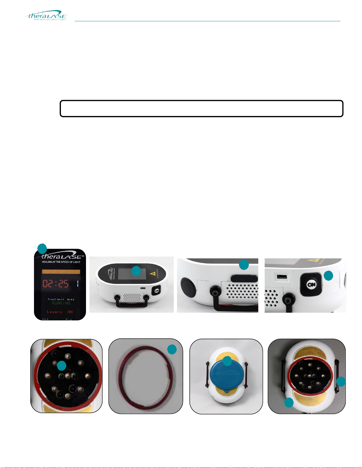
Figure 14. A detailed look at the Laser Probe (TLC-2001).
1. Display: A 2.4” Liquid Crystal Display (“LCD”) is used to display the status of the Laser Probe
(armed/running/paused), laser operation (on/off), BlueTooth® quality, treatment time, number of points treated,
and Laser Probe error messages.
2. Display Window: The display window is made from optically transparent acrylic plastic and can be cleaned with
isopropyl alcohol. Refer to “Guideline for Disinfection and Sterilization in Healthcare Facilities”, 2008, Centers for
Disease Control and Prevention (CDC) for more details.
3. Power On/Off Switch: Slide this switch forward to turn on the Laser Probe. Slide the switch back to turn off the
Laser Probe.
TLC
-
2
000
THERAPEUTIC MEDICAL LASER
Document: 600-0013
18
Caution: NEVER look directly into this area with the lasers on.
4. Start/Stop Button: This button is used to start/stop the Laser Probe laser light emission. Press this button once to
commence emission of laser light. Pressing the button once, while the probe isoperating, will suspend the
countdown and turn off laser emission. The operation and countdown can be resumed by pressing the button in the
correct start sequence again.
5. Laser Diode Aperture: This area is where the laser energy is emitted and is the treatment contact area. There are
five (5) 905 nm invisible, Near Infrared 200 mW maximum average power laser diodes and four (4) 660 nm, visible
100 mW maximum average power, red laser diodes.
6. Laser Output Window: The laser output window is an optically transparent acrylic plastic mounted to a ring.The
window is removable by turning the ring left until it stops and lifting the ring straight off the probe. The window is
coated to be scratch resistant. It keeps the lasers clean and can be wiped with isopropyl alcohol. Windows that
become scratched should be replaced. Replacement windows can be ordered directly from Theralase™.
7. Laser Probe Cover: The Laser Probe cover attaches to the probe by magnets. The cover protects the window
during storage. It is recommended that the cover be installed when the Laser Probe is not in use.
8. Probe Body: The Laser Probe body is molded from Bayblend FR2000, a medical grade, fire retardant PVC
material. This material is impervious to most cleaning and sterilizing solutions, and is cleaned with isopropyl alcohol.
9. Strap Handles: Straps to hold the Laser Probe in place on the treatment area attach to these handles on the sides
of the Laser Probe.
1
3
4
6
5
7
2
8
9
Other manuals for TLC-2000 Series
3
This manual suits for next models
4
Table of contents
Other THERALASE Medical Equipment manuals


