Thermador Professional Series User manual
Installation Insert
GUIDE
IMPORTANT: This insert is in addition to the Installation Guide and is not a substitute. Read and consult the appliance
Installation Guide for important safety messages and additional information regarding the use of your new appliance.
Professional and Masterpiece® Combination Built In Ovens
POM301W, PODMC301W, PODMCW31W,
MEM301WS, MEDMC301WS, MEDMCW31WS
9
Mounting the Speed Oven or
Microwave to the Lower Oven
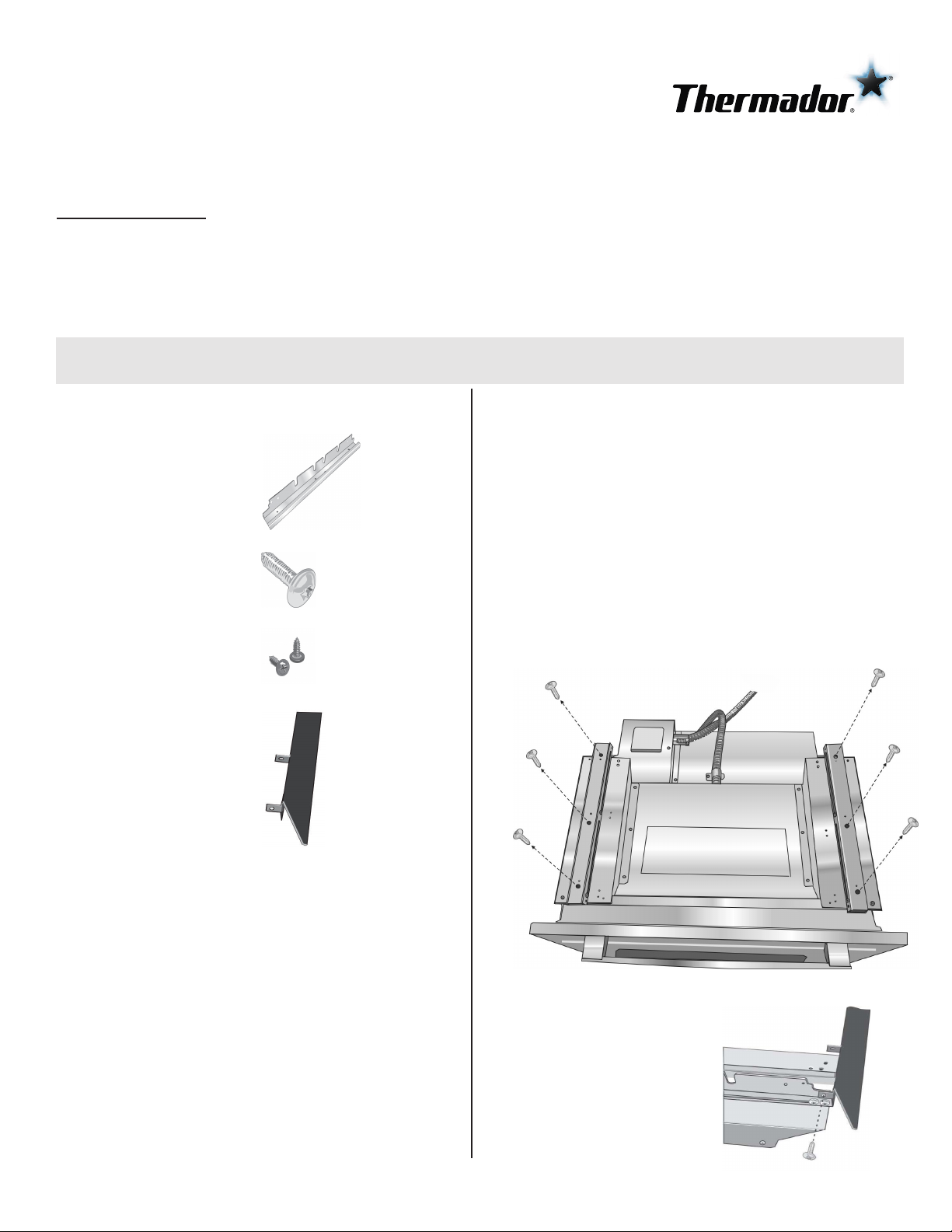
Parts Provided
Universal connector
bracket (2)--in parts box
on top of oven
Screws (16)--in red bag
inside parts box on top
of oven.
Oven Mounting Screws
(8)--screws are included
to secure the oven trim
to the cabinet. The
screws are located in a
small plastic bag affixed
to the literature pack
bag.
Trim Piece--in plastic
bag on top of oven.
Pre-Assembly of the Combination Oven
Combination ovens require the two components to be
assembled prior to installing the combination unit into the
wall cabinet.
Note:
The installation procedures differ between the
microwave and speed oven combination units. The parts
contained in the square tube parts box are common to all
installations.
•
Do not place the oven into the wall cabinet until after
mounting the speed oven on top of the lower oven and
securing it with the universal connector brackets.
•
The universal connector brackets are interchangeable
for the left and right sides of the oven. Be sure the taller
vertical edge of the bracket is positioned to the outside
of the oven.
1. Install both universal connector brackets on top of the
lower oven using six (6) of the screws provided.
Tighten screws securely, but do not overtighten.
2.
Insta ll decorative trim.
Position the decorative
trim piece so the flanges
with the holes in them
face to the rear of the
oven.
Align the outer flanges
with the outside of the
universal brackets. Fasten
with one ( 1 ) screw each
into the end hole of each
universal bracket.
Tighten screws securely,
but do not overtighten.
4. Continue to the corresponding section depending on your
oven type.
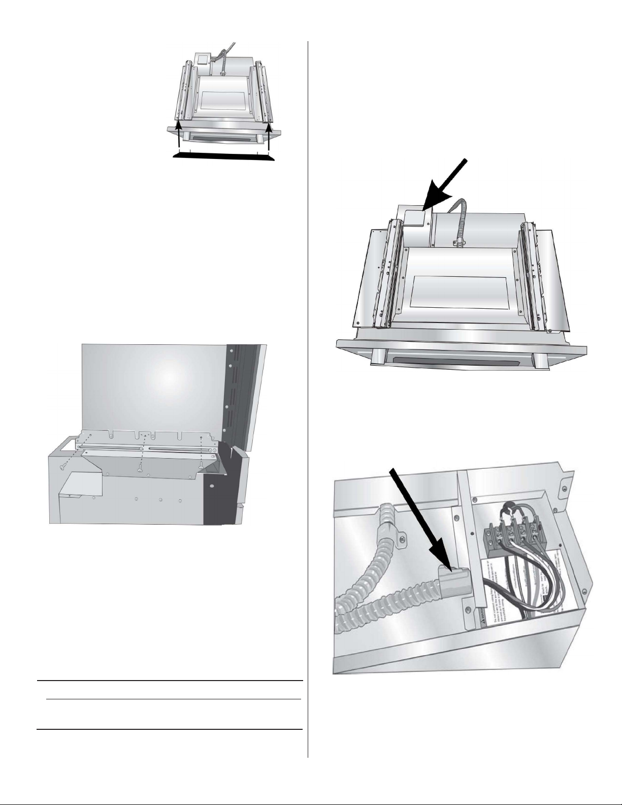
Connecting the Speed Oven to the
Lower Oven
Note:
When installing the combination unit, the speed
oven power cable must be properly attached to the
oven-mounted junction box. This must be done prior to
supplying electrical power to the oven unit.
Check to be sure that no electrical power has
yet been supplied to the oven.
1.
Remove the oven-mounted junction box cover located
on the top rear of the oven. (See image below).
2.
Remove the cap from the conduit access hole in the
side of the oven-mounted junction box.
3.
Guide the wires from the conduit cable (coming from
the speed oven through the hole in the oven-mounted
junction box. (See image below)). There are four wires
from a speed oven.
Speed Oven Models
MEDMC3
0
1WS
PODMC3
0
1W
MEDMCW31WS
PODMCW31W
3. Place the speed oven or microwave unit on top of the
universal connector brackets and fasten in place using
three (3) screws per side. Tighten the screw securely,
but do not overtighten.
Note: The existing screws in the speed oven base
help with alignment. When lowering the speed
oven or microwave into place on the
universal connector brackets, allow these screw
heads to slide into the slots as shown in the
illustration below. The screw nearest the front of
the speed oven or microwave should slide into the
base of the slope at the front of the bracket.
2

See previous illustration in Step 3 for
finished appearance.
6. Replace the oven-mounted junction box cover and
tighten the two screws holding it in place.
Tighten securely, but do not overtignten.
4.
Snap the conduit connector into the hole by pressing it
in until it clicks into place.
5.
Follow the wiring diagram label (see image below) and
match and connect each wire by color to the wires
attached to the wiring block inside the oven-mounted
junction box. Push the bare end of the wire until it is
snug in the wiring block then tighten down the
retaining
screw on each wire.
Tighten securely, but do not overtighten.
Connecting the Microwave to the
Lower Oven
Note:
When installing the combination unit, the
microwave power cord must be properly attached to
the 12
0V
receptacle. This must be done prior to
supplying electrical power to the oven unit.
Check to be sure that no electrical power has
yet been supplied to the oven.
Microwave Models
MEM3
0
1WS
P
O
M301
W
Installation of the Microwave to
the Lower Oven
Plug the microwave power cord into the 120V
receptacle located on top of the lower oven.
(See illustration below.)
Customer Service
The model number and the FD number of your appliance are found on the rating label. Make a note of these
numbers to save time in the event further customer service is needed. Consult your Use and Care Guide for the
specific label location.
To contact Customer Service:
US: 800-735-4328
Web: www.thermador.com/support
Parts & Accessories: www.thermador-eshop.com
3

IMPORTANT: Cet encart est un complément au Guide d’installation; il ne le remplace pas. Veuillez lire et consulter le Guide
d’installation de l’appareil pour d’importants conseils de sécurité et de l’information supplémentaire sur le mode d’emploi de
votre nouveau four.
Fours combinés encastrables Professional et Masterpiece®
POM301W, PODMC301W, PODMCW31W,
MEM301WS, MEDMC301WS, MEDMCW31WS
9
Installation avec four à micro-ondes à
cuisson rapide ou avec four à micro-ondes
Pièces fournies
Support de
raccordement universel
(2) (dans la boîte des
pièces sur le four)
Vis (16) (dans le sac
rouge, à l'intérieur de la
boîte de pièces, sur le
four)
Vis de montage du four 8
vis sont incluses pour
fixer la garniture du four
à l'armoire. Les vis se
trouvent dans un petit
sac en plastique
accroché à la pochette
de documentation.
Pièce de garniture
(dans le sac en plastique
sur le four)
Pré-assemblage de four combiné
Les fours combin
é
s n
é
cessitent l
'
assemblage des unit
é
s
avant que l
'
appareil combin
é
ne puisse
ê
tre install
é
dans l
'
armoire murale.
Remarque: La procédure d'installation diffère entre le four
à micro-ondes à cuisson rapide et le four à micro-ondes
pour les fours combinés. Les pièces contenues dans la
boîte tubulaire de pièces sont communes à toutes les
installations.
•
Installe
z
le four dans l
'
armoire murale uni
q
uement apr
è
s
avoir mont
é
le four
à
micro-ondes
à
cuisson rapide sur le
four inf
é
rieur
à
l
'
aide des supports de raccordement
universels.
•
Les supports de connexion universels sont
interchangeables pour les c
ô
t
é
s gauche et droit du four.
V
eille
z
à
ce
q
ue le bord vertical le plus grand du
support
soit orient
é
vers l
'
ext
é
rieur du four.
1. Installe
z
les deux supports de raccordement
universels sur le dessus du four inf
é
rieur
à
l
'
aide de
six
des vis fournies. Serre
z
les vis
à
fond, mais sans
trop
les serrer.
2. Installez la garniture décorative.
Placez la garniture
décorative de manière à
ce que les brides
comportant les trous
soient tournées vers
l'arrière du four.
4

Aligne
z
les brides
ext
é
rieures avec la partie
ext
é
rieure des supports
universels. Fixe
z
à
l
'
aide
d
'
une vis ins
é
r
é
e dans le
trou
à
l
'
extr
é
mit
é
du
support universel.
Serre
z
les vis
à
fond, mais
sans trop les serrer.
4. Continue
z
à
la section correspondant
à
votre type de four.
Raccordement du four à micro-ondes à
cuisson rapide au four inférieur
Remarque : Lorsque vous installez un appareil
combiné, l e câble d'alimentation du four à micro-ondes
à cuisson rapide doit être branché de manière
adéquate à la boîte de raccordement montée sur l e
four. Cela doit être fait avant de fournir l'alimentation
électrique au four.
A
AVE
R
T
I
SSEME
N
T
Vé
rifie
z
q
ue l
'
alimentation
é
lectri
q
ue du four est
bien coup
é
e.
1
.Enlevez le couvercle de la boîte de raccordement
montée sur le four située sur la partie supérieure du
four, à l'arrière. (Voir l'illustration ci-dessous).
2.
E
nleve
z
le couvercle de l
'
orifice d
'
acc
è
s au conduit sur
le c
ô
t
é
de la bo
î
te de raccordement mont
é
e sur le four.
3.
Guide
z
les fils du c
â
ble de raccordement (venant du
four
à
micro-ondes
à
cuisson rapide
à
travers le trou de
la bo
î
te de raccordement mont
é
e sur le four. (Voir
l
'
illustration ci-dessous). Il y a
q
uatre fils pour un four
à
micro-ondes
à
cuisson rapide.
Modèles de four à micro-ondes
à cuisson rapide
MEDMC3
0
1WS
PODMC3
0
1W
MEDMCW31WS
PODMCW31W
3. Installe
z
le four
à
micro-ondes
à
cuisson rapide ou le
four à micro-ondes sur les supports de raccordement
universels et le fixer en place à l'aide de trois vis pour chaque
côté. Serrez les vis à fond, mais sans trop les serrer.
Remarque: Les vis existantes dans les côtés du four à
micro-ondes à cuisson rapide facilitent
l'alignement. En abaissant le four à micro-ondes à
cuisson rapide ou le four à micro-ondes pour le
mettre en place sur les supports de connexion
universels, laissez les têtes des vis glisser dans les
fentes, comme illustré ci-dessous. La vis la plus
proche de la face avant du four à micro-ondes à
cuisson rapide ou du four à micro-ondes doit glisser
dans la base de la partie inclinée à l'avant du
support.
5
Other manuals for Professional Series
19
This manual suits for next models
7
Table of contents
Languages:
Other Thermador Kitchen Appliance manuals

Thermador
Thermador T18IW900SP User manual

Thermador
Thermador SGS Series User manual

Thermador
Thermador PRD364JDGC User manual

Thermador
Thermador Pro P24 User manual

Thermador
Thermador T18IW902SP User manual

Thermador
Thermador T24IW905SP User manual

Thermador
Thermador T24UW800 User manual

Thermador
Thermador T36BT910NS User manual

Thermador
Thermador Pro Harmony PA30GLBH User manual


