THERMEAU S65 User manual
OWNER’S Manual
PRINTED IN CANADA

2OWNER’S MANUAL
Introduction 3
General Safety Instructions 5
Thermeau Models’ Specifications 7
Installation Instructions
Location 9
Water piping 10
Multiple Heat Pump Connections 11
Electrical 12
Bonding 12
Bonding and plumbing step-by-step instructions 12
Electrical Connections 13
Electrical Diagrams 14
Service Analyzer Control 15
Electronic Temp. Controls 16
Initial Startup 18
Meaning of Display Codes 19
Troubleshooting 20
Requesting Assistance or Service 22
Maintenance 22
Winterizing 22
Pool Heat Pump Warranty 23
Table of contents

3
OWNER’S MANUAL
Thank you for buying
an THERMEAU pool heat pump.
The THERMEAU pool heat pump is a self-contained unit designed specifically
for pool heating. Each component has been selected with care to achieve a
high-quality product in an effort to exceed all industry standards.
All THERMEAU pool heat pumps have a Scrollcompressor, an electronic board
with service analyzer, a titanium heat exchanger tube warranted for 10 years
against corrosion. All components are of superior quality, which presents you
with an effective, state-of-the-art technology heat pump.
In general, compared to other types of pool heaters, such as gas or oil-
fired, the THERMEAU pool heat pump has a lower heating capacity on a
BTU/hr basis. Therefore, it needs to operate for a longer time to accomplish
the desired results. Occasionally, it may be necessary to run the heat pump for
up to 24 hours per day. However, this should not be of concern to the owner
because the heater is designed to operate continuously. What’s more, despite
continuous operation, it will still heat the pool far more economically than other
types of heaters.

4OWNER’S MANUAL
Service can now be obtained by calling
these phone numbers.
CANADA: 1 855 661-9330
USA: 1 855 385-6480
Please read carefully
Whenever you call to request service for your heater, you must know your
complete model and serial numbers. You can find this information on the
name plate located on the right side of your heater.
Please also record the purchase date of your device and your dealer’s name,
address, and telephone number.
Model Number ____________________________________________________
Serial Number _____________________________________________________
Purchase Date ____________________________________________________
Dealer Name ______________________________________________________
Dealer Address ____________________________________________________
Dealer Phone _____________________________________________________
Keep this book and the sales slip together in a safe place for future reference.
5
OWNER’S MANUAL
General Safety Instructions
We care for our customers
We have provided important safety messages in this manual and on your
heater. Always read and obey all safety messages.
IMPORTANT
The IMPORTANT sign calls attention to a note that provides important
information or information essential to the completion of a task.
CAUTION
The CAUTION sign denotes a hazard. It calls attention to an operating
procedure, practice, or the like, which, if not correctly performed or
adhered to, could result in material damage, particularly to the product,
up to the destruction of part or all of the product.
WARNING
The WARNING sign denotes a hazard. It calls attention to a procedure,
practice, or the like, which, if not correctly performed or adhered to,
could result in personal injury or injury to a third party. These signs are
rare, but are extremely important.
?
!

6OWNER’S MANUAL
CAUTION
All electrical connections must be done by a qualified electrician and
according to the local electrical codes. Always cut off the unit’s main
power whenever the access panel is open or removed. Always install the
machine outdoors (unless otherwise approved by the manufacturer),
while respecting the minimal clearances needed for proper operation
and heating.
!
CAUTION
Proper pool chemistry is vital to the life of your heater. Pay particular
attention to the total alkalinity and TDS. It is highly recommended that you
have your pool chemistry checked often by an independent pool store.
!
Water quality standards that must be strictly observed
Description Normal Range Verification
pH level 7.2 to 7.8 Once/week
Chlorine concentration 1.0 to 3.0 ppm Once/2-3 days
Total alkalinity 80 to 100 ppm Once/2-3 weeks
Total dissolved solids (TDS) Below 1600 ppm (fresh water) Once/month
Below 3000 ppm (salt water) Once/month
Calcium hardness 200 to 300 ppm Once/month

7
OWNER’S MANUAL
A robust and reliable product line
Residential
OPERATING
SPEcIfIcATIONS S65 / TH65 S80 / TH80 S100 / TH100 S125 / TH125 S140 / TH140
Volts 230 230 230 230 230
Hertz 60 60 60 60 60
Phase 1 1 1 1 1
Compressor amps 12.4 A 14.3 A 21.2 A 24.3 A 27.3 A
Fan motor max.
load amps 2,4 A 2,4 A 2,4 A 2,4 A 2,4 A
Fan motor HP 1/3 1/3 1/3 1/3 1/3
Fan motor speed 825RPM 825RPM 825RPM 825RPM 825RPM
Minimum circuit
ampacity 30 A 30 A 40 A 40 A 50 A
Maximum fuse 40 A 50 A 60 A 60 A 70 A
Refrigerant R-410A R-410A R-410A R-410A R-410A
Optimal water flow
rate (GPM) 30 35 40 55 60
Max. water flow
rate (GPM) 100 100 100 100 100
Max. water
temperature 104F 104F 104F 104F 104F
Dimensions (in.) H:34 L:33 D:39 H:34 L:33 D:39 H:34 L:33 D:39 H:34 L:33 D:39 H:34 L:33 D:39

8OWNER’S MANUAL
A robust and reliable product line
Commercial
MOdEl TH-200 TH-200-3 TH-200-3A
Compressor ( HP ) 2x5 10 10
Compressor type Scroll Scroll Scroll
Heat exchanger Titanium / PVC Titanium / PVC Titanium / PVC
Heating range
(°F / °C)
Up to
104°F / 40°C
Up to
104°F / 40°C
Up to
104°F / 40°C
Voltage Hz/Ph 208-240 60/1 208-240 60/3 575-600 60/3
Required breaker 60 60 30
Minimum circuit ampacity
(MCA) 47 44 16.8
Plumbing connections 2’’ 2’’ 2’’
Water Flow (GPM) 60 to 125 60 to 125 60 to 125
Dimensions in inches
H: 48
W: 33
D: 39
H: 48
W: 33
D: 39
H: 48
W: 33
D: 39
Hot Gas Defrost Yes Ye s Yes
Weight (lb) 445 375 375

9
OWNER’S MANUAL
IMPORTANT
?
Installation Instructions
Location
The placement of the pool heater is very important in keeping installation
costs to a minimum while providing for maximum efficiency of operation, as
well as allowing adequate access for service and maintenance.
The THERMEAU pool heat pump is designed for outdoor installation and
should not be installed in a fully enclosed area, such as a shed, garage, etc.,
unless ventilation is provided to ensure adequate air exchange for proper
operation. Recirculation of cold discharged air back into the evaporator coil
will greatly reduce unit heating capacity and efficiency.
The unit should be located as close as practical to the existing pool pump and
filter to minimize water piping. However, do not forget to provide a 18” clear-
ance at the very least all around your heat pump.
Mount the unit on a sturdy base, preferably a concrete slab or a set of blocks.
The size of the base should not be less than 40” x 40” (100 cm x 100 cm).
All THERMEAU pool heat pump models feature patented, ultrasilent ventilation
systems. Air is pulled through the evaporator coil and discharged through the
top grille. A minimum clearance of 48 inches should be allowed above the unit
for unrestricted air discharge. The unit must not be installed under a porch. Any
side of the unit should be located at least 24 inches from a wall or from any
other obstruction for unrestricted air intake and service access.
Fig. 1

10 OWNER’S MANUAL
IMPORTANT
?
Fig. 2
Water piping
The piping sequence is as follows: pool pump > filter > heater > pool. Auto-
mated chlorine distribution systems, if used, must be placed downstream of
the heater to minimize harm to the pool equipment. Use rigid PVC piping if
possible (SCH40 or SCH80). All joints should be glued with PVC glue. If rigid
PVC is not available, you can use soft or flexible piping with stainless steel
clamps. When the piping installation is complete, operate the pool pump and
check the system for leaks. Then, check the filter pressure gauge to verify
that there isn’t any indication of excessive pump head pressure.
You can also make the connections using high-pressure flexible hose, but
make sure the hose can withstand high pressure. The installation of a bypass
is not necessary unless the water flow exceeds 125 GPM.
11
OWNER’S MANUAL
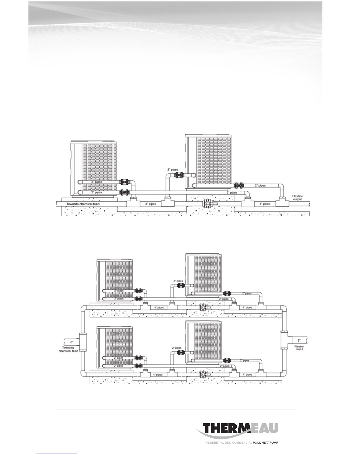
Fig. 3
Fig. 4
Multiple Heat Pump Connections
All plumbing on multiple heat pump installations must be done in parallel. An
equal flow of water to each heat pump is important for optimum operation.
NOTE: It may be necessary to adjust water pressure switch if a unit is installed
below the water level.
Each heat pump allows a maximum flow rate of 125 gpm (473 L/min) and
requires a minimum of 60 gpm (227 L/min).
12 OWNER’S MANUAL
Electrical
The wiring of your THERMEAU pool heat pump should be performed by a
qualified electrician in accordance with local requirements.
The unit must always be deactivated before opening the access panel.
Bonding
Because all metals have different electrical potentials, all metal and electrical
components of the pool system must be bonded together. This includes the
metal framework of the pool, the light, the pump, the filter (if made out of metal),
the heater, any automatic chlorine generator, and any other metal or electrical
equipment. On some older pools, this substructure bond wire may not exist.
In these cases, a 6 to 8 foot solid copper rod must be driven into the ground
near the equipment. All electric and metal components must then be bonded
to each other, and then to the copper rod.
WARNING
!
1. A 1/3 lb check valve must be installed between the heater
and any automatic chlorine distribution system (if used).
2. Any kind of automatic chlorine distribution system must be
installed after or downstream of the heat pump.
3. The filter must be placed before or upstream
from the heat pump.
Bonding and Plumbing
step-by-step instructions
CAUTION
!
WARNING

13
OWNER’S MANUAL
3 Phase loss and reversal protection
Operating mode:
The THERMEAU unit is equipped with SCROLL
compressor which cannot run in both rotations.
When the heating light on the main board will come
on, If all three phase are relatively equal and in pro-
per sequence, the (ON) green light on the phase
protector will be energize and the compressor will
start normally. If the phase are in wrong sequence,
that’ll be the (FAULT) red light that come ON and the
compressor won’t start. If this occurred, you have to
switch the L1 wire with L2 wire.
WARNING
L3 L2 L2L1 L1
Ground Ground
ON FAULT
Electrical Connections
The installation of the THERMEAU pool heater should be performed by a cer-
tified electrician. To connect the electricity, you must unscrew the four screws
of the front panel, then slide the electric cable in the hole located on the left
or the right side of the base, and then insert it in the control box. The electrical
diagram is located on the lid of the control box as well as below.
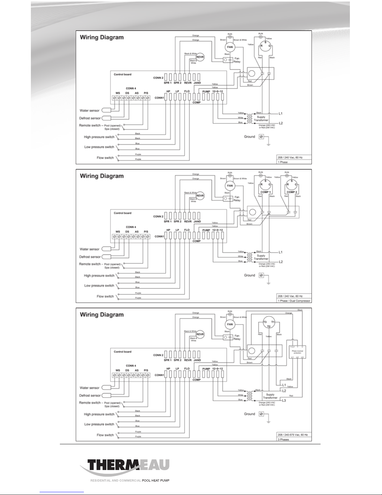
14 OWNER’S MANUAL

15
OWNER’S MANUAL
Temperature
and parameter
display
Access
to parameters
Heating mode
Compressor running
Heating mode
To raise the desired
temperature or to
change parameters
To lower the desired
temperature or to
change parameters
Service Analyzer Control
The control panel is factory set to display the temperature in Fahrenheit degrees.
Fig. 5

16 OWNER’S MANUAL
Electronic Temp. Controls
All units
Description
The control located on the front of your heat pump has a large three-character
display for the water temperature, set points, and diagnostics (see figure 5
for front panel appearance). The three button keypad includes SET, DOWN
arrow, and UP arrow buttons. LED indicators next to the display show if the
heat pump is in the pool mode or in the spa mode and if the unit is running.
Buttons:
Press the SET button to change between modes and use the up and down
arrows to change the selected mode’s settings.
Modes available are :
POOL Allows you to change the pool water temperature set point.
SPA Allows you to change the spa water temperature set point.
P-S Changes between pool and spa settings. LED’s on front panel will
indicate current mode selected.
C-F Display temperature in Fahrenheit or Celsius.
Water Temperature Set Point
Temperature set point range is OFF, and 61°F to 95°F for POL mode. For SPA
mode, set point range is OFF, and 61°F to 104°F. Pushing the UP arrow or
DOWN arrow buttons will prompt the control to display the current set point.
Continuing to press the UP or DOWN buttons will allow the set point values to
scroll until the desired set point is reached. Once the new set point has been
reached, stop pressing the UP or DOWN buttons. Once the unit toggles back
to the current water temperature display, the set point is entered. The controls
have a feature called « Set Point Memory Retention ». If the power is removed
from the unit, it retains the last set point displayed.

17
OWNER’S MANUAL
Connecting to a Remote System
This Pool Heater is compatible with most of all known remote systems in the
industry. The following models’ diagrams show how to connect all of the remote
systems to the Electronic Temp. Controller.
For 2 wire remotes
1. Bring up « POL » setting and arrow temperature down until pool setting
reads « off ».
2. Bring up « SPA » setting and arrow temperature up until spa setting reads 104.
3. Set unit to the « POL » mode.
4. Connect remote system with 2 wires to the P/S terminal on control board.
Figure 6 shows you where to connect the 2 wire remote systems to the
temperature controller.
For 3 wire remotes
1. Bring up « POL » setting and use arrows to select desired pool temperature.
2. Bring up « SPA » setting and use the arrows to select the desired spa tem-
perature.
3. Set unit to « POL » mode.
4. Connect the commun and high (or spa) wires to the « P/S » terminals on
control board (see specific model diagram). Low or pool wire does not get
connected.
Fig. 6

18 OWNER’S MANUAL
IMPORTANT
?
Initial Startup
Before starting the pool heater for the first time, it is important to verify that
the breaker is in the ON position.
Also make sure that the water circulates freely and that the pool pump is activited.
Then, you will need to set the water temperature you desire. The fan will
immediately start. The compressor will start after a 3 to 4-minute delay.
When the compressor is running, the HEATING/CHAUFFAGE indicator located
on the right (see “Service Analyzer Control,” p.15) should be lit. At initial startup,
it is normal for the unit to run 24 hours a day.
It is also normal to see water dripping from the holes at the base of the unit.
This is simple condensation.
Connection to AquaLink, Compool, Hayward, AquaLogic or any other 2 wire
remote system with their own thermostat :
• Removegrayjumperfromterminals1and2onTB1
• Bringthetwowiresfromtheremotesystemtoterminals1&2onTerminal
Block 1 (TB1)
• TheTemperatureControlknobmustbeturnedclockwise(highesttemp.
setting) for the remote system to operate the Pool Heater properly.
19
OWNER’S MANUAL
Meaning of Display Codes
Service Analyzer Codes
Most problems will be detected by the service analyzer and a code will be
displayed on the digital display of your heater.
Display Meaning of codes
OFF The desired programmed temperature point is lower than 60°F (15°C).
LP & LP3 Shortage of refrigerant gas in the unit or faulty low pressure
control. The digital display will show LP3 after 3 LP faults and shut
down your pool heater. The pool pump will also be stopped for pro-
tection if the unit’s internal time clock feature is used. If LP or LP3
occurs you should call for service.
HP & HP3
Low water flow TO the unit or faulty high pressure control. Check
water flow. Backwash filter and/or heater. The unit will show HP3
after 3 HP faults. This will stop your heater for protection.
Po Water temperature probe connected to #1 and #2 on electronic board
may be disconnected. If it is not, the probe may be open or defective.
Pc Water temperature probe is short circuited or may be defective.
FLo & FL3
Possible causes:
- The FIL parameter must always be set to OFF.
- The filter is in backwash position.
- The filter pump is stopped.
- The filter is dirty.
- Shortage of water to pool pump.
- Water pressure switch must be adjusted or it is broken.
- The unit is in the protection mode and will show FL3, press
any key to restart the unit. FL3 code will stop your heater for
protection.
dPo Suction temperature probe connected to #3 and #4 on electronic
board may be disconnected. If it is not, the probe may be open or
defective.
dPc
Suction temperature probe is short circuited or may be defective.
FS
Unit currently in defrosting cycle (the fan works but the compressor
is stopped). This is normal operation when outside temperatures
are cold.
20 OWNER’S MANUAL
Troubleshooting
The heat pump is in protection
mode.
The unit is on defrost
cycle.
In this case, there may be
a 5-minute delay before
restarting.
Digital display should indicate FS.
The compressor will automatically
start again a few minutes after the
display stops indicating FS.
The fan is running, but the compressor is not.
Pool pump is not running.
Filter is dirty, restricting
the water flow.
Turn the pool pump on.
Backwash and clean filter.
The heater is displaying “o” and it will not start.
Heat pump control set to OFF.
Desired water temperature
is reached.
Main breaker is tripped.
Raise temperature set point above
60°F (15°C).
Unit will automatically restart
when the water temperature goes
below the set point.
Reset it.
The pool heater is not running.
This manual suits for next models
12
Table of contents
Other THERMEAU Swimming Pool Pump manuals

Popular Swimming Pool Pump manuals by other brands

Pentair
Pentair STA-RITE SWIMMEY Series instruction manual

Elecro Engineering
Elecro Engineering Swimming Pool Heat Pump Owner's installation & operations manual

Wayne
Wayne WAPC250 Operating instructions and parts manual

Intex
Intex 128366NP owner's manual

Kripsol
Kripsol KS Evo VS 150 user guide

COMFORTPOOL
COMFORTPOOL FUZZYCLEAN manual


