APF VIPOOL MJB VSD Owner's manual

INFORMATION,SETTINGS
swimming pool pump
MJB VSD

2VSD Pump - June 17
INDEX
INFORMATION
1. Meaning of symbols P. 3
2.A General safety instructions P. 4
2.B Operating precautions P. 4
3.A Hydraulic connections P. 5
3.B Electrical connections P. 5
4. Control of the pump P. 5
5. Operating of pump terminal box P. 7
6. Operating of the remote box (option) P. 10
6.B Additionnal functions : THG et OME P. 12
7. Precautions P. 14
8. Intervention on the pump P. 14
9. Wintering P. 14
10. Possible defects, causes and solutions P. 15
Adjustment notes P. 15

3
About MJB VSD
> DESCRIPTION
- Economical pump with programmable speed as required.
- Ergonomic : the pump includes a control keypad and a display
Digital LED for easy programming and control.
- Visual control keypad with 5 colored keys :
• 3 keys : setting of the programmed speeds (2000, 2400 and 2850 rpm), pre
Recorded and modulable from 1000 to 2850 rpm.
• 1 key : on and off.
• 1 key to access the menu.
- Timer included for self-priming.
- Delivered with unions.
DANGER Risk of electric shock.
DANGER Risk of injury to persons.
ATTENTION Risk of damage to pump and installation.
1. MEANING OF SYMBOLS

4VSD Pump - June 17
The instructions listed below are purely indicative and in no way limited. The pump must always
be handled with the most care.
▪ The pump was designed for use in a closed circuit, in clean water at a temperature between 5° C and 50° C.
▪ Do not modify the pump in any way ; the guarantee will automatically be invalidated in the event of a pump
modication.
▪ For all repair work, only use spare parts supplied by the manufacturer; the latter will not be held liable in the event
of damage caused by the use of non-original spare parts or parts which have been modied without prior approval of
the manufacturer.
▪ The safety and correct operation of the pump are guaranteed only if all the installation and commissioning
instructions have been followed.
▪ The pump must be installed in compliance with the applicable standards in force in the country of installation and
use, especially HD 384.7.702; we recommend you contact a professional for the pump installation.
▪ Cut off the electricity supply to the pump prior to any intervention.
▪ The limits specied in the technical data table must never be exceeded under any circumstances.
▪ In the event of a malfunction or failure, please contact your nearest manufacturer’s representative or the
manufacturer’s Technical Support Service.
▪ Hot surface in the area around the motor.
This document contains basic information for the safety of persons and property, as well as the start-up of the
pump. The user and the installer must read the information contained in this document before installation and
commissioning. This reference document must be kept.
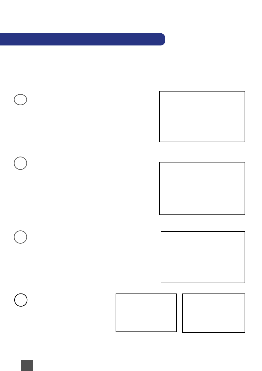
▪ Never operate the pump without the prelter.
▪ Never operate the pump without any water.
▪ Your pump is tted with a prelter basket designed to collect any large impurities which could damage
the turbine.
▪ To ensure the correct operation of the pump:
- Always operate the pump with the prelter in place,
- The pump must be installed horizontally and secured in place.
▪ Its performance is optimized if the pump is positioned below the swimming pool’s water level.
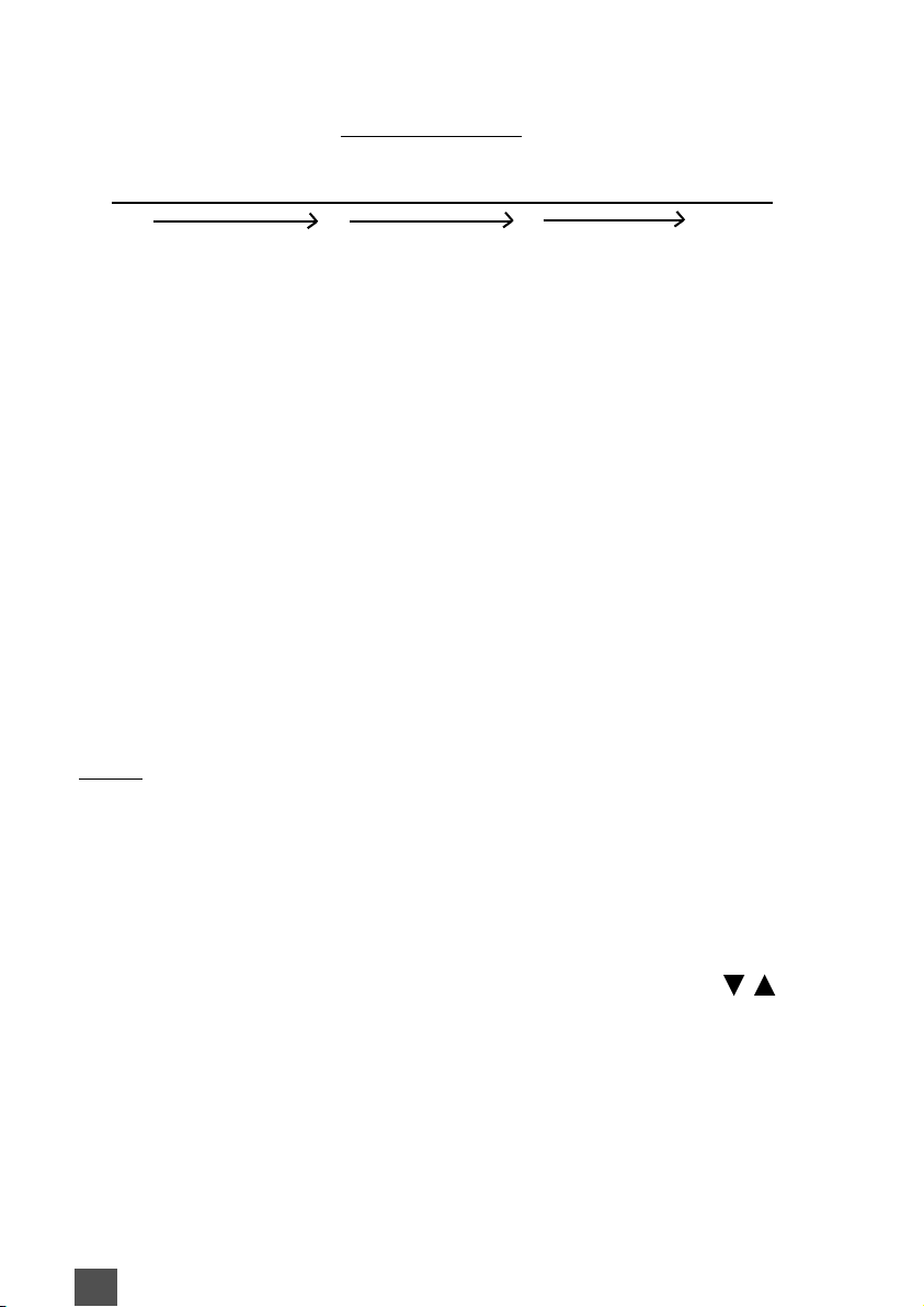
▪ If the pump has to be installed above the swimming pool’s
water level, the height must not exceed 1,5 m and the length
of the suction pipe will have to be as short as possible in
order to avoid signicant suction times and pressure losses
(diagram).
▪ For the correct air circulation and to ensure effective
cooling,the fan grid must be located more than 30cm from
Drawing n°1
Max = 2 m
2. SAFETY INSTRUCTIONS
A. For the pump
B. Operating Precautions

5
3. CONNECTIONS
A - Hydraulic connections
• Connect the pump to the swimming pool’s hydraulic circuit using the couplings provided.
• To connect the pipes to the pump, the joints are supplied with O-rings which must under all
circumstances be used.
• The pipes must be connected to the couplings and glued in place.
• The delivery pipe must be tted at a right angle and perfectly centered with respect to the
outlets to be connected, so as to avoid the pump and pipe from being subjected to external
stresses which could cause them to break, irrespective of the assembly operations. We
recommend a vertical pipe length of approx. 60cm to facilitate the priming of the pump.
• Une légère inclinaison des tuyaux
d’aspiraon (2%) évite la formaon de
poche d’air.
60
3. B Electric Connections
The pump is equipped with a 3mL cable ending with a plug
Single phase 230V AC.
4. CONTROL OF THE PUMP
3 possible start-up possibilies, via:
A - pump only via its touch control pad with screen.
B - pump and 5 wire cable, ref: C5FVS.
C - the remote box *, ref: B01P0232.
*opon.

6VSD Pump - June 17
A. Inseron of the 5 connecon wires cable pump:
- Open the terminal box of the pump,
- Remove the plug (on the side of the pump housing),
- Screw the cable clamp onto the pump housing.
- Place the connector on the card,
- Pass the cable clamp, from the inside to the outside.
- Tighten the «cable clamp» nut.
- Close the housing.
Possible wiring at the end of the 5-wire cable :
GND = common = Black wire
By connecng : Black / Brown = speed 1
Black / Green = speed 2
Black / White = speed 3
Black / Red = Stop
B. Connecng the remote box *
- Open the housing,
- Pass the end of the cable into one of the wire cable,
- Connect the 5 wires of the cable in the housing (see diagram
below),
- Close the housing,
- Insert the transformer plug into the socket on the housing,
- Fix the housing at height,
- Connect the supplied power
supply of the remote unit to a 230 V
socket.
* Oponal
Supplied with shunt
GND V1 V2 V3 STOP
Noir Marron Vert Blanc Rouge
Black Brown Green White Red

7
5. OPERATING OF PUMP TERMINAL
BOX
A.Default sengs :
Speed 3 = 2850 rpm
Speed 2 = 2400 rpm
Speed 1 = 2000 rpm
Priming speed : = 2850 rpm
Priming me : = 5 minutes
Adjustable speeds : 1000 - 2850 rpm in increments of 50 rpm.
Adjustable priming me : 0 to 10 minutes ( by 1 minute steps).
B. User interface :
(A) Led screen: displays the engine
speed.
(B) «SET» key: accesses the programming
mode or resets the command.
(C) «1 » key: selects the xed speed 1 or
changes it in programming mode.
(D) «2 / OK» key selects the xed speed 2
or saves it in programming mode.
(E) «3 » key: selects the xed speed 3 or
changes it in programming mode.
(F) «0» key: Stops the motor.
A
B
F
C
D
E

8VSD Pump - June 17
Funcons priories:
Low High
V1 V2 V3 STOP et
OFF
C. Operaon
- Press one of the «1», «2» or «3» keys to select the preset
xed speed. If the pump is triggered aer a shutdown
period, it will then start in the priming mode and then move
to the xed speed selected. As long as the pump is in the
start-up phase, the selected speed LED ashes. Otherwise,
it starts directly at the determined speed, without going
through the iniang step.
-To stop the motor, press the «0» key. The «Power» LED
ashes, and the screen shows «OFF».
Noce : When the MJB-VSD is used with the remote control unit, the connecon
to the control unit must be shut down, or unplugged from electrical supply before
seng the speed or priming duraon.
D. Fixed speed sengs
- Press the xed speed key to modify, and keep it pressed
at least 3 seconds, unl the speed on the screen blinks. The
speed can, now be modied with the keys : « ».
-To memorize a favorite speed, you must press “OK”. To
invalidate your choice, and keep the original speed, press
“s et ”.
Note: During the suction phase, the pump speed can
not be changed.

9
E. Priming sengs
The engine should be shut o (O buon) to set the
priming speed. Keep the “set” buon, pressed at least
3 seconds, unl the speed on the screen is blinking.
The starng speed during priming can be chosen, using
the keys and memorized with “OK” key. Once priming
speed is set, the priming duraon can be dened, and
set between 0 (o) and 10 minutes priming.
F. Reset
To restore the factory sengs to the motor, hold down
the «SET» buon for about 15 seconds. The motor
stops, and the three xed speed LEDs light up. The dis-
play of the control unit switches o aer 3 minutes of
inacvity, except in the event that the external control
unit for example sends a signal to the pump every mi-
nute.
In the event of a power failure, the pump automacally
restarts at the last set speed, or remains o in the event
that it has been stopped beforehand.

10 VSD Pump - June 17
Main screen :
•day /month /Year
•hour
•Speed in operation : 1/2/3
•Program in function : Prog 1 / Prog 2 / MANU
By pressing the MENU button :
Access to settings :
•Date / time : to be configured with the arrows.
•Program : configuration of the program (see
next section).
•Return
Vary with the touchpad arrows.
Input screen in the program :
• Select program 1 or 2 for settings.
• Choose the arrows and press « OK » for
validation.
Screens for choosing daily or
weekly settings.
1
2
3
4
6.Operation of the remote control unit (option)
The housing consists in a screen and a touch pad
with 5 keys :
4 navigaon and 1 central «Menu / OK» key.
Plug in the housing, it will light up on the main
screen.

11
Display shows : day and hourly
programmed speeds (0 to 12 hours and 12
to 24 hours per 1 hour interval in 1 hour).
O = Off (no filtration)
= Speed 1
= Speed 2
= Speed 3
Programming speeds according to the
hours on a weekly basis.
5
6

12 VSD Pump - June 17
-2 addional cable glands are supplied in the housing ref: B01P0232
- In case you use opons, they must be added to the case.
To do this, drill the box Ø9mm to put these cables in place.
• Freeze protecon
The frost-free thermostat (ref: THG), must be connected directly to the
terminal block (on the right) of the housing (see illustraon p.6 ).
The switch-on point (low temperature) must be set on the THG. This
allows the pump to start in V1 so as to prevent from freezing.
To do this, rotate the scroll wheel to the posion.
•Lack of water opon
This opon is composed of a 50 x 1’1 / 2 support collar and a ow sensor.
-The collar is to be posioned on the pipe, at the pump outlet. For this
purpose, the hose must be drilled Ø18mm.
-Screw the sensor in the direcon of ow.
-Connect the sensor wire to the terminal block instead of the
shunt.
-The delay in case of absence of ow is 5mn before the stop of the pump.
Drilling of the cable
gland housing.
THG
OME
6.B Added functions on remote box

13
Overview of operaon and possible error messages
In the event of an error, the motor stops permanently. Excepon error : «Undervoltage»
(insucient voltage). The motor restarts automacally as soon as the voltage becomes
greater than 209 V for at least 6 seconds.
If an error occurs, the system power must be turned o.
Drilling of the cable
gland housing.

14 VSD Pump - June 17
7. CAUTIONS ON OPERATING THE PUMP
▪ The pump should operate without making any noise or vibrations.
▪ Check for any leaks on a regular basis.
▪ Clean the prelter basket on a regular basis.
▪ Always stop the pump before handling the valve on your lter (6-way) on the
swimming pool’s hydraulic circuit.
▪ This electrical pool pump is tted as standard with a exible lter bag inserted
in the pre-lter basket. This is intended to trap ne impurities (gravel, sand, pine
needles, etc.) which can often prevent pumps from operating correctly. When
using the pump for the rst time, when there is sand or pine needles present in
the pool, or if a manual broom has been used, these are situations where the use
of the exible lter bag is essential. We therefore advise you to leave this option
permanently in position and, of course, to check and clean it regularly (at least once a week).
If the electrical pump is returned to us for aer-sales service due to a blockage of the turbine from impuries larger
than the exible lter bag’s straining capability, the item will not be repaired under warranty.
You can obtain addional exible lter bags from your usual supplier.
Risk of injury to persons without the required qualications. Repair and maintenance work must be carried
out by specially trained personnel.
▪ When working on the pump :
- Cut off the electricity supply
- Make sure the switch is set to “off”
- Wait for the motor to have come to a complete stop.
▪ The mechanical seal is a vital component of the pump. It should be replaced with the utmost care. It is
advisable to contact a specialist for this task.
▪ Disassembly/Re-assembly: Take the necessary precautions to avoid trapping your hands or feet.
- Clean and check all parts before reassembling them.
- Replace all worn or damaged parts (imperative).
- Make sure the seals are clean and in the correct position. We recommend you only reposition new seals.
▪ In all spare part orders, please specify: the type of pump (data plate), the pump’s serial number (data
plate), the part’s position number (exploded view), the name of the part (table and exploded view).
9. HIVERNAGE
9. WINTERING
▪ The pump must be emptied out through the plughole for anti-freezing
purposes.
Prelter basket Flexible pocket lter®
8. INTERVENTION ON THE PUMP

15
10. TROUBLESHOOTING
NOTES FOR ADJUSTEMENTS
FAULTS PROBABLE CAUSES SOLUTIONS
• The pump doesn’t prime. Air leak along the suction
pipe.
Incorrect motor revolution
direction (three-phase motor).
Check the condition of the
couplings and seals along the
suction pipe.
Invert 2 phases on the
electricity supply.
• Weak pump output. Pressure loss in the suction. Check the condition of the
couplings and seals along the
suction pipe.
Avoid : long pipes, numerous
elbows, positioning the pump
higher than the water level,
narrow pipes.

Table of contents
Popular Swimming Pool Pump manuals by other brands

Espa
Espa MULTIPOOL PLUS instruction manual

Intex
Intex krystal clear 602 owner's manual

pumpa
pumpa BLUE LINE PFC505 Original instruction manual

Pentair Pool Products
Pentair Pool Products Pump Waterfall Operation and service manual

poolstar
poolstar STAR PUMP 7 Operation instructions

Lark
Lark SKIMMERPLUS SFX330 owner's manual