Thermia Expansion module 1 User manual

Installation Guide
Expansion module 1
C
OK

Thermia Värmepumpar is not liable or bound by warranty if these
instructions are not adhered to during installation or service.
The English language is used for the original instructions.
Other languages are a translation of the original instructions.
(Directive 2006/42/EC)
© Copyright Thermia Värmepumpar

Table of Contents
1 Important information/Safety instructions ............................................... 4
1.1 General safety precautions ....................................................... 4
1.2 Electrical connection ........................................................... 4
2Components and hardware specifications ............................................... 5
2.1 Mounting the box ............................................................. 5
2.2 Components ................................................................ 6
2.3 Connecting to accessory bus ...................................................... 7
2.4 Hardware specifications ......................................................... 8
3System solutions ................................................................. 9
3.1 Connections ................................................................ 9
3.2 Distribution circuit 2-5 .......................................................... 10
3.3 TWC/WCS .................................................................. 13
3.4 Cooling/Cooling2 ............................................................. 14
3.5 Pool ...................................................................... 15
3.6 Legacy .................................................................... 17
4 Configuring the module ............................................................ 20
4.1 Language selection ............................................................ 20
4.2 Software selection/Set unit ID ..................................................... 21
5 Manual test .................................................................... 22
5.1 Manual test set up ............................................................. 22
5.2 Table of functions ............................................................. 23
Installation Guide Expansion module 1
Thermia Värmepumpar VQILV502 3

1 Important information/Safety instructions
1.1 General safety precautions
Warning This appliance can be used by children aged 8 years and above, and
by persons with reduced physical, sensory or mental capabilities or
lack of experience or knowledge, provided that they are supervised or
have been instructed in the safe use of the appliance and understand
the hazards involved. Children must not clean or carry out user main-
tenance on the appliance except under adult supervision.
Warning Risk of personal injury! Children are not permitted to play with the
product.
1.2 Electrical connection
Danger Hazardous electrical voltage! The terminal blocks are live and cause
death through electric shock. All power supplies must be isolated be-
fore electrical installation is started.
Warning Electrical installation may only be carried out by an authorized electri-
cian and must follow applicable local and national regulations (IEC
60335-2-40).
Caution It must be possible to isolate the power supply using an all-pole circuit
breaker with a minimum contact gap of 3 mm.
Installation Guide Expansion module 1
VQILV502 Thermia Värmepumpar
4

2 Components and hardware specifications
2.1 Mounting the box
1. Open the lid by turning the knob counter clockwise. 2. Unmount the front by loosen the screws in each corner.
3. Mount the box on the wall by using the designated markings
on the inner back side of the box. Use screws and plugs (not in-
cluded) that are dimensioned to hold the weight of the box (5
kg).
P1 RxTx
P/B
P2 RxTx
P
1
P
2
B 50
A 51
N 52
E 53
B 60
A 61
N 62
E 63
Dl1 71
Dl2 72
Dl3 73
Dl4 74
Dl5 75
Dl6 76
Dl7 77
Dl8 78
Agnd 90
AO1 91
AO2 92
AO3 93
AO4 94
AO5 95
1 G +
3
2 G0 -
4 +C
10 GDO
11 DO1
12 DO2
13 DO3
14 DO4
15 DO5
16 DO6
17 DO7
31 Al1
30 Agnd
32 Al2
34 Al3
35 Al4
33 Agnd
41 Ul1
40 Agnd
42 Ul2
44 Ul3
45 Ul4
43 Agnd
C
OK
Ext.
Disp.
15 NO
16 NC
17 DO1
18 NO
19 NC
20 DO2
21 NO
22 NC
23 DO3
24 NO
25 NC
26 DO4
27 NO
28 NC
29 DO5
30 NO
31 NC
32 DO6
DO1
C1/2
DO2
DO3
C3/4
DO4
DO5
C5/6
DO6
12
24V~13
24V~14
1
2
3
4
5
6
7
8
9
10
11
0V
1 2 34
24V
0V
10 12
230V
IP20
24V/1,67A
Installation Guide Expansion module 1
Thermia Värmepumpar VQILV502 5

2.2 Components
P1 RxTx
P/B
P2 RxTx
P
1
P
2
B 50
A 51
N 52
E 53
B 60
A 61
N 62
E 63
Dl1 71
Dl2 72
Dl3 73
Dl4 74
Dl5 75
Dl6 76
Dl7 77
Dl8 78
Agnd 90
AO1 91
AO2 92
AO3 93
AO4 94
AO5 95
1 G +
3
2 G0 -
4 +C
10 GDO
11 DO1
12 DO2
13 DO3
14 DO4
15 DO5
16 DO6
17 DO7
31 Al1
30 Agnd
32 Al2
34 Al3
35 Al4
33 Agnd
41 Ul1
40 Agnd
42 Ul2
44 Ul3
45 Ul4
43 Agnd
C
OK
Ext.
Disp.
15 NO
16 NC
17 DO1
18 NO
19 NC
20 DO2
21 NO
22 NC
23 DO3
24 NO
25 NC
26 DO4
27 NO
28 NC
29 DO5
30 NO
31 NC
32 DO6
DO1
C1/2
DO2
DO3
C3/4
DO4
DO5
C5/6
DO6
12
24V~13
24V~14
1
2
3
4
5
6
7
8
9
10
11
0V
1 2 34
24V
0V
10 12
230V
IP20
24V/1,67A
24V, G
0V, G0
230V, 6A
0V
L1
N
C28
RM6
1
Heat pump
2
Genesis-EM1-DUC (C28)
3
Automatic fuse, C6A
4
Transformer, 230/24V AC 10A
5
Relay module (RM6)
Installation Guide Expansion module 1
VQILV502 Thermia Värmepumpar
6
2.3 Connecting to accessory bus
Accessory bus
X2 21
50 51 50 51
EM 1 EM 1
EM1 HP X2
+B50 1
-A51 2
N52 3 (SGND)
B/P B/P B/P
PPP
xxxTTTxR1P xR1P xR1P
111
PPP
222
05B 05B 05B
xxxTTTxR2P xR2P xR2P
15A 15A 15A
25
N 25
N2
5
N
35E 35E 35E
06B 06B 06B
16A 16A 16A
26N 26N 26N
36
E36
E36
E
17
1l
D 17
1l
D 17
1l
D
27
2
lD 27
2
lD 27
2
lD
373
l
D 373
l
D 373
l
D
474
lD 474
lD 474
lD
575lD 575lD 575lD
67
6
l
D67
6
l
D67
6
l
D
777lD 777lD 777lD
878
l
D 878
l
D 878
l
D
191O 191O 191OAAA
09dn 09dn 09dngggAAA
292O 292O 292OAAA
39
3O 39
3O 39
3O
AAA
494
O494
O494
OAAA
59
5
O59
5
O59
5
OAAA
+
G
1 +
G
1 +
G
1
333
C+4 C+4 C+4
0G2 0G2 0G2
---
ODG01 ODG01 ODG01
1OD11 1OD11 1OD11
2OD21 2OD21 2OD21
3
O
D
31 3
O
D
31 3
O
D
31
4
OD
41 4
OD
41 4
OD
41
5
O
D
51 5
O
D
51 5
O
D
51
6
OD
61 6
OD
61 6
OD
61
7OD71 7OD71 7OD71
1lA13 1lA13 1lA13
2lA
23 2lA
23 2lA
23
dndndnggg
A
03 A
03 A
03
3lA
43 3lA
43 3lA
43
4
l
A
53 4
l
A
53 4
l
A
53
1lU
14 1lU
14 1lU
14
d
nd
nd
n
gggA
33 A3
3A3
3
2
l
U24 2
l
U24 2
l
U24
d
nd
nd
n
gggA
04 A
04 A
04
3lU44 3lU44 3lU44
4l
U
5
44l
U
5
44l
U
5
4
dndndn
gggA
34 A
34 A
34
CCC
KOKOKO
.t.t.txExExE
...psiD psiD psiD
15A 15A 15A 25N
05B 05B 05B
C28
1
2
3
Installation Guide Expansion module 1
Thermia Värmepumpar VQILV502 7

2.4 Hardware specifications
Hardware specifications
Power supply 24V AC ± 15%, 50...60Hz or 20...36V DC
Ambient hydration Max. 95% RH
Enclosure Polycarbonate, PC
Communication RS485 Modbus/RTU
Operating system EXOreal C
Ambient temperature 0...50°C
Battery backup Memory and real time clock, at least 5 years
Storage temperature -20...+70°C
Display Background lit LCD, 4 rows with 20 alphanumeric
Power consumption 4VA
Digital inputs (DI) Potenial free contact, 24V DC (+C)
Analogue inputs(AI, UI) 0...10V DC, PT1000. Selected by software
24 V DC-supply (+C) 0,15A, short circuit protected (DI)
Analogue outputs (AO) 0...10V DC, 5 mA, 12-bit D/A, short circuit protected
Digital output (DO) Potential free contact via RELAY module RM6 ( 230V, 10A)1
Dimensions (mm) 335x455x15
Weight (kg) 5
1Electronic circulation pumps may require external relay due to initial power rush.
Installation Guide Expansion module 1
VQILV502 Thermia Värmepumpar
8

3 System solutions
3.1 Connections
Distribution circuit 2, Distribution circuit 4, TWC
mixing valve, Cooling shunt, Pool
3-wired connection 4-wired connection
9190
YG0G
AO1
Agnd
24V
0V
G0G
91
90
Y
GND
G0G
AO1
Agnd
24V
0V
G0G
Distribution circuit 3, Distribution circuit 5
3-wired connection 4-wired connection
9290
YG0G
AO2
Agnd
G0G
24V
0V
9290
Y
GND
G0G
AO2
Agnd
G0G
24V
0V
WCS
3-wired connection 4-wired connection
93
90
YG0G
G0G
24V
0V
AO3
Agnd
93
90
Y
GND
G0
G
G0G
24V
0V
AO3
Agnd
Installation Guide Expansion module 1
Thermia Värmepumpar VQILV502 9
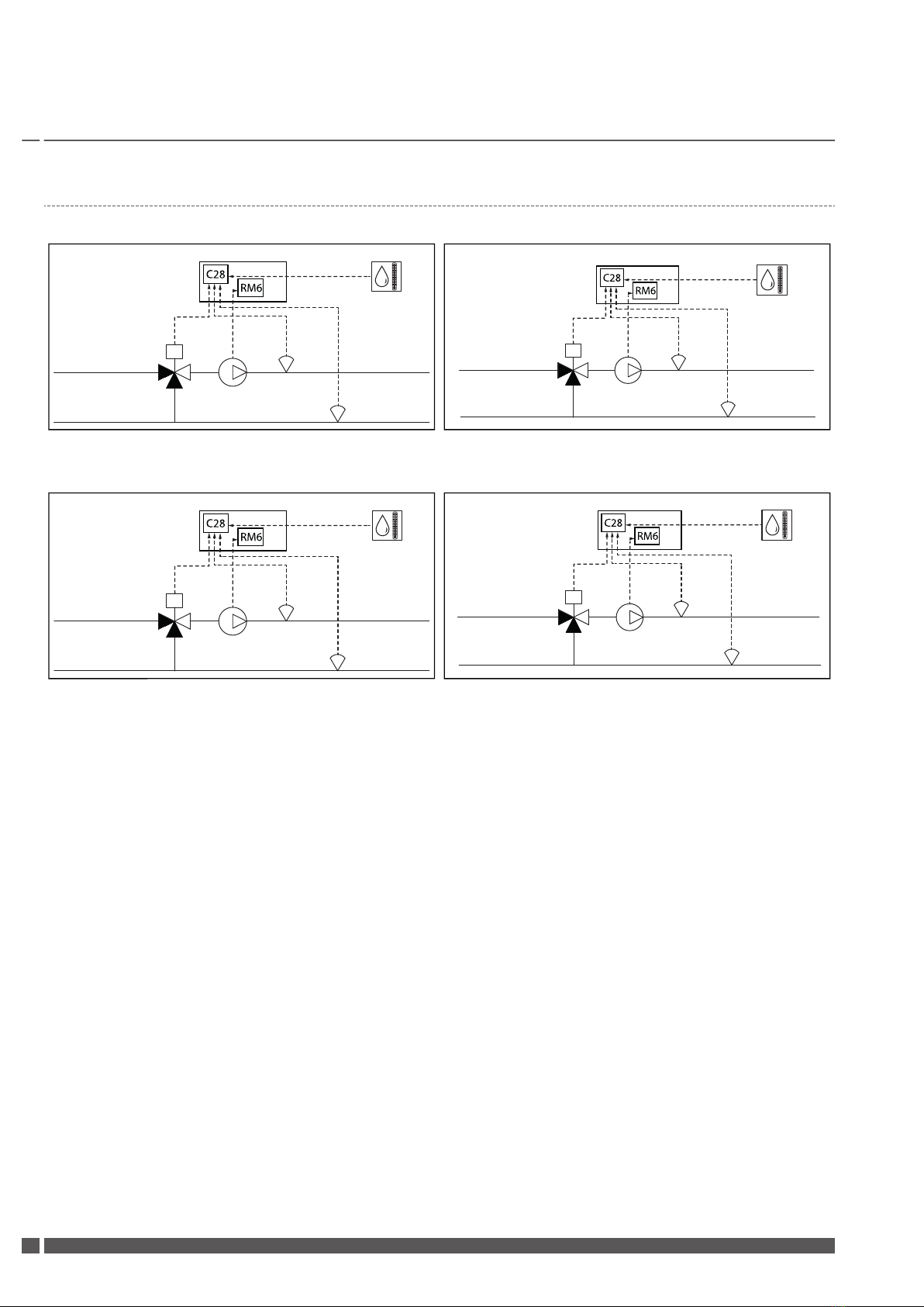
3.2 Distribution circuit 2-5
Distribution circuit 2 Distribution circuit 3
EM 1 C28: UI1 40,41
C28: UI2 40,42
RM6: 1DO 1715,
C28: AI1 30,31
C28: AI2 30,32
C28: AO1 90,91
EM 1
C28: UI3 43,44
C28: UI4 43,45
C28: AI3 33,34
RM6:DO2 18,20 C28: AI4 33,35
C28: AO2 90,92
Distribution circuit 4 Distribution circuit 5
EM 1
C28: UI1 40,41
C28: UI2 40,42
C28: AI1 30,31
RM6:DO1 15,17 C28: AI2 30,32
C28: AO1 90,91
EM 1
C28: UI3 43,44
C28: UI4 43,45
C28: AI3 33,34
RM6: DO2 18,20 C28: AI4 33,35
C28: AO2 90,92
Installation Guide Expansion module 1
VQILV502 Thermia Värmepumpar
10

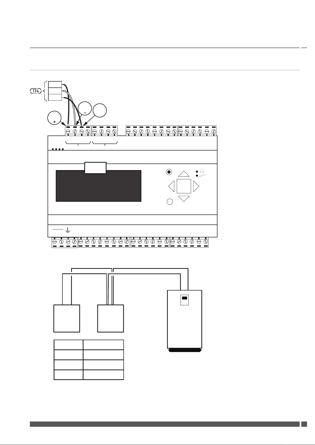
Connection example: Distribution circuit 2
C28: UI1 40,41
C28: UI2 40,42
RM6: 1DO 1715,
C28: AI1 30,31
C28: AI2 30,32
C28: AO1
N
F
90,91
P1 RxTx
P/B
P2 RxTx
P
1
P
2
B 50
A 51
N 52
E 53
B 60
A 61
N 62
E 63
Dl1 71
Dl2 72
Dl3 73
Dl4 74
Dl5 75
Dl6 76
Dl7 77
Dl8 78
Agnd 90
AO1 91
AO2 92
AO3 93
AO4 94
AO5 95
1 G +
3
2 G0 -
4 +C
10 GDO
11 DO1
12 DO2
13 DO3
14 DO4
15 DO5
16 DO6
17 DO7
31 Al1
30 Agnd
32 Al2
34 Al3
35 Al4
33 Agnd
41 Ul1
40 Agnd
42 Ul2
44 Ul3
45 Ul4
43 Agnd
C
OK
Ext.
Disp.
15 NO
16 NC
17 DO1
18 NO
19 NC
20 DO2
21 NO
22 NC
23 DO3
24 NO
25 NC
26 DO4
27 NO
28 NC
29 DO5
30 NO
31 NC
32 DO6
DO1
C1/2
DO2
DO3
C3/4
DO4
DO5
C5/6
DO6
12
24V~13
24V~14
1
2
3
4
5
6
7
8
9
10
11
C28
RM6
15 NO
16 NC
17 DO1
1a
1b
1a. Potential free output for circulation pump
1b. External power supply for circulation pump
Installation Guide Expansion module 1
Thermia Värmepumpar VQILV502 11
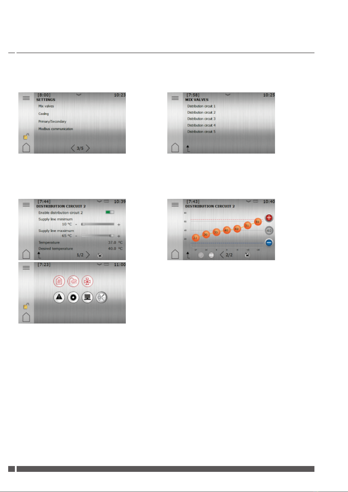
For this example, to access and activate Distribution circuit 2, you first need to enter the access code as described in the Commissioning
Guide. Then navigate to "Mix valves" in Settings and press the text "Distribution circuit 2".
On page 1, set the values for minimum/maximum supply line temperature. On page 2, you can adjust the heat curve for Distribution
circuit 2. Notice that, depending on if the distribution circuit is set as a radiator or floor heating system, the "Factory reset" button will set
different values. After all the adjustments are made, go back to page 1 and press the switch at the top of the page to activate the func-
tion and also make it visible and accessible in the menu for the end user.
Installation Guide Expansion module 1
VQILV502 Thermia Värmepumpar
12
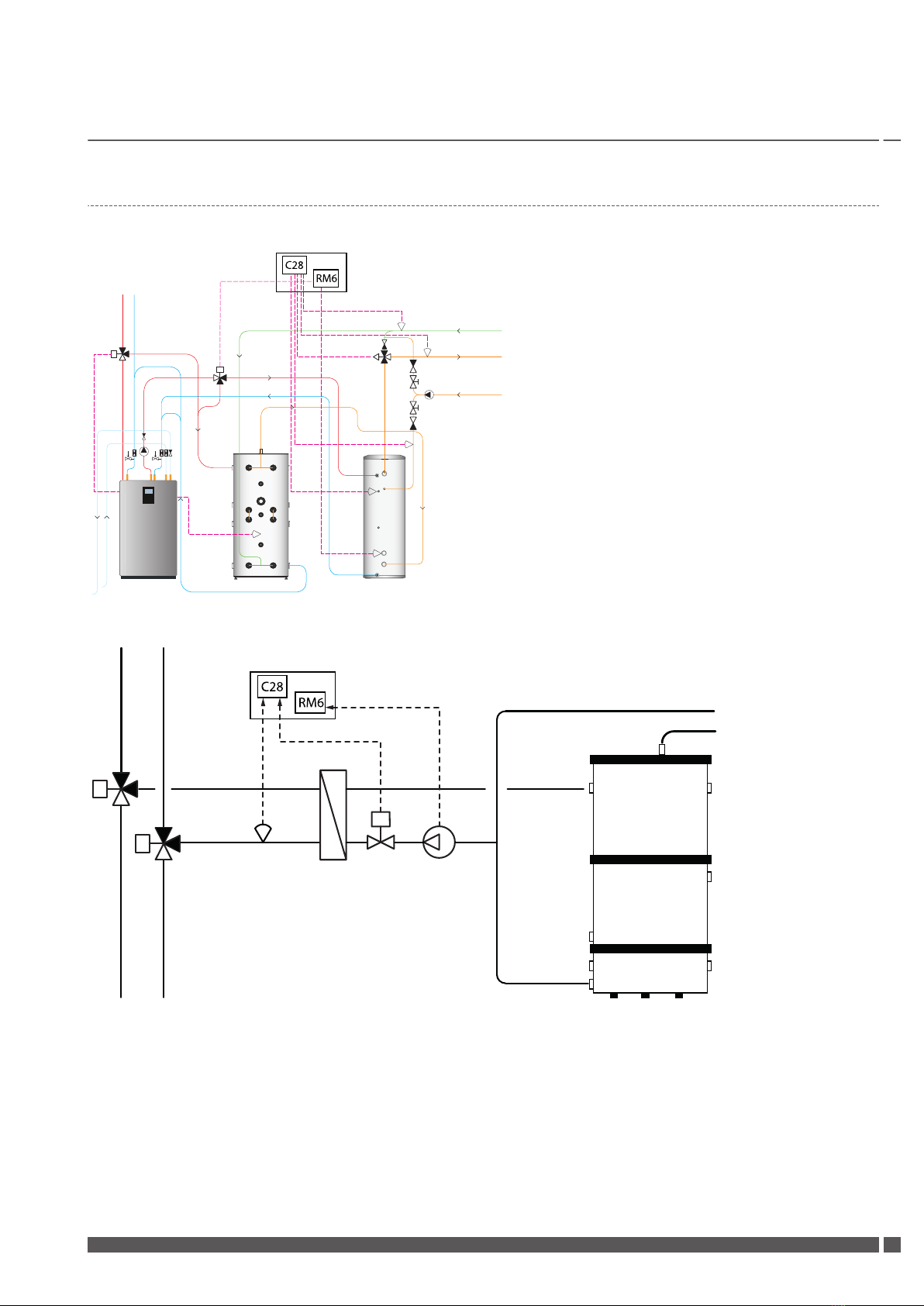
3.3 TWC/WCS
TWC
EM 1TWC
RM6: D04
24,26 C28: AI3 33,34
C28: AI1 30,31
C28: AI2 30,32
C28: AO1
90,Y91
C28: AI1
33,35
RM6: D03
21,23
WCS
C28: UI2
C28:
AO3
40,42
RM6:
DO5 27,29
90,Y:93
EM 1
Installation Guide Expansion module 1
Thermia Värmepumpar VQILV502 13

3.4 Cooling/Cooling2
EM 1
C28: UI3 43,Y:44
C28: UI4 43,Y:45
C28:
AI2
30,32
C28:
AI1
30,31
RM6:
DO1
15,17
C28:
AO1
90,Y:91
C28:
AI3
33,34
C28:
AI4
33,35
RM6:
DO2
18,20
RM6:
DO3
21,23
EM 1
C28:
AO2 90,Y:92
RM6:
DO5
27,29
C28:
UI2 40,42
C28:
UI1 40,41
RM6:
DO4
24,26
Installation Guide Expansion module 1
VQILV502 Thermia Värmepumpar
14
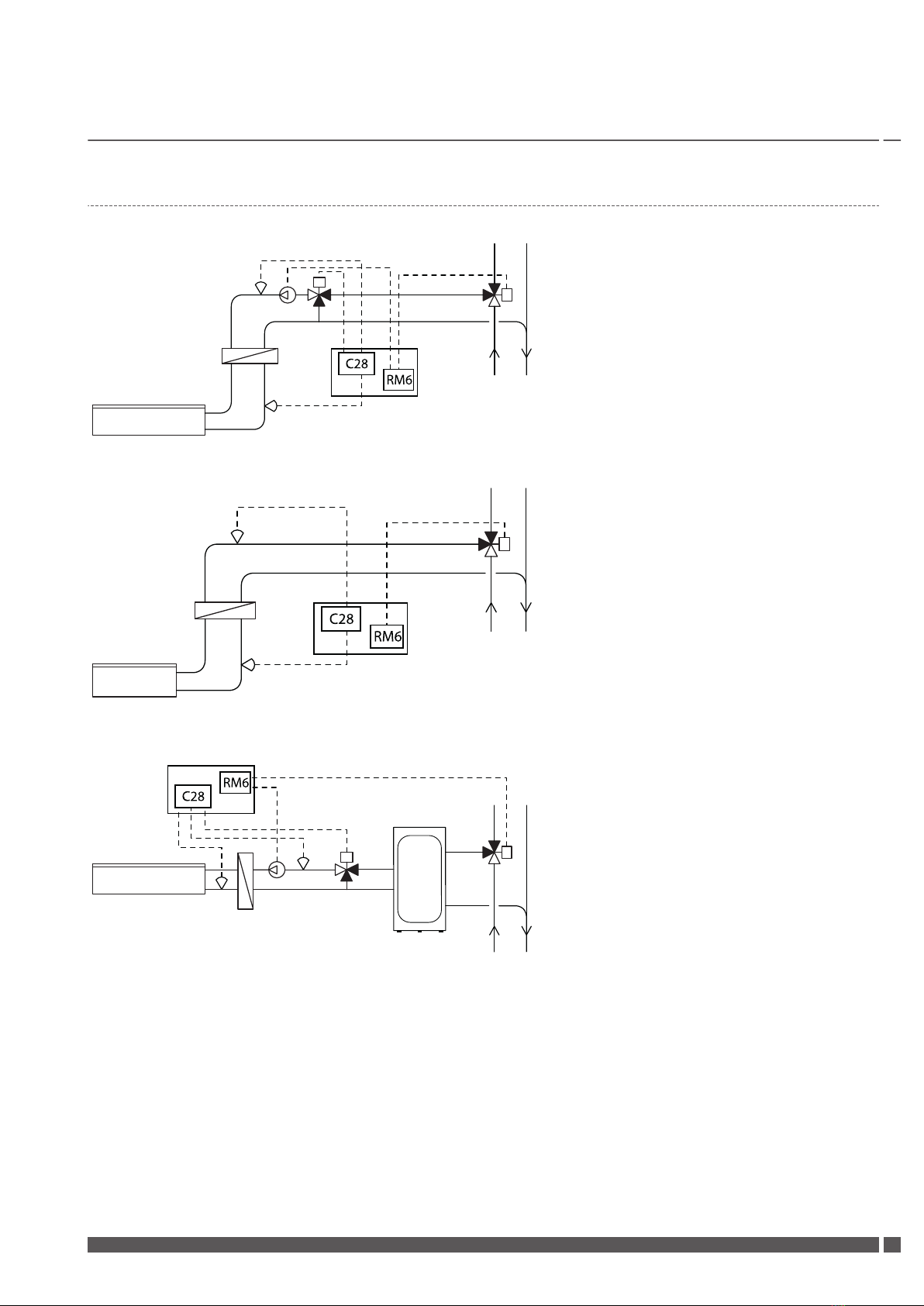
3.5 Pool
Alt. 1
C28:
AO1
90, Y:91
RM6: DO1 15, 17
C28: AI1 30, 31
C28: AI2 30, 32
RM6: DO3 21, 23
EM1
Alt. 2
RM6: DO3 21, 23
C28: AI1 30, 31
EM1
C28: AI2 30, 32
Alt. 3
C28: AO1
90, Y:91
RM6:
DO1
15, 17
C28:
AI1
30, 31
C28:
AI2
30, 32
RM6: DO3 21, 23
EM1
Installation Guide Expansion module 1
Thermia Värmepumpar VQILV502 15

Alt. 4 NB! This solution has to be set as two distribution circuits, this example shows Distribution circuit 2 and 3.
EM1
C28:
C28: AI1 30, 31
AI2
30, 32
RM6:
DO1
15, 17
C28: AO1
90, 91
C28: AI3
33, 34
RM6:
DO2
18, 20
C28: AI4
33, 35
C28: AO2
90, 92
Installation Guide Expansion module 1
VQILV502 Thermia Värmepumpar
16
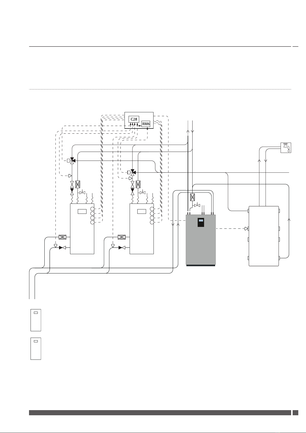
3.6 Legacy
Activation and settings for Primary/Secondary, Genesis and Legacy
EM 1
C28:
AI3
33,34
RM6:
DO4
24,26
RM6:
DO3
21,23
C28:
AI4
33,35
C28:
AI2
30,32
C28:
AI1
30,31
1
2
3
4
1
2
3
4
12
1
1. Start signal (RM6: DO1 15, 17)
2. Signal compressor in operation (C28: DI1 71, 4 +C)
3. Alarm (C28: DI2 72, 4 +C)
4. Operating pressure switch (C28: DI5 75, 4 +C)
2
1. Start signal (RM6: DO2 18, 20)
2. Signal compressor in operation (C28: DI3 73, 4 +C)
3. Alarm (C28: DI4 74, 4 +C)
4. Operating pressure switch (C28: DI7 77, 4 +C)
Installation Guide Expansion module 1
Thermia Värmepumpar VQILV502 17
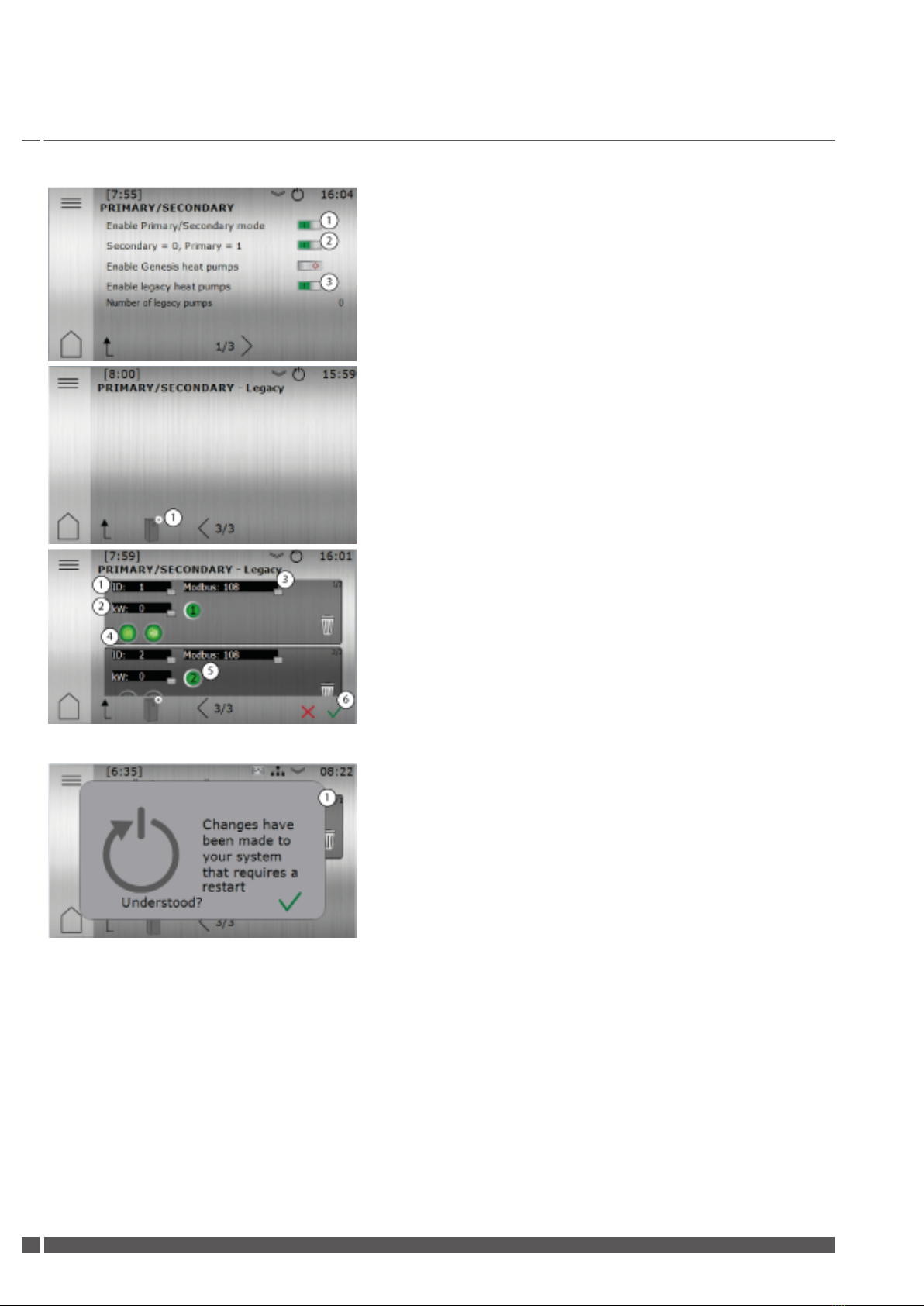
1. Activate if the heat pump should be active in a primary /secondary installa-
tion. In a single installation no activation needs to be made in this menu.
2. Activate primary heat pump.
3. Activate if the secondary heat pump is a legacy heat pump.
1. Press the following Icon to add new legacy heat pumps to the system.
1. Fill in heat pump ID for Legacy heat pump (Legacy no1=ID 1, Legacy no 2=
ID 2, etc.).
2. Type the Legacy heat pumps kW capacity.
3. Every EM1 module supports 2 legacy heat pumps. Therefor set Modbus to
108 for Legacy 1 and 2 (ID 1 and 2) and Modbus 109 for Legacy 3 and 4, etc.
4. Choose whether the Legacy heat pump should be active for heat or hot
water or both.
5. Internal ID for EM1 connection. The number indicates which internal ID the
legacy heat pump will have when it communicates with EM1 (The numbers
have to be either 1 OR 2 within the same Modbus address).
6. Confirmation is needed when changes have been made, and will also need
a restart to take effect.
1. A pop-up with a restart icon is shown in the display whenever a restart is
needed. This pop-up is merely information.
To activate restart, navigate to the menu “Operating mode”, set the heat pump to mode “Off” and press the restart symbol which will
appear.
Installation Guide Expansion module 1
VQILV502 Thermia Värmepumpar
18

1. When this symbol is shown in the top bar, changes have been made that
requires a restart.
2. Restart button (Requires that you´re logged in).
N
There might be several changes that will need a restart to function.
The pop-up information can appear in more than one occasion during
a configuration, so when the final configuration is done, only one re-
start is necessary.
Installation Guide Expansion module 1
Thermia Värmepumpar VQILV502 19

4 Configuring the module
4.1 Language selection
Navigate to Installation in the menu and press right arrow to enter the installation menu.
Manual test
Installation
OKOK
>
OK
c
Press OK and change language setting with up/down arrows, confirm with OK, exit by pressing repeatedly on the left arrow until you
reach the start menu.
Installation
Language:
English OKOKOK
c
Installation Guide Expansion module 1
VQILV502 Thermia Värmepumpar
20
Table of contents
Other Thermia Boiler Supplies manuals


