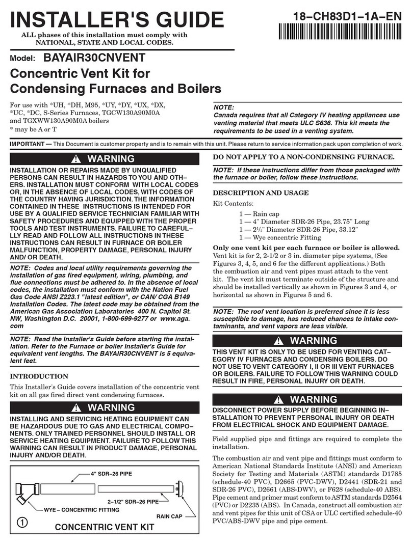
4.8.2 Feed system - Screw 2 on LB 62
4.8.3 Feed system - Rotary agitator 63
4.8.4 Discharge - Cyclone 1 (feed system-
configuration 8)
64
4.8.5 Feed system - Cyclone 1 / 2 (suction
screw)
65
4.8.6 Feed system - Cyclone 1 / 2 (4/8 probe
switch)
66
4.9 Network pump 68
4.9.1 Network pump - Status 68
4.9.2 Network pump - Temperatures 69
4.9.3 Network pump - Service 70
4.10 Cascade 72
4.10.1 Cascade - Status 72
4.10.2 Cascade - Backup boiler 72
4.10.3 Cascade - Temperatures 73
4.10.4 Cascade - Service 74
4.11 Difference regulator 75
4.11.1 Difference regulator - Status 75
4.11.2 Difference regulator - Temperatures 75
4.11.3 Difference regulator - Times 76
4.11.4 Difference regulator - Service 76
4.12 Circulation pump 77
4.12.1 Circulation pump - Status 77
4.12.2 Circulation pump - Temperatures 77
4.12.3 Circulation pump - Times 78
4.12.4 Circulation pump - Service 78
4.13 Manual 79
4.13.1 Manual - Manual operation 79
4.13.2 Manual - Digital outputs 80
4.13.3 Manual - Analogue outputs 80
4.13.4 Manual - Digital inputs 81
4.14 System 82
4.14.1 System - Settings 82
Setting - Boiler temperature
82
Setting - Slide-on duct
83
Setting - Flue gas
84
Setting - Ignition
92
Setting - Air settings
93
Setting - Fuel slide-in
95
Setting - Vibration / WOS / Cleaning
98
Setting - WOS / Cleaning
99
Set - Cleaning
100
Setting - Combustion chamber
101
Setting - Lambda values
103
Set - Lambda probe
104
Setting - General settings
106
4.14.2 System - Current values 108
Operation hours
108
4.14.3 System - Sensors and pumps 109
4.14.4 System - System selection 109
4.15 Diagnostics 110
4.15.1 Diagnosis – Current fault list 110
4.15.2 Diagnosis – Clear pending error 110
4.15.3 Diagnostics - Error history 110
4.15.4 Diagnostics - Clear error history 110
4.16 Touchscreen 111
4.16.1 Touchscreen - Display settings 111
Display settings - General
111
Display settings - Basic display
112
Display settings - Date / Time
112
Display settings - Software update / Service
112
4.16.2 Touchscreen - Display operating rights 113
Froling Connect
114
4.16.3 Touchscreen - Display allocation 114
5 FAQ 115
5.1 Calibrate the broadband probe 115
5.2 PDM / 0 - 10V settings 116
5.3 Boiler operating statuses 117
5.4 Boiler modes 118
5.4.1 "Automatic” mode without storage tank 118
5.4.2 “Automatic” mode with storage tank 119
5.4.3 “Continuous load” mode without storage
tank
120
5.4.4 “Continuous load” mode with storage
tank
120
5.4.5 “Domestic hot water” mode without
storage tank
120
5.4.6 “Domestic hot water” mode with storage
tank
122
5.5 Setting times 123
5.6 Calibrating the touchscreen 125
5.7 Software update Lambdatronic 3200 127
5.7.1 Carrying out a software update on the
boiler controller
128
5.7.2 Carrying out a software update on the
touch control
130
5.7.3 Finishing a software update 131
6 Notes 132
7 Appendix 134
7.1 Addresses 134
7.1.1 Address of manufacturer 134
Customer service
134
7.1.2 Address of the installer 134
Table of contents
Service manual Lambdatronic H 3200 for wood chip boiler | B1480519_en 3
