3
!Please note
Electronic assemblies can be
damaged by electrostatic dis-
charge.
Prior to commencing any work,
touch earthed objects such as
heating or water pipes to dis-
charge static loads.
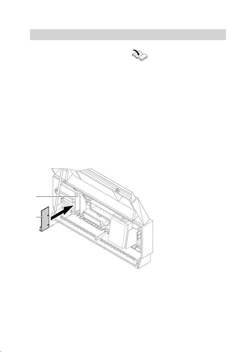
For opening the control units
and position A in the following
diagrams, see the correspond-
ing installation and service
instructions.
Vitotronic 100, 200, 300, 300-K, 333, 050, 200-H
■ Vitotronic 100, type GC1, GC1B,
GC4, GC4B, GC7B
■ Vitotronic 200, type GW1, GW1B,
GW4B
■ Vitotronic 050 and 200-H, type
HK1W, HK3W
■ Vitotronic 300, type GW2, GW2B,
GW4, GW4B
■ Vitotronic 300-K, type MW2, MW2B
■ Vitotronic 333, type MW2
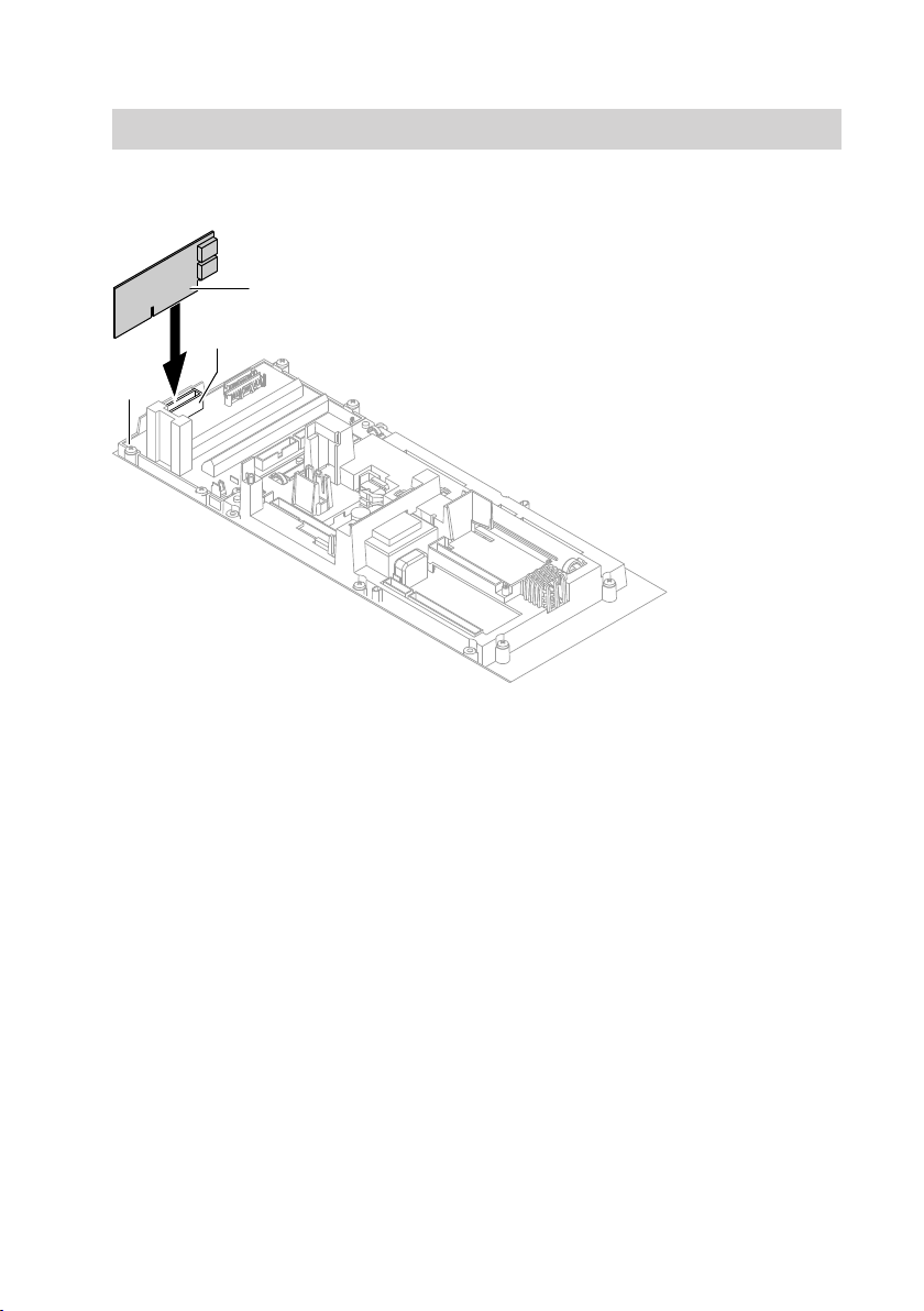
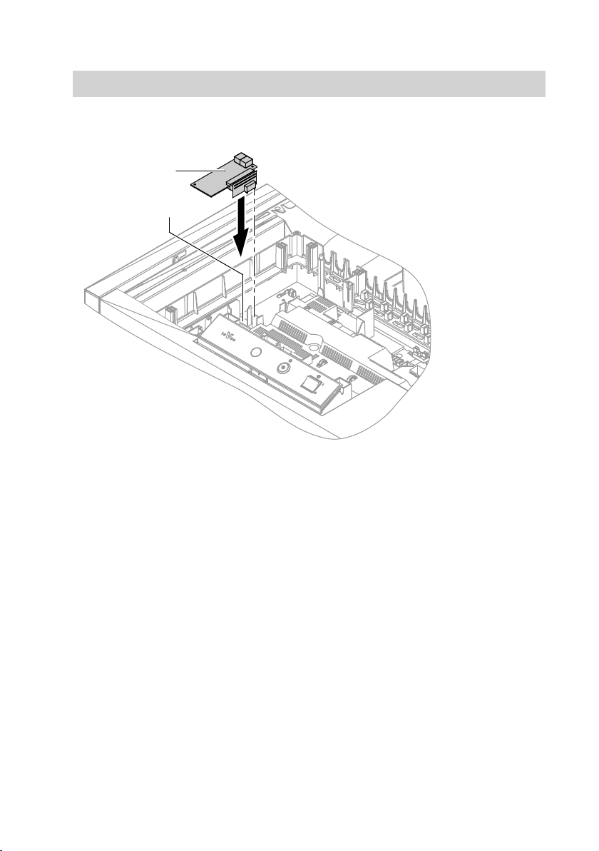
AMain control unit PCB BLON communication module
Vitotronic 100, 200, 300, type C...
■ Vitotronic 100, type CC1E
■ Vitotronic 200, type CO1E
■ Vitotronic 300, type CM1E
Installation
5780 510 GB