thermital SOL 300 User manual

1
ENGLISH
THERMITAL MODEX SOL 300
The SOL 300 is a separation module incorporating a plate heat exchanger used in systems where energy is supplied to
two hot water buffer storage cylinders – or at two different heights to a single buffer cylinder – by a solar heating system
equipped with arrays of collectors. The electronic control system governs the revolutions (0-10 V speed control function)
of the high efficiency pumps on the primary and secondary circuits so as to ensure optimum exploitation and manage-
ment of the energy produced. The controller is also designed to allow remote control of the system by way of an Ethernet
port, save system-related operating data to an SD card, and report any irregular or abnormal events that may occur.
The primary circuit is equipped with an electronic flow meter (Vortex flow sensor) displaying the flow rate and allowing
computation of the amount of heat exchanged.
Description Qty
1 Solar module with packing 1
2 Instruction manual 1
DESCRIPTION
CONTENTS OF THE KIT
GENERAL SAFETY INFORMATION AND PRECAUTIONS
READ THIS MANUAL WITH CARE BEFORE COMMENCING ANY OPERATION ON THE PRODUCT.
The manufacturer reserves the right to make changes to the product at any time and without notice, in the interests of re-
flecting technological progress and responding to specific production, installation and positioning requirements. Accor-
dingly, whilst the illustrations published in this manual may differ slightly from the product in your possession, all aspects
of safety and information regarding the product remain guaranteed.
This manual is an integral part of the product and should be kept in such way as to ensure that it stays intact and can
continue to be consulted throughout the service life of the module.
It should always accompany the product and be preserved with care to enable further consultation, even in the event that
the module may be sold or transferred to another owner, or left in place when moving away from the property where it is
installed, so as to remain available to the new owner of the property or to service technicians.
cod. Doc-0072228 - Rev. 5 (05/17)

2
GENERAL SAFETY INFORMATION
INSTALLATION
Before commencing any work on the product, make certain it is isolated from the mains power supply.
The product must be installed in conformity with the laws and standards applicable in the country of installation. The liability
of the manufacturer is limited to the supply of the product. The product must be installed adopting best professional prac-
tices, by suitably qualified persons working for a company that will assume full responsibility for the completed installation.
The manufacturer cannot be held responsible for consequences deriving from the unauthorised modification of the product
or from the use of non-original spare parts.
b Do not expose the product to the elements. It is not designed for use outdoors
ELECTRICAL CONNECTIONS
The system and/or the controller must be installed and connected by persons qualified under current statutory regulations.
Where an electronic controller is installed, connect the power cable of the device to a two pole switch complete with fuses
(power supply 230Vac 50Hz). It is indispensable that the system be properly connected to earth.
b
The control unit must be connected on the upstream side to the mains supply by way of a main differential switch in
accordance with current regulations. The correct operation of the control unit is guaranteed only when used in con-
junction with the motor for which it was designed and built. The manufacturer acknowledges no liability for improper
use of the control unit.
WATER CONNECTIONS
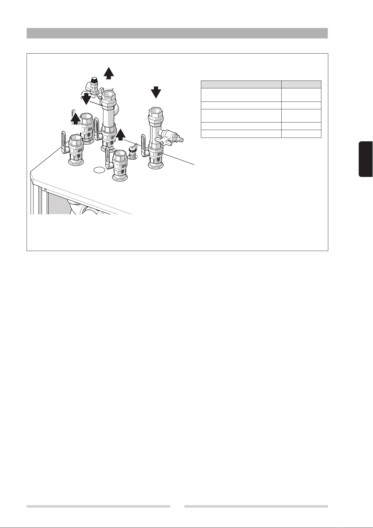
Having transported/handled the module into position, proceed to tighten all the ring nuts of the various pipe fittings. Take
particular care when connecting the module to the water system: during the step of tightening the pipe that connects the
water supply, the torque applied to the ring nut must be counteracted by applying a second wrench to the fitting, so that the
pipes of the module will not be strained and damaged.
b
All installation, connection and testing operations must be entrusted to skilled professionals who can be relied upon to
observe current standards and follow the instructions given in the accompanying manual. N.B. All pipelines must be
insulated in accordance with statutory regulations.
In any event, it is fundamentally important to observe certain general rules when using the product:
- Do not touch hot parts of the equipment, such as water inlet and outlet pipelines. Any contact with these parts could result
in serious scalding.
- Do not splash the module with water and other liquids.
- Do not stand or place any extraneous object on the module.
- Do not expose the module to steam rising from a cooker or hob.
- Do not allow children and inexpert persons to use the module.
- Do not touch the module with wet or damp body parts and/or bare feet.
- Do not tug or pull electrical cables.
- Put on protective gloves and safety footwear before handling the product.
PRE-INSTALLATION WARNINGS AND INDICATIONS
- When electrical power failures occur, the motorised valves are liable to lock up in the open position, causing the SOL 300
to overheat
- Any work required on electrical connections must be entrusted to an expert service technician.
- Water circulating inside the SOL 300 module may be very hot and highly pressurised. Before the module is disassembled
for whatever reason, the system should be drained of water, and the shut-off valves securely closed.
- Installation and all other work on the system must be carried out in compliance with local regulations.
- In the event of malfunctions occurring, whatever their nature, always contact your regular plumber. Carrying out repairs
without authorisation is forbidden, as unforeseen damage can occur
The manufacturer declines responsibility for any damage caused by inappropriate use of the product. The module must not
be connected directly to a heat generator.

3
ENGLISH
5
8
17
6
10
12
13
11
9
10
1
15
16
14
2
4
3
5
17
7
8
STRUTTURA
1 Solar circuit pump
2 Motorised 3-way ball valve F-F-F 1”1/2
3 Vortex Flow Sensor flow rate/temperature gauge 200 l/min 1”1/4
4 Bleed pipe with manual vent valve
5 Solar circuit ball valves, sandblasted brass, F-F 1”1/2
6 Motorised two way bypass valve, primary circuit, M-M 1”
7 Safety valve kit 10 bar
8 Solar circuit filling/drain cock
9 Motorised two-way ball valve, primary circuit return, F-F-F 1”1/2
10 Non-return valve, sandblasted brass, F-F 1”1/2
11 Stainless steel plate heat exchanger
12 Power board with thermal magnetic breaker
13 XTDC electronic controller
14 Pressure-temperature gauge, RPS, 1 - 8 bar
15 Heating circuit pump
16 Filling/drain cock
17 Heating circuit ball valves, sandblasted brass, F-F 1”1/2
SYSTEM LAYOUT

4
WATER CIRCUIT
1
2
2
11
7
89
9
9
9
9
9
10
10
11
1
1
3
4
4
5
S5
9
6
1 Two way valve
2 Modulating pump
3 Three way diverter valve
4 Non-return valve
5 Cock with cap
6 Bleed pipe with manual vent valve
7 Flow meter with temperature gauge
8 Solar circuit safety valve
9 Drain valve
10 Two way valve
11 Pressure transducer
12
2
11
7
89
9
S5
9
9
9
9
6
9
10
10
11
1
Puffer 1
Puffer 2
1
3
4
4
5

5
ENGLISH
TECHNICAL SPECIFICATIONS
DESCRIPTION SOL 300
Thermal power exchanged 129 kW
Maximum flow rate, primary circuit 6000 l/h
Maximum flow rate, secondary circuit 116,7 l/min
Primary circuit ΔT 20 °C
Surface area of panels 200 m2
Minimum permissible temperature 2 °C
Maximum operating temperature 110 °C
Maximum operating pressure, primary side 10 bar
Non-return valve opening pressure, primary circuit 40 mbar
Non-return valve opening pressure, secondary circuit 40 mbar
Absorbed electric power, primary circulator (max/stand-by) 155 / 1,72 W
Absorbed electric power, second circulator (max/stand-by) 70 / 1 W
Absorbed electric power, solar controller (stand-by) 0,5 W
Energy efficiency, solar controller 1 %
Power supply voltage 230 V
Power supply frequency 50-60 Hz
Ingress protection 40 IP
Net weight 155 kg
Water volume 45 l
Heating curves - pressure drop
9
10
11
12
8
7
6
5
4
2
3
1
0
88,2
98,0
107,8
117,6
78,4
68,6
58,8
49,0
39,2
19,6
29,4
9,8
0
0 1000 2000 3000 4000 5000 6000
∆P (m H2O)
∆P (kPa)
Produzione ACS (l/h)
Wilo Stratos Para 30/1-12
Wilo Stratos Para 30/1-8
DP Primario
DP Secondario
DHW production (l/h)

6
Secondary circuit efficiency
Secondary pump efficiency (%)
35
25
45
55
65
75
85
105
95
115
125
01113161820
Dt secondario
Portata secondario (l/min
)
1
2
3
4
5
6
90
100
80
70
60
50
40
20
30
10
0
0
3000
2000 4000 5000 6000
Portata secondario (l/h)
Resa circolatore (%)
NB: Assuming primary circuit parameters 0.5 l/min*m2 - ΔT 12 °C (95 °C to 83 °C) / Secondary circuit flow 90 °C
1 200 m2solar (100 l/min)
2 180 m2solar (90 l/min)
3 160 m2solar (80 l/min)
4 140 m2solar (70 l/min)
5 120 m2solar (60 l/min)
6 100 m2solar (50 l/min)
Secondary ΔT
Secondary ow rate (l/min)
Pump efficiency (%)

7
ENGLISH
DIMENSIONS AND FITTINGS
MP
RP
RS
MS2
MS1
SOL 300
RP Primary (solar) circuit
return 1 1/2” F
MP Primary (solar) circuit flow 1 1/2” F
RS Recirculation, secondary
circuit 1 1/2” F
MS1 Secondary circuit flow 1 1 1/2” F
MS2 Secondary circuit flow 2 1 1/2” F
Dimensions:
Height 1140 mm
Width 1000 mm
Depth 500 mm
It is recommended that a clearance of at least
50 cm should be maintained on all sides of the
module, in order to facilitate inspection and ser-
vicing operations.

8
WIRING DIAGRAM
NF
230 V
esc
MICR O
SD
(**)
RC VFS2 VFS1
CANCAN
GND
S1
S2
S3
S4
S5
S6
S7
S8
V1
V2
PF-Relais
NC
C
NO
Relais
R6
R5
R4
R3
R2
R1
N
L
Netz/Mains
VFS 10-200 l/min
RPS 10 bar
C1
RSR-XRSR-OPRSR-OP
BYPASS PRIM. 1"1/2DEV. 3 VIE
6 A
(*)
C2
N
N
230VAC
max. 12V
LAN
S1 Storage sensor, high
S2 Storage sensor, low
S5 Heat exchanger sensor
S8 Solar collector sensor
V1 Speed control, pump 1
V2 Speed control, pump 2
C1 Primary circuit pump
C2 Secondary circuit pump
(*) Secured to frame
(**) Slot accepting SD Card for Data logging and firmware updates. Make certain the SD card is fitted the right
way round! The card must be inserted without forcing!

9
ENGLISH
SYSTEM LAYOUT
CONTROL PANEL
b Before working on the controller, disconnect the power supply and ensure it cannot be reconnected! Check that
there is no power! Electrical connections must be made only by an expert service technician, and in accordance
with pertinent regulations and standards.
- Do not use the controller if there are visible signs of damage on the housing.
- Low voltage cables must be routed separately from mains voltage cables. Feed temperature sensor cables only into
the left hand side of the controller, and mains voltage cables only into the right hand side.
- The user must install a device capable of disconnecting all poles, such as a thermal magnetic breaker.
- Cables connected to the controller must be stripped by no more than 55 mm, and the cable jacket must extend into the
housing to a point just beyond the strain relief gland.
- The controller and the Vortex Flow Sensor must have the same ground potential. The VFS has a functional earth connec-
tion (PELV). The PE output of the controller must be connected to the pipe system at a point near the sensor.
Mandata
secondario 1
Ritorno
primario
Mandata
primario
Ritorno
secondario
Mandata
secondario 2
Secondary
circuit ow 1
Secondary
circuit ow 2
Primary circuit
ow
Secondary
circuit
return
Primary circuit
return

10
INSTALLATION
HANDLING
The responsibilities of the user include providing the equipment needed to handle and unload the module, checking the
number of items delivered, and verifying the integrity of the material.
The module is positioned on a pallet; use only a transpallet truck for handling purposes and fix the pallet securely, bearing
in mind that the module will be at risk of tipping over if not restrained, given its weight and high centre of gravity.
Take care that the module is not exposed to impact, and remove packing materials only after it has been positioned.
PRELIMINARY CHECKS
Before commencing operations, remove the packing with care:
-remove the box covering the module;
-remove the nylon film;
-remove the protective wooden cage.
Check that the module is perfectly intact. If the product is found to be defective or damaged, do not install or attempt to
repair it, but contact the dealer immediately.
Dispose of discarded packaging materials in accordance with current statutory regulations.
b Ensure that safety valves are clearly visible and easily accessible.
b The drain line serving the safety valves must be designed and installed in compliance with current standards.
b The module must be positioned in close proximity to the storage cylinder. The system is sized assuming that the
length of the pipelines connecting the module and storage cylinder will be 4 metres (flow + return)
b Before commencing any work on the product, make certain it is isolated from the mains power supply.
b The product must be installed in conformity with the laws and standards applicable in the country of installation.
b The liability of the manufacturer is limited to the supply of the product. The product must be installed adopting best
professional practices by suitably qualified persons working for a company that will assume full responsibility for
the completed installation.
ASSEMBLY AND START-UP
Bear in mind the following before installing the product:
- The module is designed to heat potable water, operating in conjunction with a storage cylinder. Any use deviating from
or unrelated to the intended use is considered improper. Do not connect the module directly to the heat generator.
- The product is not designed to be operated by persons (including children) with limited physical, psychological, sen-
sorial or mental capabilities.
- In the event that the conduit for the cable connecting the module to the mains is damaged, it must be replaced only by
an expert service technician.
- The installation must comply with all applicable laws and standards.
b Installation and connection of the product must be performed by an authorised, specialist company. The company
installing the product assumes all responsibility for ensuring that the installation and functioning of the product
conform to applicable standards.
b The product must be stored in a dry place, protected from frost. The product must be installed where it is protected
against water splash. Ambient temperature in the place of installation must not exceed 40 °C during operation of
the product.
b It is advisable to install the product as near as practically possible to the storage cylinder, in order to avoid unne-
cessary heat loss from the connecting pipes. The product must be placed a surface that is flat and stable, as far as
possible, and levelled up by means of the adjustable feet provided.
b Be certain to adjust the feet of the module as appropriate, so as to avoid stresses.
WATER CONNECTIONS
Connections to the various pipes of the system are made as indicated on the stickers affixed to the module and in ac-
cordance with the layout diagram in this manual. The pipelines connecting with the storage cylinder must be as short as

11
ENGLISH
possible! The recommended pipe material is steel or copper. When assembling pipelines and fittings, always observe the
installation sequence indicated, so as to avoid electrochemical corrosion.
a The product must not be installed in natural circulation heating systems!
The collector circuit expansion vessel must be installed using a direct connection. The installation of isolating valves
(except for pressure regulators such as sealable closure valves) is not permitted! Tighten the fittings only when the pipeli-
nes are hermetically tight. In any event, be careful not to tighten or apply any forcing action to preassembled components
and couplings of the module! Check also that the collars of all screw-threaded flat seal fittings are secured at the correct
tightening torque, as these connections can work loose during transport.
ELECTRICAL CONNECTIONS
Electrical connections must be entrusted to persons qualified under current statutory regulations. Connect the power ca-
ble of the electronic controller to a two pole switch complete with fuses (power supply 230 Vac 50 Hz). It is indispensable
that the system be properly connected to earth.
b The control unit must be connected on the upstream side to the mains supply by way of a main differential switch in
accordance with current regulations. The manufacturer acknowledges no liability for improper use of the equipment.
b Electrical connections must be made by a qualified technician.
b Never under any circumstances dispose of the controller with ordinary household refuse. Dispose of the controller
only at designated collection points or return it to the dealer or manufacturer.
b The manufacturer declines all responsibility for damage caused by failing to ground the appliance adequately or by
failure to respect the wiring diagrams provided in this manual.
USE
The SOL 300 module has stand-alone control capability.
To ensure correct operation of the module, the following parameters must be observed for each of the components indi-
cated:
b Deviation from these specific values could result in the SOL 300 being damaged, and consequently invalidate the
manufacturer’s warranty.
COMPONENTS UNIT OF
MEASURE
MAX/MIN PERMISSIBLE VALUE FOR COPPER-BRA-
ZED HEAT EXCHANGERS
pH 7-9 (considering saturation index)
Saturation Index (ΔpH) -0.2<0<+0.2
Total hardness °Fr 15-30
Conductivity μS/cm 10…500
Filterable substances mg/l <30
Free chlorine mg/l <0.5
Hydrogen Sulphide mg/l <0.05
Ammonia mg/l <2
Hydrogen Carbonate mg/l <300
Hydrogen Carbonate/Sulphide mg/l >1.0
Sulphide mg/l <1
Nitrate mg/l <100
Nitrite mg/l <0.1
Sulphate mg/l <100
Manganese mg/l <0.1
Dissolved iron mg/l <0.2
Free aggressive Carbon Dioxide mg/l <20

12
START-UP
The system must be filled and started up by an authorised specialist company. Technicians overseeing the procedure
must test the operation and leak-tightness of the entire system, including factory-assembled components. The operation
of the safety valve must be tested at regular intervals. It is recommended that the system be serviced annually by a spe-
cialist company.
When filling/draining the system, the ball valves on the inlets and outlets of the module should be opened slowly to avoid
pressure surges. When filling the collector circuit, use only the fill/drain fittings provided for this particular purpose.
Having completed the filling operation, close the collector return line and set the system pressure to 3 bar approx (the
level specified for expansion vessels with a pressure rating of 2.5 bar; the static height of the system must also be taken
into account).
b Make certain that mains power is safely disconnected before opening the cover of the controller! Do not fill the
system in strong sunlight as this could trigger vapour explosions!
FILLING PROCEDURE
Filling and flushing must continue until it is certain that the system has been completely purged of air! If flow noises are
audible during operation of the collector pump, this indicates that there is residual air in the system, which must be bled
out manually by operating the relative vent valve.
b Before commencing the fill and flush procedure, read the following directions carefully.
Storage side:
- First open the storage buffer line slowly, then the two storage return lines.
- Select manual operating mode at the controller and activate the pump (see parameter 3.2)
- Open the manual vent valves
- Allow the liquid to circulate for two minutes
- Open the diverter valve to direct flow to the storage cylinder.
- Continue recirculation until the liquid in the system is entirely free of bubbles
- Close the vent valves
- Set the controller for operation in automatic mode (see parameter 3.1).
Solar side:
- Use the filling/drain cocks to fill the system
- Select manual operating mode at the controller and activate the pump (see controller parameter 3.2)
- Open the vent valves
- Proceed with the filling operation until the liquid in the system is entirely free of bubbles
- Close the vent valves
- Set the controller for operation in automatic mode (see parameter 3.1).
USE AND FUNCTIONS OF THE CONTROLLER
DECLARATION OF CONFORMITY
Applying the CE mark to the controller, the manufacturer guarantees that the XTDC is in conformity with the following
directives:
- Low Voltage Directive 73/23/EEC, as amended by 93/68/EEC
- Electromagnetic Compatibility Directive 89/336/EEC version 92/31/EEC, version 93/68/EEC
The conformity of the product has been tested and the pertinent documentation and CE declaration of conformity are in
the possession of the manufacturer.
GENERAL INSTRUCTIONS
This technical documentation and the accompanying installation and operating instructions contain basic information
and important indications regarding safety, installation, setting, maintenance and optimum use of the controller. Accor-
dingly, the following instructions must be read and understood in their entirety by the specialist installer/technician and by
the user of the system before installing, starting up and operating the controller. All current safety standards, local power
utility directives and pertinent statutory regulations must be observed, likewise the installation and operating instructions
accompanying system components. The controller can under no circumstances serve as a substitute for any safety com-
ponent that the user is obligated to install!

13
ENGLISH
The assembly, electrical connection, start-up and maintenance of the product must be entrusted exclusively to expert
service technicians
Always keep these instructions in the vicinity of the controller.
CHANGES TO THE CONTROLLER
If changes are made to the controller, the safety and functionality both of the controller and of the entire system may be
adversely affected.
- Changes, additions to or conversion of the unit are forbidden unless written permission is obtained from the manufac-
turer.
- It is also forbidden to install additional components that have not been tested in conjunction with the controller.
- If safe operation of the controller cannot be guaranteed, for example by reason of damage to any component part, then
switch it off immediately and have it repaired/replaced.
- Any component or accessory of the controller that is not in perfect condition must be replaced immediately.
- Use only original parts and accessories supplied by the manufacturer.
- The manufacturer’s name plate and other factory marks applied to the controller must not be altered, removed or made
illegible.
- Only the settings described in these instructions are able to guarantee the correct operation of the controller.
WARRANTY AND LIABILITY
The controller has been developed and tested giving particular care to matters of quality and safety.
This said, warranty and liability shall not cover any injury or damage to persons or property that may be attributable to
one or more of the following causes:
- Failure to observe these installation and operating instructions.
- Improper installation, setting, start-up, maintenance and operation.
- Unsuitable repairs.
- Unauthorised structural changes to the product.
- Installation of additional components that have not been tested in conjunction with the controller.
- Any damage resulting from continued use of the controller even after an obvious defect has been discovered.
- Failure to use original replacement parts and accessories.
- Use of the product for any purpose other than its intended purpose.
- Operation above or below the limit values listed in the specifications.
- Force majeure.
DESCRIPTION OF THE CONTROLLER
About the controller
The XTDC Temperature Difference Controller enables efficient use and operational control of a solar or heating system. The
controller stands out above all for its practicality and the simplicity of its operation, which is virtually self-explanatory. Each
input produced by pressing one of the keys is assigned a specific function and an accompanying explanation. The items
of the controller menu include measurement values and settings, help messages and graphs, all of which easy to read and
understand.
Main features of the XTDC:
- Backlit display showing text and graphic content
- Simple viewing of current measurement values
- Analysis and monitoring of the system by means of statistical graphs, etc.
- Individual configuration of special functions
- Extensive setting menus with explanations
- Menu lock: activated to prevent unintentional alteration of settings
- Function allowing restoration of previously selected values or factory settings
- Wide range of additional functions.
Disposal
The controller conforms to the European RoHS directive 2002/95/EC regarding restrictions on the use of certain hazar-
dous substances in electrical and electronic equipment.
b Never under any circumstances dispose of the controller with ordinary household refuse. Dispose of the controller
only at designated collection points or return it to the dealer or manufacturer.

14
TECHNICAL SPECIFICATIONS
Electrical specications:
Voltage ............................................100 - 240VAC
Frequency .........................................50 - 60Hz
Power consumption ..................................0,5 - 3 W
Contact capacity:
Entire switched power for electronic relays.................460VA for AC1 / 240W for AC3
Electronic relay R1 ...................................min 5W…max 120W for AC3
Electronic relay R2 ...................................min.5W…max.120W for AC3
Entire switched power for mechanical relays ...............460VA for AC1 / 185W for AC3
Mechanical rela R3 ...................................460VA for AC1 / 460W for AC3
Mechanical rela R4 ...................................460VA for AC1 / 460W for AC3
Mechanical rela R5 ...................................460VA for AC1 / 460W for AC3
Mechanical rela R6 ...................................460VA for AC1 / 460W for AC3
Voltage-free relay R7 ..................................460VA for AC1 / 185W for AC3
0..10V output ........................................for working resistance 10Ω
PWM output.........................................Frequency 1kHz, level 10 V
Internal fuse.........................................3 x T2A / 250V slow blow
Ingress protection ...................................IP40
Protection class .....................................II
Sensor inputs........................................
8 x Pt1000 temp. sensor, 2 x Grundfos Direct Sensor, 1 x RC21/RC22
Measuring range
- PT1000 ...........................................-40°C to 300°C
- Grundfos direct sensor: ..............................0 °C to 100 °C (-25 °C/120 °C short term)
VFS
1 l/min - 12 l/min (VFS1-12) ............................RPS 0-0,6 bar
2 l/min - 40 l/min (VFS2-40) ............................0-1 bar
5 l/min - 100 l/min (VFS5-100) ..........................0-1,6 bar
10 l/min - 200 l/min (VFS10-200) ........................0-2,5 bar
. . . . . . . . . . . . . . . . . . . . . . . . . . . . . . . . . . . . . . . . . . . . . . . . . . . 0-4 bar
. . . . . . . . . . . . . . . . . . . . . . . . . . . . . . . . . . . . . . . . . . . . . . . . . . . 0-6 bar
. . . . . . . . . . . . . . . . . . . . . . . . . . . . . . . . . . . . . . . . . . . . . . . . . . . 0-10 bar
Network connections ................................Ethernet (optional)
. . . . . . . . . . . . . . . . . . . . . . . . . . . . . . . . . . . . . . . . . . . . . . . . . . . CAN Bus
Memory devices ....................................Slot for Micro SD cards
Clock..............................................Real Time Clock (RTC) with 24 hour battery backup
Permissible ambient conditions:
Ambient temperature:
- for controller operation ...............................0°C...40°C
- for transport/storage .................................0°C...60°C
Air humidity
for controller operation ................................max 85% relative humidity at 25°C
for transport/storage ..................................no moisture condensation permitted
Other specications and dimensions
Housing ............................................3-part, ABS plastic
Installation methods ..................................Wall-mounting, option of panel-mounting
Overall dimensions ...................................228 x 180 x 53 mm
Display.............................................Full graphic display, 128 x 128 pixels
Light diode .........................................2, one red, one green
Programming........................................4 keys
Temperature–resistance table for Pt1000 sensors
°C 0 10 20 30 40 50 60 70 80 90 100
Ω1000 1039 1077 1116 1155 1194 1232 1270 1308 1347 1385

15
ENGLISH
ELECTRICAL CONNECTIONS
- Before working on the controller, disconnect the power supply and ensure it cannot be reconnected! Check that there
is no power!
- Electrical connections must be made only by an expert service technician, and in accordance with pertinent regula-
tions and standards. Do not use the controller if there are visible signs of damage on the housing.
- Low voltage cables must be routed separately from mains voltage cables. Feed temperature sensor cables only into
the left hand side of the controller, and mains voltage cables only into the right hand side.
- The user must install a device capable of disconnecting all poles, such as a thermal magnetic breaker.
- Cables connected to the controller must be stripped by no more than 55 mm, and the cable jacket must extend into the
housing to a point just beyond the strain relief gland.
- The controller and the Vortex Flow Sensor must have the same ground potential. The VFS has a functional earth connec-
tion (PELV). The PE output of the controller must be connected to the pipe system at a point near the sensor.
Connection terminals
V2 V1 S8 S7
VFS2 1SFVCR
SD Card
Ethernet
S6 S5 S4 S3 S2 S1 GND R6NC CNOR5R4R3R2R1N L
Low voltage Voltage-free
relay
Relay Mains
Low voltage
b max. 12VAC/DC
Term. Connection for
S1 Sensor 1
S2 Sensor 2
...
S8 Sensor 8
V1 optional variable speed control output for high effi-
ciency pumps
V2 optional variable speed control output for high effi-
ciency pumps
VFS1 Grundfos Direct Sensor
VFS2 Grundfos Direct Sensor
SD Card slot
for data logging and firmware updates.
b Make certain the SD card is fitted the right way
round! The card must be inserted without forcing!
Ethernet
for connection to Local Area Network (LAN)
Voltage-free relay
NO normally open
C common
NC normally closed
Relay
b Current 230Vac 50-60Hz
Term. Connection for
R1 Relay1
R2 Relay 2
...
R6 Relay 6
N neutral conductor N
L live conductor L

16
SYSTEM VARIANTS:
The following layout drawings are provided purely as a guideline to the various water systems possible, and in no way
intended as complete.
b Never replace the controller if there is no need.
b Certain specific applications may require the inclusion of additional system components for operational and/or
safety purposes, such as, for example, shut-off valves, non-return valves, temperature control devices, anti-scald
devices, etc., and these must therefore be provided.
The layouts that can be adopted in the case of the SOL 300 are number 17 and number 18, illustrated in the figures
below.
S1
S8
S5
S2
R1
R2R3
S1
S8
S5
S2
R1
R2
R3
Layout 17
S1 Storage
S2 Storage
S5 Heat exchanger
S8 Collector
V1 Optional selection for R1
V2 Optional selection for R2
R1 Solar circuit pump
R2 Secondary circuit pump
R3 Valve – Storage S1 / Storage S2 (ON = Buffer
Storage S2)
Layout 18
S1 Storage high
S2 Storage low
S5 Heat exchanger
S8 Collector
V1 Optional selection for R1
V2 Optional selection for R2
R1 Solar circuit pump
R2 Secondary circuit pump
R3 Valve – Storage high S1 / Storage low S2 (ON =
Buffer Storage low S2)
SETUP WIZARD
The first time the controller is switched on, once the lan-
guage and the clock are set, a prompt will appear asking
whether or not the setup wizard is required. The wizard
can be called up again at a later time if needed, from the
special functions menu. The wizard will guide the user
through the basic settings in the correct sequence, pro-
viding a brief description of each parameter displayed.
Pressing “esc” once, the screen returns to the previous
value, so that it is always possible to go back or make
changes. Pressing “esc“ repeatedly, the steps of the se-
lection procedure can be undone one by one, without
confirming the wizard input. Finally, accessing menu 3.2
and selecting “Manual” mode, the installer can test the
various outputs with the components connected, and ve-
rify whether or not the readings from the sensors are relia-
ble. Thereafter, automatic mode is activated.
Start now the setup wizard?
No Yes
Setup wizard

17
ENGLISH
esc
(1)
(2)
(3)
(4)
Meaning of symbols in the display:
Pump (revolves with pump in operation)
Valve (black indicates flow)
Collector
Storage
Pool
Heat exchanger
Buffer pause (see buffer time)
Warning / error message
New information available
Logging currently active
More symbols can be found under the heading
"Special functions"
DISPLAY AND INPUT
The display (1), with full text and graphics mode, is self-
explanatory to all intents and purposes, making the con-
troller easy to use.
To quit the settings menu, press “esc” (3).
The status LED (2) lights up green when a relay is active,
or blinks red when an error occurs.
Commands are entered using four keys (3) and (4), which
are assigned context-sensitive functions.
The “esc“ key (3) is always used to cancel a command
or exit a menu. When changes have been made and are
applicable, the controller will prompt for confirmation to
save.
The function of each of the other three keys (4) is shown in
the display line immediately above; the right-hand key is
generally used to confirm and select input data.
Examples of key functions:
+/- = increase/decrease values
▼/▲= scroll the menu up/down
yes/no = confirm/cancel
Info = additional information
Back = return to previous screen
ok = confirm selection
Confirm = confirm setting
FREE PROGRAMMING
If the intention is not to use the setup wizard, be sure to observe the following sequence when making the settings:
- Menu 9. Language
- Menu 6.16 Time and date
- Menu 6.1 Program selection
- Menu 4. Settings, all values
- Menu 5. Protection functions, if necessary
- Menu 6. Special functions, if necessary
Finally, accessing menu 3.2 and selecting “Manual” mode, the installer can test the various outputs with the components
connected, and verify whether or not the readings from the sensors are reliable. This done, automatic mode can be ac-
tivated.
b Observe the indications for individual parameters given on the following pages, and check whether or not further
settings are needed for the particular application.

18
MENU SEQUENCE AND STRUCTURE
Graphics or “overview” mode will appear if no key is pres-
sed for a period of 2 minutes, or if “esc” is pressed to exit
the main menu.
The “up and down” keys are used to scroll the list of sen-
sors and relays.
Pressing “esc”, the main menu reappears. The following
menus are available
Main menu
Storage S1 62°C
Storage S2 57°C
Exchanger S5 64°C
Collector S8 72°C
R1 on
1.Measurements
2.Statistics
3.Operating mode
4.Settings
5.Protections
OK
Exit main menu
1. Measurements Current temperature values with explanations
2. Statistics General system control information, including hours operation
3. Operating mode Automatic mode, manual mode, or controller Off
4. Settings Management of parameters required for normal operation
5. Protections Protection against solar radiation and frost, recooling, seizing, etc.
6. Special functions Program selection, sensor calibration, clock, additional sensor, etc.
7. Menu lock Protection against unintentional setting changes at critical points
8. Service data For diagnosis in the event of errors occurring
9. Language Language selection
1.MEASUREMENT VALUES
Menu “1. Measurement values” indicates the current tem-
peratures measured.
Quit the menu by pressing “esc” or selecting “Exit Mea-
surements”.
To quit Info mode, select “Overview” or press “esc”.
b If “Error” appears in the display instead of the me-
asurement value, this could mean that there is a
temperature sensor either faulty or not connected
properly. If the cables are too long or the sensors
not positioned correctly, there could be minor devia-
tions in the measurement values. In this instance, the values displayed can be compensated by making adjustments
via the controller. Follow the instructions given in heading “6.11. – Sensor calibration”. The types of measurements
actually displayed will depend on the selected program, the sensors connected, and the specific design of the
controller.
2.STATISTICS
Use menu “2. Statistics” for function control and long-
term monitoring of the system. To quit the Statistics menu,
press “esc” or select “Exit statistics”.
b To run analyses on system data, the time must be
set correctly at the controller. Remember that in the
1.Measurements
1.Storage S1
62°C
2.Storage S2
57°C
3.S3
Exit measurements
2.Statistics
1.Hours operation
2.Accounting
3.Graphic overview
4.Message log
5.Reset/clear
OK
Exit statistics

19
ENGLISH
event of a power failure occurring, the clock must be reset. An unsuitable setting or a clock error can cause data to
be deleted, recorded incorrectly, or overwritten.
2.1 Hours operation
Shows the total hours that the solar circuit pump connected to the controller has been in operation; various time ranges
are available (day…year).
2.2 Accounting
Metering of heat produced by the system.
2.3 Graphic overview
Provides a clear overview of the data listed under heading 2.1-2.2 in the form of a bar graph. Various time ranges are
available to allow comparison. Use the two keys on the left to scroll through the data.
2.4 Message log
Shows the last 20 events recorded by the system, indicating the date and time.
2.5 Reset/clear
Resets and deletes single analyses. The “all statistics” function clears all information except for error messages.
3. OPERATING MODES
Menu “3. Operating mode” allows selection of the desired
mode of operation:
automatic, off, or manual.
To quit the menu, press “esc” or select “Exit operating
mode”.
3.1 Automatic
Automatic is the normal operating mode of the controller.
Only automatic mode guarantees correct operation of the
system, taking account of the current temperatures and
the selected parameter settings! When restarted following a mains power failure, the controller will revert automatically
to the operating mode last selected!
3.2 Manual
The relay — and the component connected to the relay contacts — are switched on or off by pressing a key, regardless
of current temperatures and parameter settings. Measured temperatures are also displayed on the screen, for monitoring
and control purposes.
b When “Manual" mode is activated, current temperatures and parameter settings are ignored by the controller. In this
situation, the system is liable to overheat and suffer serious damage. “Manual” operating mode must be used only
by an expert for conducting functional tests of short duration, or when setting up the controller!
3.3 Off
b Selecting “Off” mode, all functions of the controller will be deactivated. This should be avoided normally, as it could
cause the solar collector or other system components to overheat, for example. Measured temperatures continue
to be displayed so that the overview remains available.
3.4 Fill system
b This special operating mode is intended only for filling purposes when using a special “Drain Master System”, which
employs a fill level contact wired in parallel to collector sensor S1. Follow the instructions on the display when filling
the system. Be sure to deselect the Drain Master System once the fill is completed!
4. SETTINGS
The parameters essential to normal operation of the con-
troller are presented in menu “4. Settings”.
To quit the menu, press “esc” or select “Exit settings”.
b The descriptions given on the following pages are
applicable in general to all settings. The numbering
may vary in practice.
3.Operating mode
1.Automatic
2.Manual
3.Off
4.Fill system
OK
Exit operating mode
4.Settings
1.Tmin S1
20°C
3.Storage 1 priority
1
4.∆T1
Info
Exit settings

20
4.1 Tmin sensor S8
If the temperature registering at sensor S8 exceeds this value and other conditions are met, the controller will activate the
associated pump and/or valve. If the temperature registering at the sensor drops by 5 °C below the setting, the controller
will shut off the pump and/or valve again.
Settings range: 0 °C to 99 °C / Default: see table.
4.3 Storage priority 1
This determines the order in which the storage targets are filled. If the same priority is set for both targets, flow will not be
switched until the moment when the active target can no longer be buffered.
Settings range: 1 - 2 / Default: see table.
4.4 Δ T On, storage 1 = Temperature difference for buffering storage 1:
If the temperature between the reference sensors is exceeded and other conditions are also met, the controller will acti-
vate the connected relay. If the temperature drops below ΔT Off, the relay deactivates.
Settings range: ΔT On, 8 °C to 50 °C / ΔT Off, 2 °C to 14 °C / Default: see table.
b If the selected temperature difference is too small, the operational effectiveness of the controller might be affected,
depending on the system layout and the positioning of the sensors. Special switching functions can be introduced
for speed control (see “6.3. - Speed control R1 / R2”).
4.5 Tmax storage 1 = Maximum temperature for buffering storage 1
If the temperature registering at sensor S1 exceeds this value, the controller will shut off the associated pump and/or
valve. If the temperature returns below this value and other conditions are met, the controller will activate the associated
pump and/or valve again.
Settings range: 0 °C to 99 °C / Default: see table.
b If temperature settings are too high, this could cause scalding or damage to the system. Scalding protection must
be provided by the user!
4.6 Storage priority 2
This determines the order in which the storage targets are filled. If the same priority is set for both targets, flow will not be
switched until the moment when the active target can no longer be buffered.
Settings range: 1 - 2 / Default: see table.
4.7 Δ T On, storage 2 = Temperature difference for buffering storage 2:
If the temperature between the reference sensors is exceeded and other conditions are also met, the controller will acti-
vate the connected relay. If the temperature drops below ΔT Off, the relay deactivates.
Settings range: ΔT On, 8 °C to 50 °C / ΔT Off, 2 °C to 14 °C / Default: see table.
b If the selected temperature difference is too small, the operational effectiveness of the controller might be affected,
depending on the system layout and the positioning of the sensors.
4.8 Tmax storage 2 = Maximum temperature for buffering storage 2
If the temperature registering at sensor S2 exceeds this value, the controller will shut off the associated pump and/or
valve. If the temperature returns below this value and other conditions are met, the controller will activate the associated
pump and/or valve again.
Settings range: 0 °C to 99 °C / Default: see table.
4.17 T-priority = Temperature threshold giving absolute priority
In systems with multiple buffer cylinders, the storage having the lower priority will be buffered only when the temperature
threshold set at the sensor associated with the higher priority storage has been exceeded.
Settings range: 0 °C to 90 °C / Default: see table.
4.18 Buffer time = Interruption of ow to lower priority storage
The flow of water to the storage target with lower priority is shut off after a certain duration (settable), in order to establish
whether or not the temperature level in the collector has increased sufficiently to begin buffering the higher priority target.
If the conditions are right, the priority storage will be buffered. If not, the increase is measured (see “4.19. - Increase”) in
order to establish how soon it will be possible to begin buffering the priority storage target.
Settings range: 1 to 90 minutes / Default: see table.
4.19 Increase = Extension of buffering pause due to temperature increase in the collector
To allow an accurate setting of the buffering priority in systems with multiple storage targets, this menu is used to set the
increase in temperature of the collector needed to ensure that the interruption of the flow supplied to the lower priority
storage is prolonged by one minute. The interruption is prolonged because it is expected that the temperature rise at the
collector will allow the lower priority storage to be buffered sooner. Once the requisite ΔT conditions are established, heat
will be directed to the priority storage. If the increase in temperature is less than the set value, then buffering of the lower
priority storage will be enabled again.
Settings range: 1 °C to 10 °C / Default: see table.
Table of contents
Other thermital Control Unit manuals