Thermo Electron Evolution 300 User manual


269-165900

Contents
Chapter 1 Welcome ............................................................................................1
Conventions used in this manual ..............................................................2
Chapter 2 Spectrophotometer Basics.............................................................3
Spectrophotometer components................................................................3
Connectors ............................................................................................4
Chapter 3 Accessories.......................................................................................7
Manual accessories ...................................................................................7
Installation.............................................................................................8
Standard rectangular cell holder .............................................................9
Adjustable microcell holder....................................................................9
Long pathlength rectangular cell holder ...............................................11
Cylindrical cell holder ..........................................................................12
Thermostatted single cell holder..........................................................12
Test tube/vial holder ............................................................................13
Rectangular cell holder.........................................................................14
Fiber optic sampling accessory .............................................................14
Smart Accessories ....................................................................................18
System accessories ...................................................................................19
Installing Smart Accessories.....................................................................20
Chapter 4 – Using the Instrument ...................................................................23
Local Control..........................................................................................23
Main Menu page..................................................................................25
Text entry ............................................................................................33
Editing numeric fields..........................................................................34
Pop-up menus......................................................................................35
File operations......................................................................................35
Scan application...................................................................................37
Fixed application..................................................................................40
Quantitation application......................................................................43
Kinetics application..............................................................................45
Multicomponent application................................................................49
Biological tests .....................................................................................51
Using UVcalc .......................................................................................62
Instrument verification tests .................................................................66
Thermo Electron Corporation Evolution 300 and Evolution 600 User’s Guide i

Contents
VISIONsecurity and VISIONpro.............................................................69
Chapter 5 Maintenance....................................................................................71
Routine maintenance ..............................................................................71
Cleaning instrument exterior...................................................................71
Internal printer........................................................................................72
Light sources (Evolution 600 only) ........................................................73
Deuterium lamp ..................................................................................75
Tungsten-halogen lamp .......................................................................76
Mercury lamp ......................................................................................77
ii Evolution 300 and Evolution 600 User’s Guide Thermo Electron Corporation
Chapter 1 Welcome
Congratulations on your purchase of an Evolution™ 300 or Evolution 600
spectrophotometer from Thermo Electron! Our spectrophotometers
integrate advanced hardware features with the power and flexibility of a
wide range of Smart Accessories™.
Thermo Electron Corporation Evolution 300 and Evolution 600 User’s Guide 1

Chapter 1 Welcome
Conventions used in
this manual
This manual includes safety precautions and other important information
presented in the following format:
Note Notes contain helpful supplementary information.
Important Follow instructions labeled “Important” to avoid damaging the system
hardware or losing data.
Caution Indicates a potentially hazardous situation which, if not avoided, may result
in minor or moderate injury. It may also be used to alert against unsafe
practices.
Warning Indicates a potentially hazardous situation which, if not avoided, could
result in death or serious injury.
Danger Indicates an imminently hazardous situation which, if not avoided, will
result in death or serious injury.
2 Evolution 300 and Evolution 600 User’s Guide Thermo Electron Corporation
Chapter 2 Spectrophotometer
Basics
This chapter describes the major components of your spectrophotometer.
Spectrophotometer
components
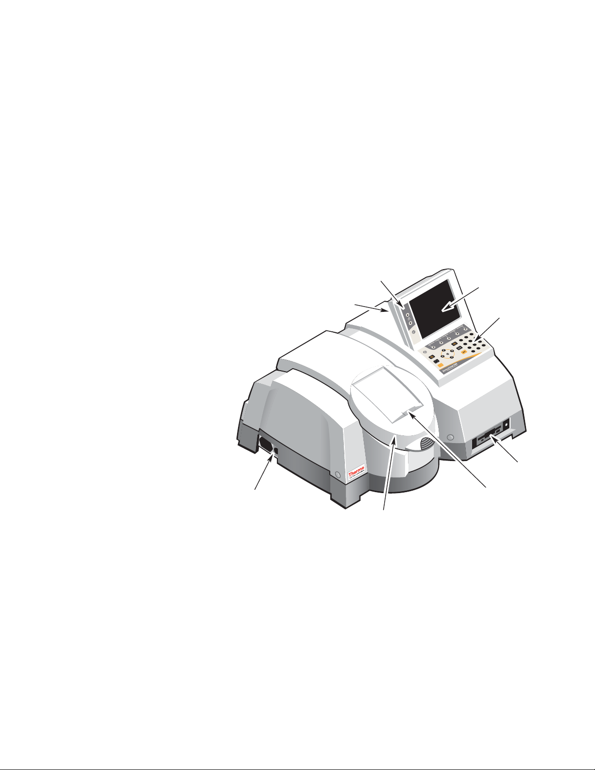
The following illustration identifies some major components visible on the
outside of a typical Evolution spectrophotometer. (Some components may
not be present on your spectrophotometer.)
Zero
Run
789
456
123
0
.-
Keypad
LCD screen
Contrast
Optional printer
Floppy dis
k
drive
Sliding door
Sample
compartment
Port for optional
power supply
Thermo Electron Corporation Evolution 300 and Evolution 600 User’s Guide 3

Chapter 2 Spectrophotometer Basics
Connectors The following illustrations show the locations of the connectors on each
side of the spectrophotometer.
Right side
Zero
Run
789
456
123
0
.-
PRINTER KEY BD EXT ACCY RS232 DISPLAY
EXT
Printer – Use to connect a printer with a parallel interface.
Key Bd – Use to connect an English keyboard (this is supplied by Thermo
Electron to meet electrical emission requirements).
Ext – Use to connect an external TTL (or contact closure) trigger.
Accy –Uses to connect an external accessory.
RS232 – Use to connect a computer with an RS232 interface.
Ext Display – Use to connect to a computer monitor.
4 Evolution 300 and Evolution 600 User’s Guide Thermo Electron Corporation
Chapter 2 Spectrophotometer Basics
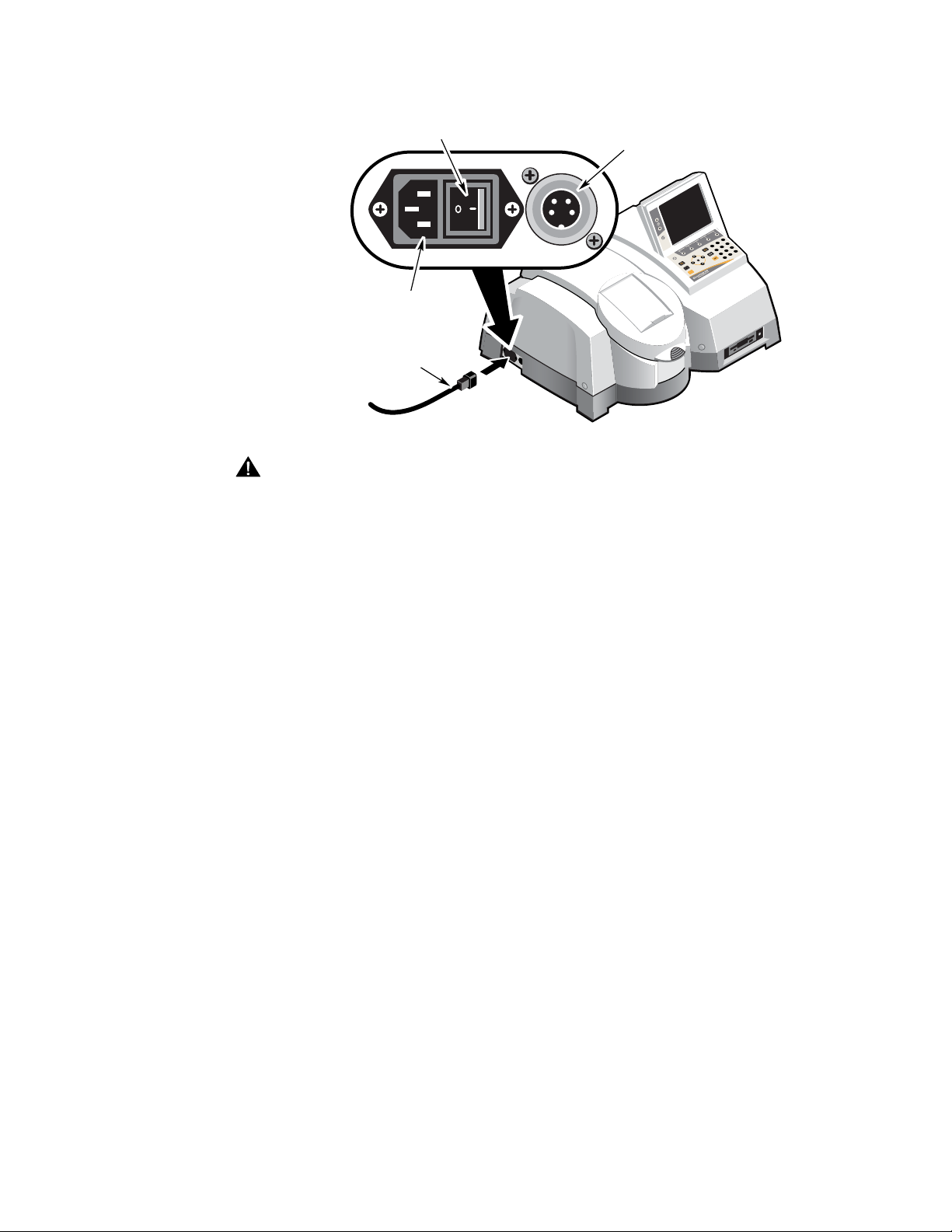
Left side
Port for optional
Peltier power supply
Power ON/OFF switch
Power supply
connection
Power cord
Zero
Run
789
456
123
0
.-
Danger Avoid shock hazard. Always power off the spectrophotometer and
disconnect the power supply from the wall outlet or power strip before
disconnecting the power supply from the spectrophotometer.
Thermo Electron Corporation Evolution 300 and Evolution 600 User’s Guide 5
Chapter 2 Spectrophotometer Basics
Connectors inside sample
compartment
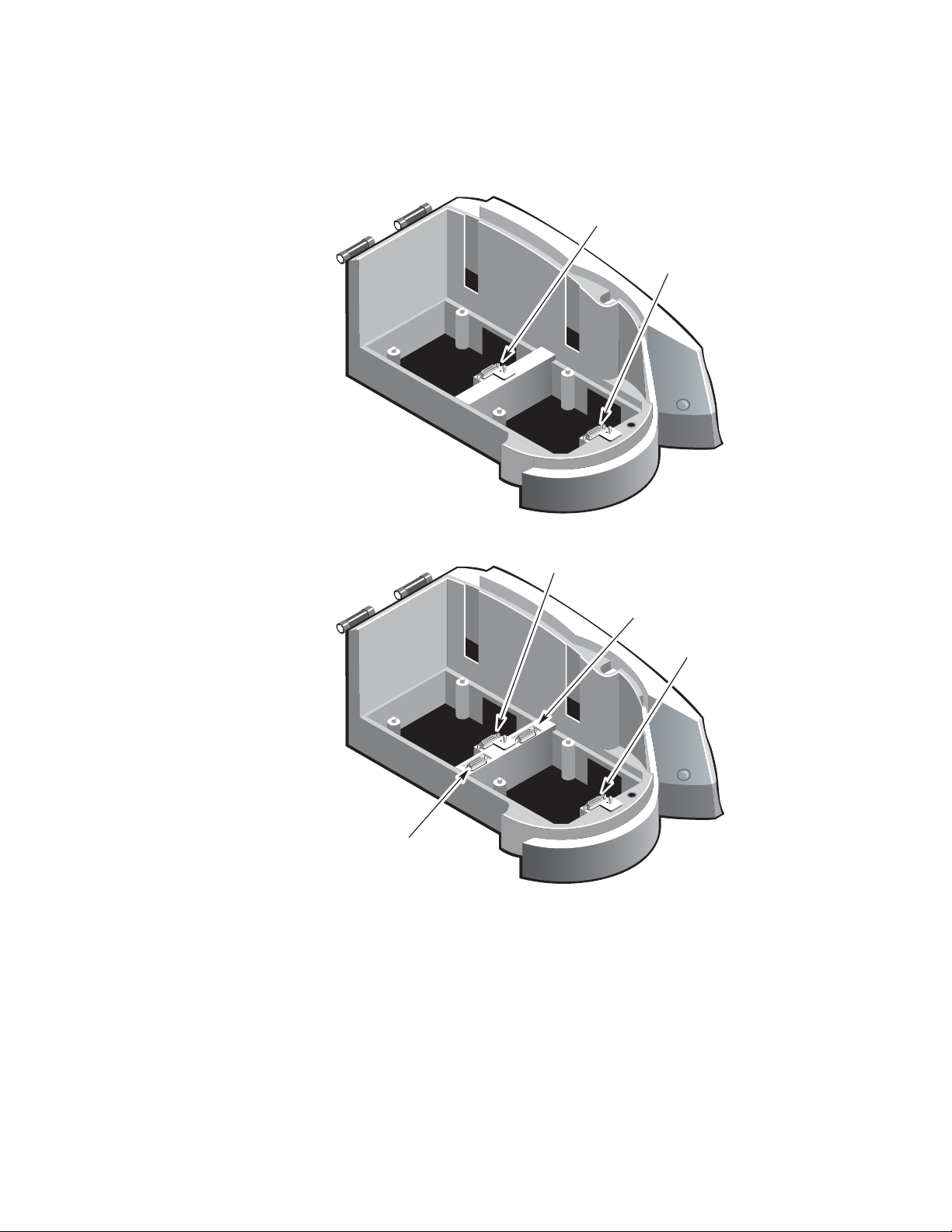
The following illustrations show the locations of the connectors inside the
sample compartment.
Evolution 300
Reference
connector
Sample
connector
Evolution 600
Sample
connector
Accessory/detector
connector
Accessory/detector
connector
Reference
connector
6 Evolution 300 and Evolution 600 User’s Guide Thermo Electron Corporation
This manual suits for next models
1
Table of contents
Other Thermo Electron Measuring Instrument manuals

Thermo Electron
Thermo Electron Cahn C-34 User manual

Thermo Electron
Thermo Electron Polysonics SX40 User manual

Thermo Electron
Thermo Electron Polysonics SX30 User manual

Thermo Electron
Thermo Electron 48C User manual

Thermo Electron
Thermo Electron EPD MK2 User manual

Thermo Electron
Thermo Electron Orion Star Series User manual

Thermo Electron
Thermo Electron Nicolet 380 User manual

Thermo Electron
Thermo Electron ELECTRA User manual

Thermo Electron
Thermo Electron PURE WATER Orion 1817LL User manual

Thermo Electron
Thermo Electron Orion 920Aplus User manual


