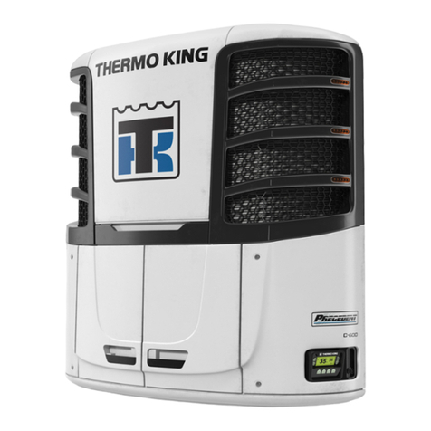
Thermo King T-500R User manual

TK 60484-1 (Rev. 6, 09-2016)
Ingersoll Rand Company Ltd. • Monivea Road • Mervue, Galway • Ireland
Maintenance Manual
Self-Powered Truck Units
T-500R
T-DAIRY
T-600R
T-800R
T-800R SPECTRUM
T-1000R
T-1000R SPECTRUM
T-1200R
T-1200R INTERMODAL
T-1200R SPECTRUM
UT-800
UT-1200
UT XTREME HIGH AMBIENT
UT SPECTRUM

-2
©2012-2016 Thermo King Ingersoll Rand Ltd., Monivea Road, Mervue, Galway • Ireland. All rights reserved.
Printed in Ireland.
The contents of this manual are the property of Thermo King and are copyrighted. No part of this document may be
reproduced or transmitted in any form or by an means, electronic or mechanical, for any purpose, without the express
written permission of Thermo King.
This maintenance manual is published for informational purposes only and the information should not be considered
as all-inclusive or covering all contingencies. If further information is required, Thermo King Europe should be
consulted. Information in this document is subject to change without notice.
Sale of product shown in this Maintenance Manual is subject to Thermo Kingís terms and conditions including, but
not limited to, the THERMO KING WARRANTY. Such terms and conditions are available on request.
The Thermo King warranty will not apply to any equipment which has been ìso repaired or altered outside the
manufacturerís plants as, in the manufacturerís judgment, to effect its stability.î
No warranties, express or implied, including warranties of fitness for a particular purpose or merchantability, or
warranties arising from course or dealing or usage of trade, are made regarding the information, recommendations
and descriptions contained herein. Manufacturer is not responsible and will not be held liable in contract or in tort
(including negligence) for any special, indirect or consequential damages, including injury or damage caused to
vehicles, contents or persons, by reason of the installation of any Thermo King product or its mechanical failure.
All other trademarks are the property of their respective owners.
Recover Refrigerant
At Thermo King we recognise the need to preserve the environment and limit the potential harm to the ozone layer that
can result from allowing refrigerant to escape into the atmosphere.
We strictly adhere to a policy that promotes the recovery and limits the loss of refrigerant into the atmosphere.
In addition, service personnel must be aware of Federal regulations concerning the use of refrigerants and the certification
of technicians. For additional information on regulations and technician certification programmes, contact your local
THERMO KING dealer.

Table of Contents
Introduction . . . . . . . . . . . . . . . . . . . . . . . . . . . . . . . . . . . . . . . . . . . . . . . . . . . . . . . . . 1-1
Safety Precautions . . . . . . . . . . . . . . . . . . . . . . . . . . . . . . . . . . . . . . . . . . . . . . . . . . . 2-1
Specifications . . . . . . . . . . . . . . . . . . . . . . . . . . . . . . . . . . . . . . . . . . . . . . . . . . . . . . . 3-1
Engine ...........................................................................................................................................3-2
Belt Tension..................................................................................................................................3-3
Engine Clutch ...............................................................................................................................3-4
Refrigeration System ....................................................................................................................3-5
Electrical Control System .............................................................................................................3-6
Fuses - (except T-500R/T-Dairy) .................................................................................................3-7
Fuses T-500R/T-Dairy..................................................................................................................3-7
Electrical Components..................................................................................................................3-8
Evaporator Fan Motors (UT-Series) .............................................................................................3-9
Electrical Standby T-Series (except T-500R/T-Dairy) (Model 50 Units Only) ...........................3-9
Electrical Standby UT-Series........................................................................................................3-10
Electrical Standby T-500R/T-Dairy..............................................................................................3-10
Electric Heater Strips (Optional) ..................................................................................................3-10
Maintenance Inspection Schedule . . . . . . . . . . . . . . . . . . . . . . . . . . . . . . . . . . . . . . 4-1
Unit Models: T-Series (Except T-500R) and T-Series Spectrum Host ........................................4-2
Unit Models: T-Series Spectrum ..................................................................................................4-4
Unit Models: T-500R....................................................................................................................4-5
Unit Models: UT1200 and UT-800 ..............................................................................................4-7
Unit Models: UT1200 and UT-800 Remote Evaporators.............................................................4-9
Unit Description . . . . . . . . . . . . . . . . . . . . . . . . . . . . . . . . . . . . . . . . . . . . . . . . . . . . . 5-1
General Description ......................................................................................................................5-2
Design Features.............................................................................................................................5-2
Unit Options..................................................................................................................................5-3
Engine ...........................................................................................................................................5-3
Standard HMI Control Panel ........................................................................................................5-3
Mechanics HMI Control Panel .....................................................................................................5-4
Premium HMI Control Panel (Optional) ......................................................................................5-4
CYCLE-SENTRYTM Start/Stop System.....................................................................................5-4
Defrost ..........................................................................................................................................5-5
DAS - Data Acquisition System (Optional - except on T-500R/T-Dairy) ...................................5-5
Electric Standby (Model 50 Units Only) ......................................................................................5-5
Engine Compartment Components...............................................................................................5-5
Unit Protection Devices ................................................................................................................5-6
Refrigeration System Components ...............................................................................................5-11
Single Temperature Refrigeration System Diagrams ...................................................................5-13
Multi-Temperature Refrigeration System Diagrams ....................................................................5-24
Operating Instructions Premium HMI . . . . . . . . . . . . . . . . . . . . . . . . . . . . . . . . . . . . 6-1
Controller Description ..................................................................................................................6-3
Starting the Diesel Engine ............................................................................................................6-10
Starting the Electric Motor ...........................................................................................................6-10
Switching from Diesel to Electric (Premium HMI only) .............................................................6-10
Switching from Electric to Diesel (Premium HMI only) .............................................................6-11
Defrost ..........................................................................................................................................6-11
Selecting High Speed Lockout Mode (If Enabled).......................................................................6-12
Selecting CYCLE-SENTRY or Continuous Mode ......................................................................6-13

Using the Gauges Key .................................................................................................................. 6-13
Using the Sensors Key.................................................................................................................. 6-14
Using The Main Menu.................................................................................................................. 6-15
Main Menu Choices ..................................................................................................................... 6-16
Languages..................................................................................................................................... 6-16
Alarms .......................................................................................................................................... 6-18
Datalogger .................................................................................................................................... 6-21
Hourmeters ................................................................................................................................... 6-21
Mode............................................................................................................................................. 6-22
Pretrip ........................................................................................................................................... 6-26
Diesel/Electric Menu .................................................................................................................... 6-28
Adjust Brightness ......................................................................................................................... 6-29
Time.............................................................................................................................................. 6-30
Operating Instructions Standard HMI . . . . . . . . . . . . . . . . . . . . . . . . . . . . . . . . . . . . 7-1
Controller Description .................................................................................................................. 7-2
Alarms .......................................................................................................................................... 7-13
Pretrip Test ................................................................................................................................... 7-14
Checking Truck HMI Control Panel Software Revision and Serial Number............................... 7-16
Electrical Maintenance . . . . . . . . . . . . . . . . . . . . . . . . . . . . . . . . . . . . . . . . . . . . . . . . 8-1
Alternator Charging System Diagnostic Procedures .................................................................... 8-2
Battery .......................................................................................................................................... 8-5
Fuses ............................................................................................................................................. 8-5
Smart FETs................................................................................................................................... 8-8
SMART REEFER 2/3 (SR-2/3) Microprocessor Controller........................................................ 8-8
Expansion Module (SPECTRUM systems ONLY [T-Series SPECTRUM
and UT SPECTRUM]) ................................................................................................................. 8-9
Flywheel (RPM) Sensor ............................................................................................................... 8-10
Glow Plugs ................................................................................................................................... 8-11
Unit Wiring................................................................................................................................... 8-12
AC Components (Model 50 Units Only)...................................................................................... 8-12
Overload Relay............................................................................................................................. 8-17
Engine Maintenance . . . . . . . . . . . . . . . . . . . . . . . . . . . . . . . . . . . . . . . . . . . . . . . . . . 9-1
EMI 2000...................................................................................................................................... 9-2
Engine Lubrication System .......................................................................................................... 9-2
Engine Air Cleaner (EMI 2000) ...................................................................................................9-3
Crankcase Breather System .......................................................................................................... 9-3
Engine Cooling System ................................................................................................................ 9-5
Engine Fuel System...................................................................................................................... 9-12
Adjust Engine Valve Clearance.................................................................................................... 9-29
Engine Mounts.............................................................................................................................. 9-32
Belts.............................................................................................................................................. 9-37
Refrigeration Maintenance . . . . . . . . . . . . . . . . . . . . . . . . . . . . . . . . . . . . . . . . . . . 10-1
Evacuation, Dehydration, and Charging ...................................................................................... 10-3
Refrigerant Leaks ......................................................................................................................... 10-12
Refrigerant Charge ....................................................................................................................... 10-12
Checking Compressor Oil ............................................................................................................ 10-12
Refrigeration System Checks ....................................................................................................... 10-13
Low Side Pump Down.................................................................................................................. 10-14
R-404A/R-452A/R-134A ............................................................................................................. 10-14
Refrigeration System Component Locations................................................................................ 10-16
Accumulator Replacement ........................................................................................................... 10-22
Reciprocating Compressor Replacement (T-Series) .................................................................... 10-23
TKO Scroll Compressor (UT-Series)........................................................................................... 10-25
Condenser Check Valve Test (Single Temperature Units Only) ................................................. 10-29

Condenser Check Valve and Purge Check Valve Test (T-500R/T-Dairy)...................................10-29
Condenser Check Valve, Purge Check Valve, and Receiver Tank Pressure Solenoid Leak
Test (Multi-Temp Units Only)......................................................................................................10-30
Condenser Inlet Solenoid (CIS) Test ............................................................................................10-31
Condenser/Radiator Coil Replacement.........................................................................................10-31
Dehydrator (Filter-Drier) Replacement ........................................................................................10-32
Discharge Pressure Regulator (DPR) Test....................................................................................10-32
Discharge Pressure Regulator (DPR) Replacement......................................................................10-30
Discharge Pressure Transducer Testing........................................................................................10-33
Discharge Pressure Transducer Replacement...............................................................................10-33
Discharge Strainer Test.................................................................................................................10-33
Discharge Strainer Replacement...................................................................................................10-34
Electronic Throttling Valve (ETV) Testing..................................................................................10-34
Electronic Throttling Valve (ETV) Replacement.........................................................................10-34
Evaporator Coil Replacement.......................................................................................................10-39
Expansion Valve Replacement .....................................................................................................10-40
Heat Exchanger Replacement.......................................................................................................10-41
High Pressure Cutout Switch (HPCO) Test..................................................................................10-41
High Pressure Cutout Switch (HPCO) Replacement....................................................................10-41
High Pressure Relief Valve Replacement.....................................................................................10-42
Hot Gas Bypass Solenoid (HGBS) Test .......................................................................................10-43
Hot Gas Solenoid (HGS) Test ......................................................................................................10-43
In-Line Check Valve Replacement...............................................................................................10-43
Liquid Injection Solenoid (LIS) Test............................................................................................10-44
Liquid Injection Solenoid (LIS) Replacement..............................................................................10-44
Liquid Line Solenoid (LLS) and Liquid Return Check Valve Test (Multi-Temp Units Only)....10-45
Low Pressure Cutout Switch (LPCO) Test (T-500R/T-Dairy Only)............................................10-45
Low Pressure Cutout Switch (LPCO) Replacement.....................................................................10-45
Purge Valve (PV) Test..................................................................................................................10-46
Receiver Tank Pressure Check Valve Test...................................................................................10-46
Receiver Tank Pressure Solenoid (RTPS) Test (Multi-Temp Units Only) ..................................10-46
Receiver Tank Replacement .........................................................................................................10-47
Solenoid Valve Replacement........................................................................................................10-47
Suction Line Check Valve Test (Multi-Temp Units Only) ..........................................................10-48
Suction Line Solenoid (SLS) Test (Multi-Temp Units Only) ......................................................10-48
Suction Pressure Regulator (SPR) Test ........................................................................................10-49
Suction Pressure Regulator (SPR) Replacement ..........................................................................10-49
Suction Pressure Transducer Testing (UT-Series and T-Series except T-500R/T-Dairy) ...........10-50
Suction Pressure Transducer Replacement...................................................................................10-50
Throttling Valve Test....................................................................................................................10-50
Throttling Valve Replacement and Repair ...................................................................................10-50
Clutch Maintenance . . . . . . . . . . . . . . . . . . . . . . . . . . . . . . . . . . . . . . . . . . . . . . . . . 11-1
Centrifugal Clutch.........................................................................................................................11-2
Clutch Maintenance ......................................................................................................................11-4
Structural Maintenance . . . . . . . . . . . . . . . . . . . . . . . . . . . . . . . . . . . . . . . . . . . . . . 12-1
Unit and Engine Mounting Bolts ..................................................................................................12-2
Unit Inspection..............................................................................................................................12-2
Condenser, Evaporator and Radiator Coils...................................................................................12-2
Micro-Channel Coil Cleaning Recommendations........................................................................12-2
Fan Location .................................................................................................................................12-4
Defrost Drains (UT-Series)...........................................................................................................12-4
Defrost Damper.............................................................................................................................12-4
Fanshaft Assembly........................................................................................................................12-5
Mechanical Diagnosis . . . . . . . . . . . . . . . . . . . . . . . . . . . . . . . . . . . . . . . . . . . . . . . . 13-1

Electric Standby Diagnosis . . . . . . . . . . . . . . . . . . . . . . . . . . . . . . . . . . . . . . . . . . . 14-1
Refrigeration System Diagnosis . . . . . . . . . . . . . . . . . . . . . . . . . . . . . . . . . . . . . . . 15-1
Remote Evaporators . . . . . . . . . . . . . . . . . . . . . . . . . . . . . . . . . . . . . . . . . . . . . . . . 16-1
Unit Description ........................................................................................................................... 16-2
Electrical Maintenance ................................................................................................................. 16-7
Structural Maintenance................................................................................................................. 16-7
Remote Evaporator System Diagnosis ......................................................................................... 16-7
Wiring Diagrams and Wiring Schematics . . . . . . . . . . . . . . . . . . . . . . . . . . . . . . . 17-1

1 Introduction
ABOUT THIS MANUAL
The information in this manual is provided to assist owners, operators and service people in the proper upkeep and maintenance
of Thermo King units. Each unit family includes many specific models. When maintenance information differs between models
within a unit family, this manual uses specific unit model nomenclature. When maintenance information for specific models
within a unit family is the same, this manual uses unit family nomenclature.
THE MAINTENANCE INFORMATION IN THIS MANUAL COVERS MODELS:
Unit Family Specific Unit Models
T Series
T-1200R, T-1200R SPECTRUM, T-1000R, T-1000R SPECTRUM, T-800R, T-800R
SPECTRUM, T-600R, T-500R
UT-Series UT-1200, UT SPECTRUM, UT-800, UT Xtreme High Ambient
T-Series UT-Series
T-500R 30 SR (901907) UT-800 30 SR3 200/1/60 (902131)
T-500R 50 SR (901908) UT-800 50 SR3 230/1/60 (902174)
T-500R 50 SR 400/3/50 (901911) UT-800 50 SR3 400/3/50 (902098)
T-600R 30 SR (901361) UT-800 50 SR3 460/3/60 (902133)
T-600R 50 SR (901420) UT-1200 50 SR3 200/1/60 (902099)
T-800R 30 SR (901423) UT-1200 50 SR3 230/1/60 (902173)
T-800R 50 SR (901424) UT-1200 50 SR3 400/3/50 (902079)
T-800R 50 SR 230/3/60 (901425) UT-1200 50 SR3 460/3/60 (902132)
T-800R 50 SR 400/3/50 (901426) UT-1200 SR3 400/3/50 R134A (903368)
T-1000R 30 SR (901427) UT-1200 SR3 230/3/60 R134A (903385)
T-1000R 50 SR 230/3/50 (901428) UT SPECTRUM 208V/3/60 (903360) 2 ZONE
T-1000R 50 SR 230/3/60 (901429) UT SPECTRUM 220V/3/50 (903361) 2 ZONE
T-1000R 50 SR 400/3/50 (901431) UT SPECTRUM 230V/3/60 (903362) 2 ZONE
T-1200R 30 SR (901432) UT SPECTRUM 400V/3/50 (903363) 2 ZONE
T-1200R 50 SR 230/3/50 (901433) UT SPECTRUM 208V/3/60 (903379) 3 ZONE
T-1200R 50 SR 230/3/60 (901434) UT SPECTRUM 220V/3/50 (903380) 3 ZONE
T-1200R 50 SR 400/3/50 (901435) UT SPECTRUM 230V/3/60 (903381) 3 ZONE
T-800R SPECTRUM 30 SR (901566) UT SPECTRUM 400V/3/50 (903382) 3 ZONE
T-800R SPECTRUM 50 SR 230/3/50 (901567)
T-800R SPECTRUM 50 SR 230/3/60 (901568)
T-800R SPECTRUM 50 SR 400/3/50 (901569)
T-1000R SPECTRUM SR (901571) 2 ZONE
T-1000R SPECTRUM 50 SR 230/3/50(901572) 2 ZONE
T-1000R SPECTRUM 50 SR 230/3/60 (901573) 2 ZONE
T-1000R SPECTRUM 50 SR 400/3/50 (901574) 2 ZONE
T-1000R SPECTRUM SR (901575) 3 ZONE
T-1000R SPECTRUM 50 SR 230/3/50(901576) 3 ZONE
T-1000R SPECTRUM 50 SR 230/3/60 (901577) 3 ZONE
T-1000R SPECTRUM 50 SR 400/3/50 (901578) 3 ZONE
T-1200R SPECTRUM 30 SR (901579) 2 ZONE
T-1200R SPECTRUM 50 SR 230/3/60 (901582) 2 ZONE
T-1200R SPECTRUM 50 SR 400/3/50 (901583) 2 ZONE
T-1200R SPECTRUM 30 SR (901579) 3 ZONE
T-1200R SPECTRUM 50 SR 230/3/50 (901581) 3 ZONE
T-1200R SPECTRUM 50 SR 230/3/60 (901582) 3 ZONE
T-1200R SPECTRUM 50 SR 400/3/50 (901583)3 ZONE

Introduction 1-2
OTHER REFERENCE MANUALS
For detailed descriptions of Thermo King engines, compressors or temperature control systems, refer to the appropriate Thermo
King manual:
Operating Manuals
Parts Manuals
Diagnosis, Installation, Overhaul and Refrigeration Maintenance Manuals
Self-Powered Truck Units T-500R, T-600R, T-800R,
T-1000R, T-1200R, T-Series SPECTRUM
TK 60483
Self-Powered Undermount Truck Units UT-800, UT-1200,
UT SPECTRUM
TK 60652
T-500R Parts Manual TK 55306
T-Dairy Parts Manual TK 55654
T-600R Parts Manual TK 54559
T-800R Parts Manual TK 54545
T-1000R Parts Manual TK 54546
T-1200R Parts Manual TK 54449
T-800R SPECTRUM Parts Manual TK 54566
T-1000R SPECTRUM Parts Manual TK 54839
T-1200R SPECTRUM Parts Manual TK 54819
UT-1200 Parts Manual TK 53568
UT-800 Parts Manual TK 55366
UT SPECTRUM Parts Manual TK 61416
T-Series ST Installation Manual TK 54354
T-Series MT Installation Manual TK 54481
UT-Series Undermount Systems Installation Manual TK 60712
UT SPECTRUM Installation Manual TK 61415
Truck TSR Single Temperature Microprocessor Control
System
TK 54843
Truck SR-3 Single Temp Diagnostic Manual TK 55208
Truck SR-2/SR-3 Multi Temp Diagnostic Manual TK 54293
Truck SR-2 Single Temp Diagnostic Manual TK 54292
Diagnosing TK Truck and Trailer Refrigeration Systems TK 60201
TK270, TK370 and TK 376 Engine Overhaul Manual TK 53163
Principles of Evacuation for Field Application TK 40612
Tool Catalog TK 5955
X214, X418, X426 and X430 Compressor Overhaul TK 6875
ElectroStatic Discharge (ESD) Training Guide TK 40282

Safety Precautions 2-1
2 Safety Precautions
Thermo King recommends that all service be performed by a Thermo King dealer. However, you should be aware of several
general safety practices:
GENERAL PRACTICES
1. ALWAYS WEAR GOGGLES OR SAFETY GLASSES. Refrigerant liquid and battery acid can permanently damage the
eyes (see First Aid).
2. Never close the compressor discharge service valve with the unit operating. Never operate the unit with the compressor
discharge valve closed. This condition increases internal pressure, which can cause an explosion.
3. Keep your hands clear of the fans and belts when the unit is operating. This should also be considered when opening and
closing the compressor service valves.
4. Make sure the gauge manifold hoses are in good condition. Never let them come in contact with a belt, fan motor pulley, or
any hot surface.
5. Never apply heat to a sealed refrigeration system or container.
6. Fluorocarbon refrigerants, in the presence of an open flame or electrical short, produce toxic gases that are severe respiratory
irritants.
7. Make sure all mounting bolts are tight and are of the correct length for their particular application.
8. Use extreme caution when drilling holes in the unit. The holes may weaken structural components, and holes drilled into
electrical wiring can cause fire or explosion.
9. Use caution when working around exposed coil fins. The fins can cause painful lacerations.
10. Use caution when working with a refrigerant or refrigeration system in any enclosed or confined area with a limited air supply
(for example, a truck body or garage). Refrigerant tends to displace air and can cause oxygen depletion which may result in
unconsciousness or death from suffocation.
11. Use caution and follow the manufacturer’s suggested practices when using ladders or scaffolds.
AUTO START/STOP CONTROLS
Units equipped with a CYCLE-SENTRY Automatic Start-Stop system may start automatically at any time when the unit is on
and CYCLE-SENTRY is the selected mode. Be sure to turn the On/Off switch “Off” before opening unit service doors or
inspecting or working on any part of the unit.
BATTERY INSTALLATION AND CABLE ROUTING
1. Improperly installed battery could result in a fire or explosion! A Thermo King approved battery must be installed and
properly secured to the battery tray.
2. Improperly installed battery cables could result in fire or explosion! Battery cables must be installed, routed and secured
properly to prevent them from rubbing, chaffing or making contact with hot, sharp or rotating components.
3. Do not attach fuel lines or any additional wiring harnesses to the battery cables as this could cause an electrical fire!
4. Do not connect other manufacturer’s equipment or accessories to the Thermo King unit. This could result in severe damage
to equipment and void the warranty!
5. Set all unit electrical controls to the OFF position before connecting battery cables to the battery to prevent unit from starting
unexpectedly and causing personal injury.
6. Always wear protective clothing, gloves and eye wear when handling and installing batteries. Battery acid can cause serious
burns when exposed to eyes or skin. If battery acid contacts skin or clothing, wash immediately with soap and water. If acid
enters your eye, immediately flood it with running cold water for at least twenty minutes and get medical attention
immediately.
7. Always cover battery terminals to prevent them from making contact with metal components during battery installation.
Battery terminals grounding against metal could cause the battery to explode.

Safety Precautions 2-2
BATTERY REMOVAL
DANGER: Disconnect the negative battery terminal (-) first when removing a battery. Connect the
positive terminal (+) first when installing a battery.
This order is important because the frame is grounded to the negative battery terminal. If the negative
terminal is still connected, a complete circuit exists from the positive terminal of the battery to the frame.
Metal objects contacting the positive side and the frame simultaneously will cause sparks or arcing. If
there are sufficient hydrogen gases emitted from the battery, an explosion might occur, causing equipment
damage, serious injury, even death.
REFRIGERANT
General Information
When removing refrigerant from a unit, a recovery process that prevents or minimises refrigerant loss to the atmosphere is
required by law.
Do not use oxygen (O2) or compressed air for leak testing. Oxygen mixed with refrigerant is combustible.
Do not use a Halide torch. When a flame comes in contact with refrigerant, toxic gases are produced. These gases can cause
suffocation, even death.
When a refrigerant is exposed to the atmosphere in the liquid state, it evaporates rapidly, freezing anything it contacts. If
refrigerant contacts the skin, severe frostbite can result.
First Aid
In the event of frost bite, the objectives of First Aid are to protect the frozen area from additional injury, to warm the affected
area rapidly, and to maintain respiration.
• EYES: For contact with liquid, immediately flush eyes with large amounts of water and get prompt medical attention.
• SKIN: Flush area with large amounts of lukewarm (not hot) water. Do not apply heat. Remove contaminated clothing and
shoes. Wrap burns with dry, sterile, bulky dressing to protect from infection/injury. Get medical attention. Wash contaminated
clothing before reuse.
• INHALATION: Move victim to fresh air and use cardiopulmonary resuscitation or mouth-to-mouth ventilation if necessary.
Stay with victim until arrival of emergency medical personnel.
REFRIGERANT OIL
General Information
Observe the following precautions when working with or around synthetic or polyol ester refrigerant oil:
• Do not allow refrigerant oil to contact your eyes.
• Do not mix refrigerant oils because that can cause system damage.
• Do not allow prolonged or repeated contact with skin or clothing.
• To prevent irritation, you should wash thoroughly immediately after handling refrigerant oil. Rubber gloves are recommended
when handling polyol ester oil.
First Aid
• EYES: Immediately flush eyes with large amounts of water for at least 15 minutes while holding the eyelids open. Get prompt
medical attention.
• SKIN: Remove contaminated clothing. Wash thoroughly with soap and water. Get medical attention if irritation persists.
• INHALATION: Move victim to fresh air and restore breathing necessary. Stay with victim until arrival of emergency
personnel.
• INGESTION: Do not induce vomiting. Contact a local poison control center or physician immediately.

Safety Precautions 2-3
ELECTRICAL
Microprocessor Service
Precautions must be taken to prevent electrostatic discharge when servicing the microprocessor controller and related
components. Potential differences considerably lower than those which produce a small spark from a finger to a door knob can
severely damage or destroy solid-state integrated circuit components.
The following procedures must be rigidly adhered to when servicing units to avoid microprocessor damage or destruction.
1. Disconnect all power to the unit.
2. Avoid wearing clothing that generates static electricity (wool, nylon, polyester, etc.).
3. Do wear a static discharge wrist strap (TK P/N 204-622) with the lead end connected to the microprocessor’s ground terminal.
These straps are available at most electronic equipment distributors. DO NOT wear these straps with power applied to the unit.
4. Avoid contacting the electronic components on the circuit boards of the unit being serviced.
5. Leave the circuit boards in their static proof packing materials until ready for installation.
6. If a defective controller is to be returned for repair, it should be returned in the same static protective packing materials from
which the replacement component was removed.
7. After servicing the controller or any other circuits, the wiring should be checked for possible errors before restoring power.
Welding of Units or Truck Bodies
When electric welding is to be performed on any portion of the temperature control unit, truck or truck chassis when the
temperature control unit is attached, it is necessary to ensure that welding currents are NOT allowed to flow through the electronic
circuits of the unit.
These procedures must be rigidly adhered to when servicing units to avoid damage or destruction of the controller.
1. Disconnect all power to the unit.
2. Disconnect all wire harnesses from the controller.
3. Switch all of the electrical circuit breakers in the control box to the OFF position.
4. Weld unit and/or container per normal welding procedures. Keep ground return electrode as close to the area to be welded as
practical. This will reduce the likelihood of stray welding currents passing through any electrical or electronic circuits.
5. When the welding operation is completed, the unit power cables, wiring and circuit breakers must be restored to their normal
condition.
High Voltage
When servicing or repairing a temperature control unit, the possibility of serious or even fatal injury from electrical shock exists.
Extreme care must be used when working with a refrigeration unit that is connected to a source of operating power, even if the
unit is not operating. Lethal voltage potentials can exist at the unit power cord, inside the control box, at the motors and within
the wiring harnesses.
Low Voltage
Control circuits used in the temperature control unit are low voltage (24 volts ac and 12 volts dc). This voltage potential is not
considered dangerous, but the large amount of current available (over 30 amperes) can cause severe burns if shorted or grounded.
Do not wear jewelry, watch or rings. These items can short out electrical circuits and cause severe burns to the wearer.

Safety Precautions 2-4
Precautions
1. Be certain the unit On/Off switch is turned OFF before connecting or disconnecting the standby power plug. Never attempt
to stop the unit by disconnecting the power plug.
2. Be certain the unit power plug is clean and dry before connecting it to a power source.
3. When working on high voltage circuits on the temperature control unit, do not make any rapid moves. If a tool drops, do not
grab for it. People do not contact high voltage wires on purpose. It occurs from an unplanned movement.
4. Use tools with insulated handles that are in good condition. Never hold metal tools in your hand if exposed, energised
conductors are within reach.
5. Treat all wires and connections as high voltage until a meter and wiring diagram show otherwise.
6. Never work alone on high voltage circuits on the temperature control unit. Another person should always be present to shut
off the temperature control unit and provide aid in the event of an accident.
7. Have electrically insulated gloves, cable cutters and safety glasses available in the immediate vicinity in the event of an
accident.
First Aid
IMMEDIATE action must be initiated after a person has received an electrical shock. Obtain immediate medical assistance if
available.
The source of shock must be immediately removed by either shutting down the power or removing the victim from the source.
If it is not possible to shut off the power, the wire should be cut with either an insulated instrument (e.g., a wooden handled axe
or cable cutters with heavy insulated handles) or by a rescuer wearing electrically insulated gloves and safety glasses. Whichever
method is used, do not look at the wire while it is being cut. The ensuing flash can cause burns and blindness.
If the victim has to be removed from a live circuit, pull the victim off with a non-conductive material. Use the victim’s coat,
a rope, wood, or loop your belt around the victim’s leg or arm and pull the victim off. DO NOT TOUCH the victim. You can
receive a shock from current flowing through the victim’s body. After separating the victim from power source, check
immediately for the presence of a pulse and respiration. If a pulse is not present, start cardiopulmonary resuscitation and call for
emergency medical assistance. If a pulse is present, respiration may be restored by using mouth-to-mouth resuscitation, but call
for emergency medical assistance.

Safety Precautions 2-5
UNIT DECALS
Serial number decals, refrigerant type decals and warning decals appear on all Thermo King equipment. These decals provide
information that may be needed to service or repair the unit. Service technicians should especially read and follow the instructions
on all warning decals.
T-Series Refrigerant Decal Locations
1. Below the fuel filters, inside the engine access
door.
2. On the evaporator beside the expansion valve.
3. Beside the serial number plate on top of the unit
frame above the switch panel.
4. On the top of the condenser coil.
tkrsmd31
UT-Series Refrigerant Decal Locations
1. On accumulator tank.
2. On front of frame above compressor.
ARA2505
1
2
Refrigerant Decal
refdec-NT

Safety Precautions 2-6
Warning Decals
2e24151g0

3 Specifications
Engine. . . . . . . . . . . . . . . . . . . . . . . . . . . . . . . . . . . . . . . . . . . . . . . . . . . . . . . . . . . . 3-2
Belt Tension . . . . . . . . . . . . . . . . . . . . . . . . . . . . . . . . . . . . . . . . . . . . . . . . . . . . . . . 3-3
Engine Clutch. . . . . . . . . . . . . . . . . . . . . . . . . . . . . . . . . . . . . . . . . . . . . . . . . . . . . . 3-4
Refrigeration System. . . . . . . . . . . . . . . . . . . . . . . . . . . . . . . . . . . . . . . . . . . . . . . . 3-5
Electrical Control System . . . . . . . . . . . . . . . . . . . . . . . . . . . . . . . . . . . . . . . . . . . . 3-6
Fuses - (except T-500R/T-Dairy) . . . . . . . . . . . . . . . . . . . . . . . . . . . . . . . . . . . . . . . 3-7
Fuses T-500R/T-Dairy . . . . . . . . . . . . . . . . . . . . . . . . . . . . . . . . . . . . . . . . . . . . . . . 3-7
Electrical Components . . . . . . . . . . . . . . . . . . . . . . . . . . . . . . . . . . . . . . . . . . . . . . 3-8
Evaporator Fan Motors (UT-Series) . . . . . . . . . . . . . . . . . . . . . . . . . . . . . . . . . . . . 3-9
Electrical Standby T-1000R/T-1200R/T-1000R Spectrum/T-1200R Spectrum (Model 50 Units
Only) . . . . . . . . . . . . . . . . . . . . . . . . . . . . . . . . . . . . . . . . . . . . . . . . . . . . . . . . . . . . . 3-9
Electrical Standby T-600R/T-800R/T-800R Spectrum . . . . . . . . . . . . . . . . . . . . . . 3-9
Electrical Standby UT-Series . . . . . . . . . . . . . . . . . . . . . . . . . . . . . . . . . . . . . . . . 3-10
Electrical Standby T-500R/T-Dairy . . . . . . . . . . . . . . . . . . . . . . . . . . . . . . . . . . . . 3-10
Electric Heater Strips (Optional). . . . . . . . . . . . . . . . . . . . . . . . . . . . . . . . . . . . . . 3-10

Specifications 3-2
ENGINE
Model: T-500R/T-Dairy
T-600R, T-800R, RT-800R, T-800R SPECTRUM
T-1000R,T-1000R SPECTRUM, T-1200R,T-1200R
SPECTRUM,
UT-800, UT-1200, UT XTREMEHIGH Ambient, UT
SPECTRUM
TK 270
TK370
TK376 (Tier 2 Euro 4)
TK376U
Fuel Type No. 3 Biofuel compatibility Max. B7
No. 2 Diesel fuel under normal conditions
No. 1 Diesel fuel is acceptable cold weather fuel
Oil Capacity:
T1200R, T1000R Crankcase & Oil Filter
T1200R, T1000R w/Bypass Oil Filter
T-500R/T-Dairy Crankcase & Oil Filter
T-500R/T-Dairy w/Bypass Oil Filter
T600R and T800R Crankcase & Oil Filter
T600R and T800R w/Bypass Oil Filter
UT-Series w/Bypass Oil Filter
11.0 liters Fill to full mark on dipstick
12.0 liters. Fill to full mark on dipstick
3.7 litres Fill to full mark on dipstick
4.0 litres. Fill to full mark on dipstick
8.5 liters Fill to full mark on dipstick
9.5 liters. Fill to full mark on dipstick
12.1 liters. Fill to full mark on dipstick
Oil Type API Classification CI-4 or better
(ACEA Rating E3 or better for Europe)
Oil Viscosity -10 C to 50 C: SAE 15W-40 (Synthetic)
-15 to 40 C: SAE 15W-40
-25 to 40 C: SAE 10W-40
-25 to 30 C: SAE 10W-30
-30 to 0 C: SAE 5W-40 (Synthetic)
Below -30 C: SAE 0W-30 (Synthetic)
Engine rpm: T-Series Low Speed Operation 1650 ± 25 rpm
T-Series High Speed Operation (except T-500R/
T-Dairy) 2250 ± 25 rpm
T-500R/T-Dairy High Speed Operation 2300 ± 25 rpm
UT-800 Low Speed Operation 1450 ± 25 rpm*
UT-800 High Speed Operation 2200 ± 25 rpm
UT-1200/UT XTREMEHIGH Ambient/UT
SPECTRUM Low Speed Operation 1625 ± 25 rpm*
UT-1200/UT XTREMEHIGH Ambient/UT
SPECTRUM High Speed Operation 2425 ± 25 rpm
Engine Oil Pressure 138 to 345 kPa (20 to 50 psig) in low speed
276 to 414 kPa (40 to 60 psig) in high speed
Intake Valve Clearance 0.15 to 0.25 mm
Exhaust Valve Clearance 0.15 to 0.25 mm
Valve Setting Temperature 21 C
Fuel Injection Timing 16 ± 1 degrees BTDC
Injection Nozzle Pressure 12,300 to 13,300 kPa (1784 to 1929 psig)
Low Oil Pressure Switch/Sensor 69 ± 14 kPa (10 ± 2 psig) —shutdown
High Coolant Temperature Sensor 104 ± 3 C (220 ± 5 F)—shutdown
Engine Thermostat 71 C (160 F)
* UT series engine low speed setting, can dip too low when under load - if this occurs, please refer to Bulletin
SB 944 for more details

Specifications 3-3
Engine Coolant Type ELC (Extended Life Coolant), which is “RED”
Use a 50/50 concentration of any of the following
equivalents:
Chevron Dex-Cool
Texaco ELC
Havoline Dex-Cool®
Havoline XLC for Europe
Shell Dexcool®
Shell Rotella
Saturn/General Motors Dex-Cool®
Caterpillar ELC
Detroit Diesel POWERCOOL® Plus
CAUTION: Do not add “GREEN” or “BLUE-GREEN”
conventional coolant to cooling systems using “RED”
Extended Life Coolant. In an emergency deionized
water can be used but must be replaced with the
correct coolant as soon as possible.
Coolant System Capacity T-1200R, T-1000R
Coolant System Capacity T-800R, T-600R
Coolant System Capacity T-500R
Coolant System Capacity T-Dairy
Coolant System Capacity UT-Series
6.2 liters with coolant expansion tank
5.7 liters with coolant expansion tank
5.2 liters with coolant expansion tank
Coolant Expansion Tank Cap Pressure
T-Series
UT-Series 103 kPa (15 psig)
48kPa (7 psig)
BELT TENSION
Belt Tension No.
on TK Gauge
P/N 204-427
Frequency Gauge P/N
204-1903
New (Hz) Run-In (Hz)
Water Pump Belt 40
Engine/Electric Motor (Jackshaft)
T-500R/T-Dairy
T-600R, T-800R, T-1000R, T-1200R
T-800R, T-1000R, T-1200R SPECTRUM
UT-Series 65-75
79
69
59
70-75
55-60
45-50
Electric Motor (Jackshaft)/Compressor
T-500R/T-Dairy
UT-Series 65-75 146 146
T-1000R
T-1200R
T1000R SPECTRUM
T1200R SPECTRUM
See page 9-33 thru’ 9-35 for details
Alternator (UT-Series only) 45-55
Note: Refer to relevant chapter for correct belt tension procedure.
Note: Most recent models of T-Series Units now generally use plates for setting the tension - see Chapter 9 for
correct belt tension procedures.
ENGINE (CONTINUED)

Specifications 3-4
ENGINE CLUTCH
Engagement 600 ± 100 RPM
Dynamic Torque 66 fT-lb (89.5 N•m) minimum @ 1600 RPM

Specifications 3-5
REFRIGERATION SYSTEM
Caution: Fluorinated Refrigerant gases should not be ventilated to atmosphere.
T-Series units from end of 2015 are available with R-404A or R-452A Refrigerants. Both of which comply with F-Gas
legislation revision 2014 (Regulation (EC) No 517/2014)
NOTE: Please take note of your refrigerant type (label on outside of unit), and make sure not to cross-contaminate.
Refrigerant GWP
R-404A 3922
R-452A 2140
Compressor Model
T-500R/T-Dairy, T-600R, T-800R,
T-1000R
T-1200R
UT-Series
Thermo King X214 Deep Sump
Thermo King X426 LSC5
Thermo King X430 LSC5
TK06 Scroll 6 HP
Refrigerant Charge
T-800R/T-1000R/T-1200R SPECTRUM (Host)
T-1200R, T-1000R
T-800R
T-600R
T-500R
T-Dairy
UT-Series (Host)
4.11 kg (9.06 lb) **
3.5 kg (7.7 lb) R-404A/R-452A
3.2 kg (7 lb) R-404A/R-452A
2.5 kg (5.5 lb) R-404A/R-452A
2.4 kg (5.3 lb) R-134A
4.11 kg (9.06 lb) **
*Compressor Oil Charge
T-Series (except T-500R/T-Dairy)
T-500R/T-Dairy
UT-Series
4.1 liters (4.3 quarts)
3.0 litres (3.2 quarts)
1.86 liters (1.97 quarts)
Compressor Oil Type Ester base P/N 203-513 required for Reciprocating
Compressor
Ester base P/N 203-516 required for Scroll Compressor
Suction Pressure Regulator Valve Setting:
T-500R/T-Dairy
T1000R
T800R
T600R
T1000R Spectrum
T800R Spectrum
190 to 210 kPa (28 to 31 psig)
140 to 160 kPa (21 to 23 psig)
240 to 260 kPa (35 to 37 psig)
190 to 210 kPa (28 to 31 psig)
140 to 160 kPa (21 to 23 psig)
240 to 260 kPa (35 to 37 psig)
Throttling Valve Setting:
T-Series and UT-Series 220 to 234 kPa (32 to 34 psig)
Discharge Pressure Regulator Valve Setting:
All Except UT XTREMEHIGH Ambient
UT XTREMEHIGH Ambient
Discharge Pressure Regulator Valve Setting
2413 ± 34 kPa (350 ± 5 psig)
1276 ± 34 kPa (185 ± 5 psig)
High Pressure Cutout Switch R-404A/R-452A:
Open
Close
***High Pressure Cutout Switch R-134A: Open
Close
3241 ± 48 kPa (470 ± 7 psig)
2586 ± 262 kPa (375 ± 38 psig)
2320 ± 70 kPa (337 ± 10 psig)
1380 ± 140 kPa (200 ± 20 psig)
* When the compressor is removed from the unit, oil level should be noted or the oil removed from the
compressor should be measured. This is to be sure that the same amount of oil can be added before placing the
replacement compressor in the unit.
** See “Charging procedure for T-Spectrum & UT units. ” on page 10-10 for refrigerant charge calculation for
Multi-Temperature Self-Powered Truck units.
*** UT XTREMEHIGH Ambient unit uses the same settings as the R404A/R452A units.

Specifications 3-6
ELECTRICAL CONTROL SYSTEM
Control System Voltage 12.5 Vdc
Battery
12 Volt,
Standard, Silver Calcium, AHr Rating - 75 AHrs, 640 Cold
Cranking Amps at -18 C (0F) (ENCCA)
Option: EON - AHr Rating - 68 AHrs, 880Cold Cranking
Amps at -18 C (0F) (ENCCA)
Battery Charging System
T-Series (except T-500R/T-Dairy)
T-500R/T-Dairy
UT-800
T-800R SPECTRUM
T-1000R/T-1200R SPECTRUM
UT-1200/UT SPECTRUM
12 volt, 37 amp, brush type, Thermo King alternator
12 volt, 65 amp, brush type, Thermo King alternator
12 volt, 120 amp, brush type, Thermo King alternator
Voltage Regulator Setting 13.8 to 14.4 volts @ 25 C (77 F)
NOTE: Fuse F4 (Bypass resistor for Prestolite Alternator) must be removed for the Thermo King
Alternator.
This manual suits for next models
13
Table of contents
Other Thermo King Truck manuals