THERMOBILE PROHEAT 18 User manual

THERMOBILE
I N D U S T R I E S B V
Konijnenberg 80
NL
-4825 BD BREDA
Tel: +31 (0)76
- 587 34 50
Fax: +31 (0)76
- 587 27 89
USER'S MANUAL ELECTRIC HEATER PROHEAT
18
EEC remark
This appliance meets the required EEC directives: Machine directive 89/392/EEC
Low Voltage Directive 73/23/EEC
First print January 2004 no. 40.020.895 rev. 0

2
Table of contents
1PREFACE .......................................................................................................................3
2UNPACK.........................................................................................................................3
3GUARANTEE CONDITIONS AND LIABILITY...........................................................................3
4TECHNICAL DATA............................................................................................................4
Components of the electric heater....................................................................................................4
General data......................................................................................................................................4
Electrical data....................................................................................................................................4
Air-related data..................................................................................................................................4
5SAFETY AND ENVIRONMENT.............................................................................................5
5.1 Icons used in the manual ..................................................................................................5
5.2 General safety regulations.................................................................................................5
6INSTALLATION.................................................................................................................6
7USE AND OPERATION ......................................................................................................7
Advice................................................................................................................................................7
Electric heater not in use...................................................................................................................7
Ventilation of the ambient air.............................................................................................................7
Heating of the ambient air.................................................................................................................7
Heating and constant ventilation of the ambient air ..........................................................................7
Use of the room thermostat...............................................................................................................7
Switch off the electric heater.............................................................................................................7
8MAINTENANCE................................................................................................................7
9TROUBLE SHOOTING.......................................................................................................8
10 WIRING DIAGRAM PROHEAT 18.....................................................................................9
11 MATERIALS LIST 80-04-05............................................................................................12

3
1 PREFACE
Dear customer,
Thank you for purchasing the ELECTRIC
HEATER PROHEAT 18. This heater is
designed for heating air, for instance in
houses, buildings, site offices and workshops.
Your new ELECTRIC HEATER has many
advantages.
Carefully follow the instructions in this manual
and carry out maintenance activities on a
regular basis.
Regular maintenance results in an enhanced
reliability with the emphasis on safety.
Besides, it will lengthen the life span of the
heater.
This manual contains various warnings and
instructions. Therefore carefully read the
manual and act accordingly.
Only by meticulously following the instructions
dangerous situations that may cause personal
injury or damage the ELECTRIC HEATER
can be avoided.
Trained personnel may only carry out
maintenance activities and repairs.
2 UNPACK
1 Remove the packaging.
2 The packaging contains the following
components:
- Electric heater
- User's manual
3 Inspect the electric heater for any
damage.
4 Read the user's manual.
5 Now you can install the electric heater in
accordance with chapter 6 of this user's
manual.
3 GUARANTEE CONDITIONS AND LIABILITY
The customer is entitled to 12 months warranty
towards the manufacturer, subject to the
conditions given below.
•The guarantee period comes into effect on
the date of delivery of the electric heater to
the buyer.
•Any transport costs related to
sending arising from a claim to guarantee
are at the customer's expense.
•Any call out charges are at the expense of
the customer. The guarantee is no longer
valid if the appliance has been modified by
any other than the manufacturer or not in
accordance with the instructions of the
manufacturer.
•The guarantee is exclusively valid if the
electric heater has been installed and is
used and maintained in compliance with
the instructions of the manufacturer.
•Guarantee is excluded in case of defects
caused by:
- overdue maintenance or negligence
- repair by an incompetent person
- improper use
- modifications of the appliance
This is at the discretion of the
manufacturer.
The guarantee is only applicable to defects
that have been discovered during the
guarantee period, insofar these defects are
based on material or manufacturing faults
(at the discretion of the manufacturer or an
unbiased expert).
•Only use original parts for replacements.
•The liability of the manufacturer for defects
is explicitly limited to compliance with the
guarantee obligations described above.
All claims to compensation for any reason,
except the reason for non-compliance with
the guarantee obligations, are excluded.
•Consequential damage of any nature
caused by the electric heater is excluded.
•These guarantee conditions are generally
binding.
•We shall not accept any obligations
towards and arrangements with third
parties.
4
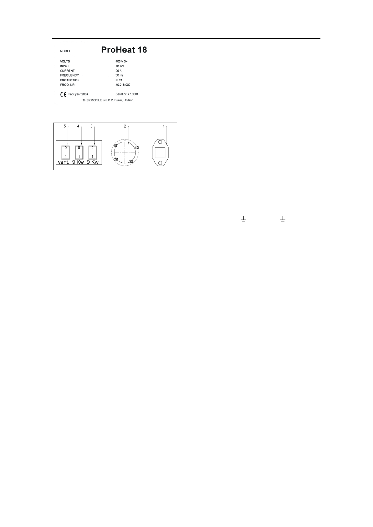
4 TECHNICAL DATA
Type plate
thermostat
black red red
room
thermostat
drawing 1 PROHEAT 18
The electric heater consists of a sheet steel
housing in which a ventilator and six stainless
steel heating elements have been mounted in
a fully shrouded way.
The heating part has been provided with
overheating protections that deactivate the
heating elements when the temperature
becomes too high.
Components of the electric heater
1 Connection point room thermostat
2 Control thermostat
3 On/of switch heating, 9 kW
4 On/of switch heating, 9 kW
5 On/of switch ventilator
Type: PROHEAT 18
General data
depth 585 mm
width incl. wheels 535 mm
total height 945 mm
weight 40 kg
protection level IP 21
direction of rotation of ventilator always OK
Electrical data
supply voltage 400 V 3~
frequency 50 Hz
position
current
power
capacity
from
motor
0.6 A 250 W
9 kW
13 A
9 kW
7800 kcal/h
18 kW
26 A
18 kW
15600 kcal/h
power supply cable H07RN-F 4 x 4 mm²
plug 3p. + or 3p.+N+ 32 A
fuse max. 35 A
Air-related data
air speed 17 m/s
air output 1000 m³/h
temperature increase 120° C
maximum ambient temperature 40º C
The technical data mentioned have been
rounded.
5
5 SAFETY AND ENVIRONMENT
It is necessary to carefully read the instructions
for use before using the electric heater and to
follow the instructions.
5.1 Icons used in the manual
Point of attention.
5.2 General safety regulations
•If you are not familiar with the electric
heater yet, we advise you to first carefully
read the manual and study the instructions
one by one.
•Competent and trained employees who
have read the manual for this appliance
may only operate the electric heater.
•Competent persons include persons who
have been informed about the dangers
resulting from improper use.
•Never use the electric heater in rooms
where there is a risk of explosions.
•Always connect the electric heater to a
standard earthed socket 400 V 3 ~ 50 Hz,
fused with a maximum of 35 A. The socket
must comply with the standard that applies
in the country concerned.
Attention
When using a plug 3P+N+
, do
not use the ZERO.
You should connect the blue wire
to a phase.
See chapter 6.
•Changing the phase wires will not affect
the proper operation of the electric heater.
•If you need an extension cable, make sure
that this is earthed and of the correct type.
Improper or defective extension cables can
lead to serious danger.
Warning for a faulty action that
may result in fatal injury or
damage of the electric heater.
•The fact that the electric heater is
functioning properly does not mean that the
electric heater has been earthed nor that it
has been safely installed. Consult a
recognised expert to be absolutely sure.
•A trained and authorised person may only
do repair and maintenance of the
appliance.
•Do not place any objects within a distance
of 150 cm in front of the air outlet.
•Never cover or obstruct the air inlet and/or
outlet. Do not insert any objects into the air
inlet.
•Do not place or install the electric heater in
the rain and do not use when the air
humidity is above 85%.
•Always observe the applicable local safety
regulations to prevent danger and
accidents.
•If you detect visible defects, immediately
disconnect the power supply and repair it
(e.g. power supply cable damaged).
•It is forbidden to install the appliance in the
direct vicinity of inflammable material or to
cover the appliance.
•During repair always use original parts that
comply with the current safety standards.
Parts of other manufacturers that appear to
fit at first sight may jeopardize the safety.
•Authorised and trained personnel may only
carry out repairs and maintenance
activities.
•Before starting the maintenance activities,
disconnect the power supply.
•Never remove the housing of the electric
heater while the electric heater is
connected to the power supply.
•Never clean the electric heater with water.
•Make sure that the Safety and
Environment regulations are observed in
accordance with the local standards.
•When producing the electric heater all
materials used were carefully selected in
order to burden the environment as little as
possible.
•Therefore the electro technical parts mainly
consist of metals in which plastics have
been incorporated to a small extent.
These parts can without any problems be
offered to a processing company for re-
use.
6
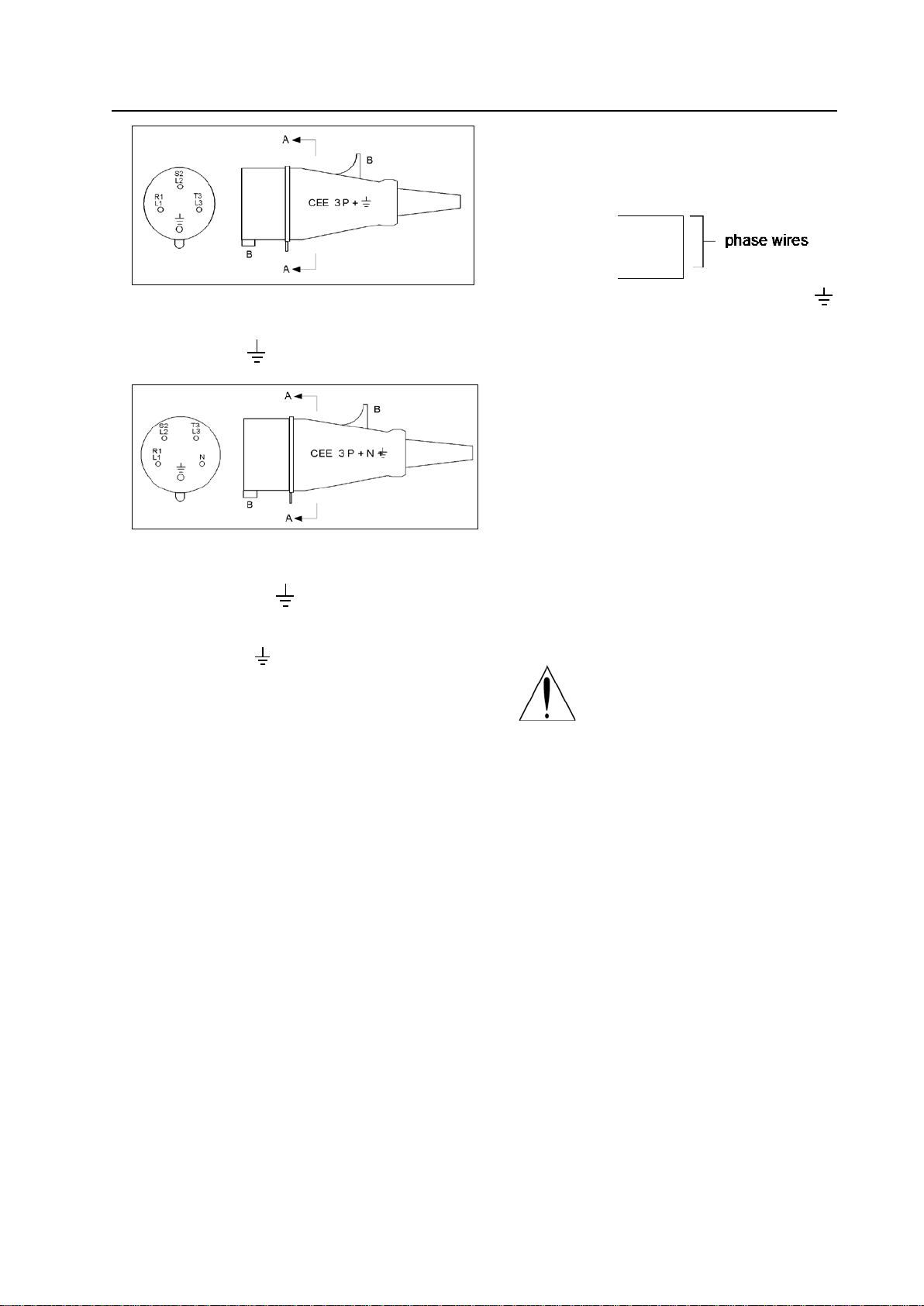
6 INSTALLATION
A: view A-A, seen from the inside
B: cam
CEE plug - 3P + 32 A
A: view A-A, seen from the inside
B: cam
CEE plug - 3P + N + 32 A
1 Check whether the mains voltage
is 400 V 3~ + 50 Hz.
If not, do not connect the electric heater.
2 If the electric heater has not been
provided with a power plug, mount this
following the instruction below:
- Disassemble the plug. Loosen the
screws of the terminals and the pull
relief. If necessary, cut the tulle to size.
- Slide the housing over the cable.
- Cut the cores (if necessary) to the
correct length for the terminals and
mount the cores as follows:
-
green/yellow = earth wire
(most important wire)
L1 or R1
L2 or S2
L3 or T3
brown
black
blue
N Do NOT use (with 3P+N+ )
In this case blue can be used as phase.
See NEN 1010 chapter 51, art. 514.3.4.
Exchanging the colours brown, black and
blue will not affect the operation of the
electric heater.
3 Securely tighten the screws of the
terminals and, subsequently, of the pull
relief. Place the housing on the interior
work and screw it on.
4 Before connecting the electric heater to
the power socket, set the switches 3+4+5
to position 0 (off). See Use and operation,
chapter 7.
5 Set the switch to the required position.
See Use and operation, chapter 7.
If you use an extension cable,
pay attention to the advised
voltage loss of the extension
cable of 10 V. See the table
below.
4 mm²
50 m
26 A
9 V
6 mm²
100 m
26 A
12.5 V
Fully unwind cable reels, if used.
7
7 USE AND OPERATION
Use the electric heater just for heating air. For
example, use the electric heater for heating or
drying houses, buildings, site offices and
workshops. You can also use the electric
heater for speeding up drying processes of,
for example, paintwork and plasterwork.
Advice
The best and quickest drying result is
achieved when you install the electric heater
below and open a window above.
thermostat
black red red
room
thermostat
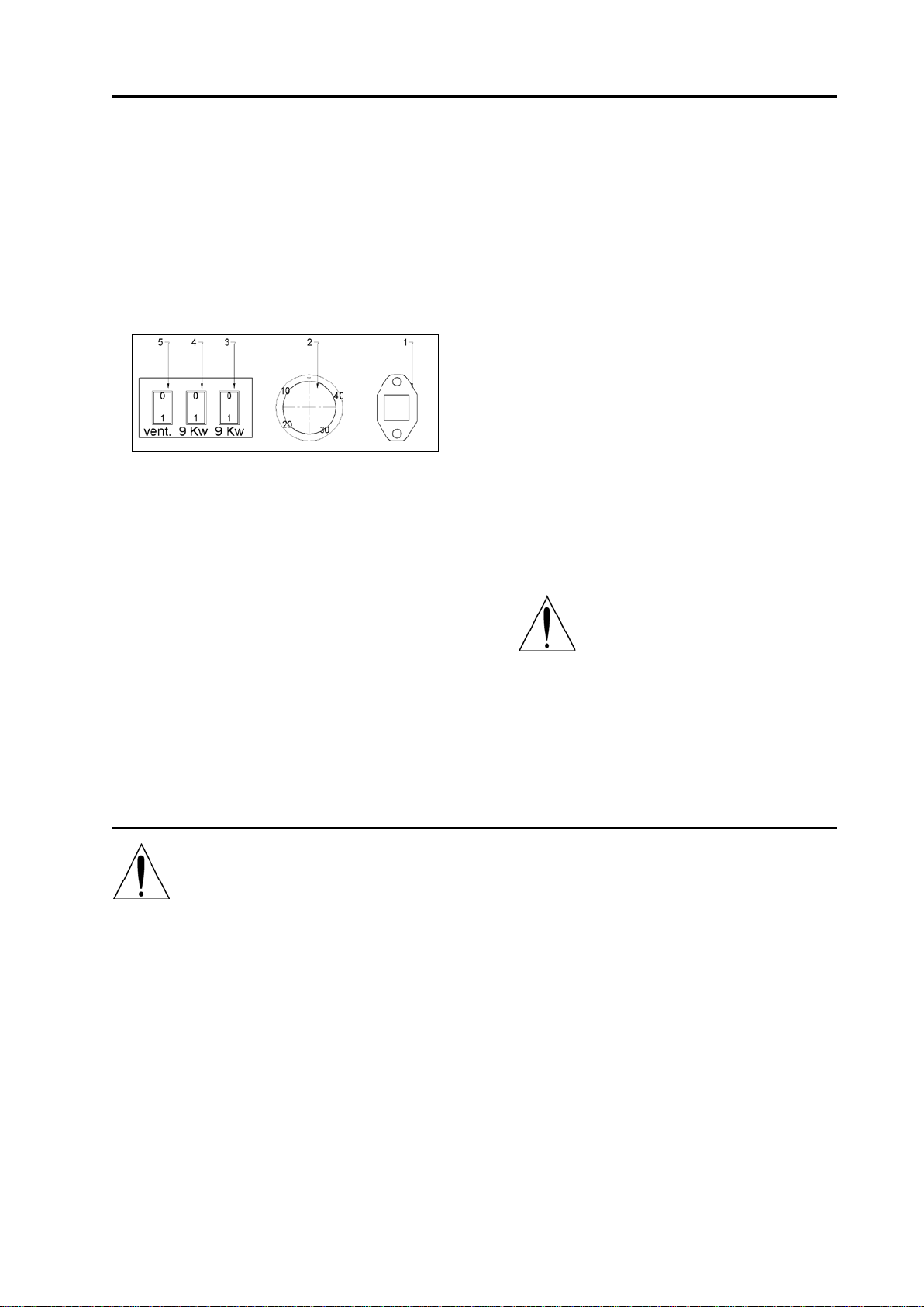
Operating panel PROHEAT 18
Electric heater not in use
Set the switches 5 (ventilator), 3 (heating
9 kW) and 4 (heating 9 kW) to position '0' to
switch off the electric heater.
Ventilation of the ambient air
Set the switch 5 (ventilator) to position 'I' and
switch 3 (heating 9 kW) and switch 4 (heating
9 kW) to position '0'. The thermostat (2) will
not become active.
Heating of the ambient air
Set the switch 3 (heating 9 kW) and/or switch
4 (heating 9 kW) to position 'I'. Set the switch
5 (ventilator) to position '0'.
Set the thermostat to the required
temperature.
After the thermostat (2) has switched off the
heating, the ventilator will stop after after-
cooling.
Heating and constant ventilation of the
ambient air
Set the switch 5 (ventilator) to position 'I'. Set
the switch 3 (heating 9 kW) and/or 4 (heating
9 kW) to position 'I'. Set the thermostat to the
required temperature. After the thermostat (2)
has switched off the heating, the ventilator will
keep running constantly.
Use of the room thermostat
If the room thermostat (1) has been
connected, the heater thermostat (2) must be
on maximum.
Switch off the electric heater
When switching off the heater,
set the switches 5, 4 and 3 to
position '0'.
Leave the plug in the socket for
another 5 minutes for after-
cooling.
8 MAINTENANCE
Before starting the maintenance
activities, disconnect the power
supply.
Remove the rear panel from the electric
heater by unscrewing all screws.
Clean the inside of the electric heater with
compressed air. Make sure that the fan
blade is cleaned well.
Carefully loosen very persistent dirt with a
screwdriver. Make sure that everything is
removed, otherwise the ventilator can get
out of balance. This will cause vibrations
that will seriously affect the life span of the
bearings.
Never clean the inside with water.
Clean the housing with a moist cloth. After
that let the housing dry or wipe it dry. Place
the housing on the electric heater again.
Touch up any damage of the coating.
We constantly aim at improving our
products. Changes resulting from this are
without reservation and without the
obligation to change the heaters that have
already been put in the market.
8
9 TROUBLE SHOOTING
The electric heater has been composed of high-quality parts and will function for 10 years under
normal conditions.
Fault
Possible cause
Solution
Ventilator runs and the indicator
lamp in the heating switch is lit
(electric heater is cold)
Temperature protection or
heating element defect
Relay defect
Wiring loose
(see remark 2)
Ventilator runs and the indicator
lamp in the heating switch (3
and/or 4) is not lit (electric
heater is cold)
Thermostat set loo low. Switch
(3 and/or 4) for heating not
switched on.
Set the thermostat higher.
Set the switch(es) to 'I'.
Ventilator does not run
Heater gives warmth
Ventilator defect
Wiring loose
(see remark 2)
Ventilator runs slowly
Heater gives warmth
Fuse defect
(see remark 3)
Check the fuses in the
distribution box (see remark 1)
At plug 3P + N + the blue
wire has been attached to the N
instead of to a phase
Check the plug and connect the
blue wire to L1, L2 or L3 (see
remark 1)
Ventilator runs normally, heater
gives less warmth than usual
One fuse defect means 50% of
the warmth
(see remark 3)
Check the fuses in the meter
cupboard (see remark 1)
At plug 3P + N + the blue
wire has been attached to the N
instead of to a phase
Check the plug and connect the
blue wire to L1, L2 or L3 (see
remark 1)
Heating elements defect
Technical defect (see remark 2)
Electric heater does not react
Electric heater does not receive
any power
Check whether the power plug is
in the socket.
Check the fuses
Check whether the connecting
cable has been interrupted (see
remark 1)
Electric heater does not react
Internal fuse is defect, 2 A slow
500 V (6.3 x 32)
Check the heater and replace
the fuse (see remark 2)
Electric heater does not react
Guard is not on the room
thermostat connection
Place the guard on the
thermostat connection.
Room thermostat connected
and electric heater does not
react
Heater thermostat is not on
maximum
Set the heater thermostat to
maximum.
Remark 1) When you cannot remedy the fault, contact a recognised professional.
Remark 2) Contact the supplier of your electric heater.
Remark 3) When one fuse is defect, the heater will deliver 50% of the set value.
9
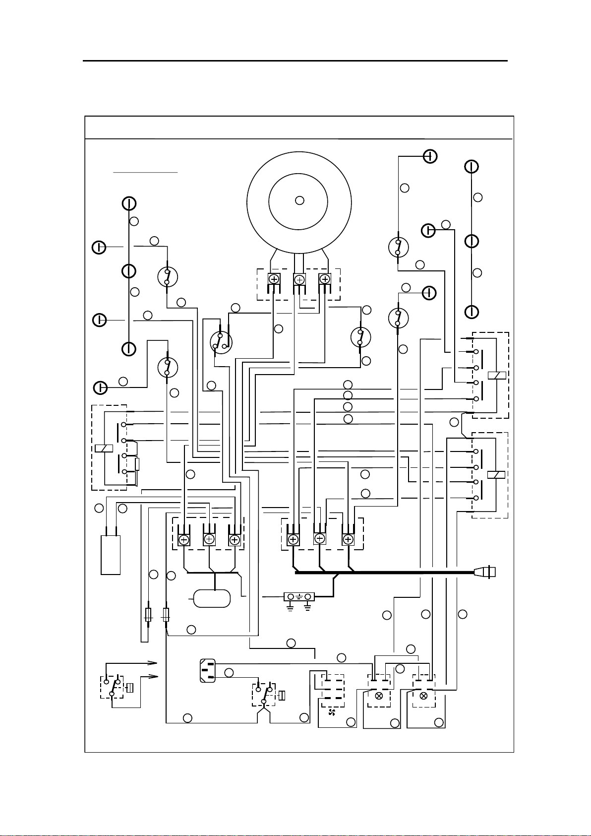
10WIRING DIAGRAM PROHEAT 18
400 V 3~ 50 Hz
1000 m³/h 17 m/s
Wiring 2½ mm²
Black
Grey
Red
8
11
12
9
4
5
6
15
16
28
25
29
Black
Brown
26
27
10
Black
Relais 2 - 9 kW
Relais 3 - 9 kW
T
S
R
T
S
R
21
18
20
22
19
13 14
23
24
1
1
2
2
3
25 A
4
2
8
6
0
1
25 A
230 V
3 kW
3 kW
3 kW
3 kW
3 kW
25 A
4
2
8
6
0
1
25 A
230 V.
3 kW
3 kW
3 kW
3 kW
3 kW
3 kW
3 kW
Motor 230 V.
250 VA.50 Hz
HR 07 RN-F
4 X 4 mm²
30
Brown
17
Brown
T
S
R
Blue
M5
1232
1 3
SFK 3
M5
Capacitor
500 V ~
8 µF
7
SFK 3F
M5
1
2
45°C.
4
2
8
6
0
1
R
Black
Brown
Red
Brown
32
31
36
38
37
39
40 Blue
Grey
Transformer
Brown
170 V. 230 V.
ST
Grey
Grey
Blue
White
Black
Brown
CEE 5P. 32 A
Black
Black
Black
Brown
Brown
Brown
Green-
White
Blue
Brown
Wiring.Sif 2,5 mm²
Yellow
After Cool
Black
Grey
Grey
Grey
Grey
Blue
White
Fuse 6,3 x 32
max. 2 A slow 500 V
Grey
Brown
R2
R3
R1
1
3
2
ST
63°C
25 A
1
63°C
25 A
2
63°C
25 A
3
63°C
25 A
4
63°C
25 A
5
3
Green-
Yellow
400V.3~
P
12
0-38°C
9 kW 9 kW
4 1
63
52
I
O4 1
52
I
O41
52
I
O
34
33 35
Blue
Grey
Grey Grey
41
Switch 1 Switch 2 Switch 3
400 Volt 3~ 50Hz. 18 kw. 26 Amp.
WIRING DIAGRAM Proheat 18
White
White
Black
Black
Black
Brown
White
Blue
Grey
Red
Bijwerk datum:17-12-2003
E1
E1
E2
E3
E2
E3
E4
E5
E6
E4
E5
E6
P
12
Thermostat
Interne
40
Blue
Grey
Externe
Thermostat
E
10A.250VL
0
Black
Black
Black
250 VA
Black
42

10

11

12
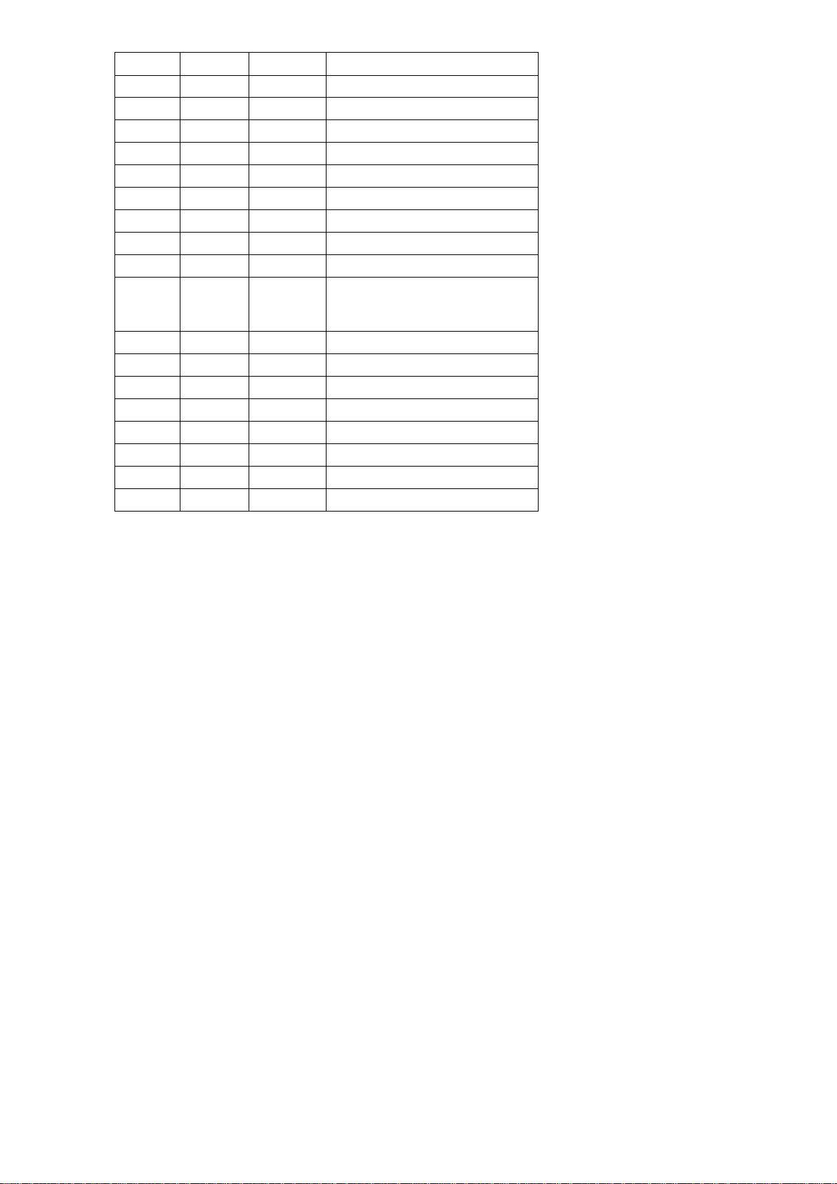
11MATERIALS LIST 80-04-05
--------------------------------------------------------------------------------------------------------------------------------------
Pos. Number Description
--------------------------------------------------------------------------------------------------------------------------------------
61 1 Motor with centr. fan 230 V~ 50 Hz 250 W
62 1 Mounting bracket for motor
63 1 Capacitor 8 µF 500 V~
64 2 Air inlet rim
65 1 Voltage monitoring relay 2-pole + resistance
66 3 Stainless steel heating elements 230 v 3 kW
67 3 Stainless steel heating elements 230 v 3 kW.
68 12 IT 400 gasket rings 19 x 13 x 2 mm
69 12 Brass nut ¼ Gas x 5½ mm pitch 19 mm
70 1 Max. Clixon thermostat 63°C.
71 1 After-cooling Clixon thermostat 45°C 16 A built-in change-over contact
72 1 Regulating thermostat 0-40°C 16 A change-over
73 1 Thermostat covering ring chrome
74 1 Thermostat knob black 40 mm round
75 2 Relay 2-pole 25 A 230 V~ + mounting brackets
76 1 Cable H07RN-F 4x4 mm² l =2,75 m with 4 x bush 4x10
77 1 Connector strip for 7 x 3 Fastons SFK7 HF KR with
78 1 Insulation plate under SFK7 HF KR 224 x 103 mm
80 1 Front plate with outblow 150 round epoxied Grey Ral 7022 Hg.
81 1 Rear side with 2 x 6 air inlet slots epoxied Grey Ral 7022 Hg.
82 1 Bottom plate epoxied Grey Ral 7022 Hg.
83 1 Cover 2 x 5 x 6 inlet slots epoxied Red Ral 3003 Hg.
84 1 Steel tube frame black
85 2 Wheels 160 mm rubber tyre and fastening material
86 1 Type plate PROHEAT 18 100 x 40 mm
87 4 Max. Clixon thermostat 63°C 25 A wall-mounted
88 1 Fibreglass-enforced polyamide perfect swivel Pg 21
89 1 Nut Pg 21
90 2 On/of tumbler switch red 2-pole with lamp
91 1 Change-over switch tumbler black 2-pole
92 1 Cover plate 231 x 670 mm
93 1 Ring core transformer 400/230 V~ 250 VA
94 1 Connector strip for 3 x 3 Fastons SFK 3F KR
95 1 Transformer plate with fastening and insulation
96 2 Fuse holder 6.3 x 32
97 2 Fuses 6.3 x 32 2 A slow 500 V
13
Pos. no. number EDP no. description
1 1 40018025 Interior work 18 kW assembly
2 1 40018013 Fastening plate
3 1 40018012 Guard
4 -
5 1 40018024 Cooling plate
6
1
40018010
Mantle
7 2 40018031 Plastic handle
8 1 40018011 Rear panel
9 1 40018022 Handle
10 1 40202091
40202092
40226030
Room thermostat connection
11 1 40018019 Wheel shaft
12 2 40501672 Washer
13
2
40202142
Wheel
14
2
40202101
Locking ring
15 2 40202102 Dust cover
16 1 40018014 Footrest
17
18
Table of contents
Other THERMOBILE Electric Heater manuals


Popular Electric Heater manuals by other brands

Thermo Sphere
Thermo Sphere QGW08-608 manual

BLACK DECKER
BLACK DECKER BHRO608 instruction manual

MrHeater
MrHeater BIG Buddy MH18B Operating instructions and owner's manual

Comfort Zone
Comfort Zone CZ550 Series quick start guide

MrHeater
MrHeater MHQ60FAV Operating instructions and owner's manual

Thermo Sphere
Thermo Sphere FW550-15A instruction manual

bemodern
bemodern BM06 User & installation instructions

Firesense
Firesense 2117 Operating Instructions & TroubleShooting Guideline

Elite
Elite EH1464 instructions

bemodern
bemodern 1640 installation instructions

Intertec Data Systems
Intertec Data Systems CP VARITHERM ... BI Series quick start guide

KALOS
KALOS KLEH101-0100 Assembly instructions


