bemodern 1640 User manual
200701_1 Page 1
1640 / 1640-50 / 1640-50 Portrait Models 2kw Electric Heater User /
Installation Instructions
These instructions should be read carefully and retained for future reference
Important Notes
•This heater must not be located immediately below a fixed socket outlet.
•Do not use the heater in the immediate surrounds of a bath, a shower, or a swimming pool.
•Do not cover this heater, or obstruct the air inlet or outlet, otherwise there is a risk of
overheating.
•The heater must be cooled down completely before any maintenance
•This heater must be fixed against a vertical surface.
•Under no circumstances should the heater be used as a free standing appliance.
•After unpacking, please make sure that the appliance is intact, with no signs of damage caused by transport. If in
doubt, do not use the appliance and contact the Service Centre.
•During normal operation this appliance will emit noise from the internal fan unit.
•If the supply cord is damaged, it must be replaced by the manufacturer, its service agent or similarly qualified
persons in order to avoid a hazard.
•Children should be supervised to ensure that they do not play with the appliance or handset
•Children of less than 3 years should be kept away unless continuously supervised. Children aged from 3 years and
less than 8 years shall only switch on/off the appliance provided that it has been placed or installed in its intended
normal operating position and they have been given supervision or instruction concerning use of the appliance in a
safe way and understand the hazards involved. Children aged from 3 years and less than 8 years shall not plug in,
regulate and clean the appliance or perform user maintenance.
•This appliance can be used by children aged from 8 years and above and persons with reduced physical, sensory or
mental capabilities or lack of experience and knowledge if they have been given supervision or instruction
concerning use of the appliance in a safe way and understand the hazards involved. Cleaning and user
maintenance shall not be made by children without supervision
•Some parts of this product can become very hot and cause burns. Particular attention has to be given where
children and vulnerable people are in the vicinity.
•Do not use this appliance as a primary heat source
•Ensure that furniture, curtains and other combustible materials are positioned no closer that 1m from the front of the
fire.
•Do not stand the fire on the carpet –stand on a firm surface, which is free of dust and lint.
•If this fire is supplied through an extension cable, please ensure that it is the only appliance plugged into the
extension and that the instructions for the extension cable / reel are followed.
•CAUTION: In order to avoid a hazard due to inadvertent resetting of the thermal cut out, this appliance must not be
supplied through an external switching device, such as a timer, or connected to a circuit that is regularly switched on
and off by the utility.
•This appliance must be positioned so that the plug / fused spur is accessible
•In the event of a fault please disconnect the fire from the mains supply
•If the fire is to be placed in front of an existing chimney opening and there is any risk of chimney debris falling down
onto the fire it is recommended that the flue or opening is sealed off with non-combustible non-fibrous insulation
materials. Do not place into an existing fireplace that is prone to dampness. Should it be necessary to cap and seal
the chimney to prevent personal injury, a professional should be hired to do the work
•Warning: This appliance must be earthed.
•If the fire is to be placed in front of an existing chimney opening and there is any risk of chimney debris falling down
onto the fire or drafts from the chimney it is recommended that the flue or opening is sealed off with non-combustible
non-fibrous insulation materials. Do not place into an existing fireplace that is prone to dampness. Should it be
necessary to cap and seal the chimney to prevent personal injury, a professional should be hired to do the work
The wires in the mains lead connected to this appliance are coloured in accordance with the following code:
Green and Yellow Earth
Blue Neutral
Brown Live
As the colour of the wires in the mains lead of this appliance may not correspond with the coloured markings identifying
the terminals in your plug, proceed as follows. The wire which is coloured Green and Yellow must be connected to the
terminal in the plug which is marked with the letter E or by the earth symbol or coloured Green or Green and Yellow. The
wire which is coloured Blue must be connected to the terminal which is marked with the letter N or coloured Black. The
wire which is coloured Brown must be connected to the terminal which is marked with letter L or coloured Red.

200701_1 Page 2
For indoor use only. Do not use outdoors. This appliance is only suitable for well insulated
spaces or occasional use.
Please unpack carefully ensuring that any loose parts and all packing items are removed. Read any warning labels carefully (see
Maintenance Section). Place waste packaging back into box and dispose of RESPONSIBLY.
The surround/appliance must be positioned so that plug (fused spur) is accessible. Only when you are certain that you
have completed the installation should you plug in and switch on at the wall socket.
Suite Installation
Before You Start
Parts Identification:
Suite Unit (A) –Showing fire fixing points Fire (B) –Showing fire fixing points
(Suite Design shown for example only) (Fire Available in Various heights)
Fixing Brackets (C) 5/8” Screws (D) Remote Control (E) No.6 x 1/2” Screw (F)
•Check and make sure you have all the parts as listed above. If not, contact: Be-Modern Helpline on 0191 430-
0901.
•The appliance Data Plate is located on the front of the flame effect housing on the fire unit behind the glass panel.
•Check that the supply voltage details on your flame effect fire are in accordance with your electrical supply. Your
fire is fitted with a plug incorporating a 13 Amp fuse. In the event of replacing the fuse in the plug supplied, a 13
Amp fuse approved by ASTA to BS 1362 must be used. Before switching on, please read the following fire
installation instructions.
•Prior to installation please remove the transit pads at the base of the Suite “A” if fitted.
•Place Suite “A” in the required position and remove any obstructions, i.e. cut to shape or remove skirting to allow
the Suite to butt up flush against the wall (if required). Remember to allow enough space when cutting the skirting
for the cable to exit from the desired side.
Parts supplied (Timber / MDF):
A: 1 off Timber / MDF Suite
B: 1 off electric fire
C: 2 off Each Fixing Brackets (if required)
D: 4 off 5/8” screws (if required)
E: 1 off Remote Control
Parts supplied (Marble):
A: 1 off Marble Suite unit
B: 1 off Fire unit
E: 1 off Remote Control, inc battery and
PVC battery cover
F: 4 off No.6 x 1/2 “ Pan head screws
200701_1 Page 3
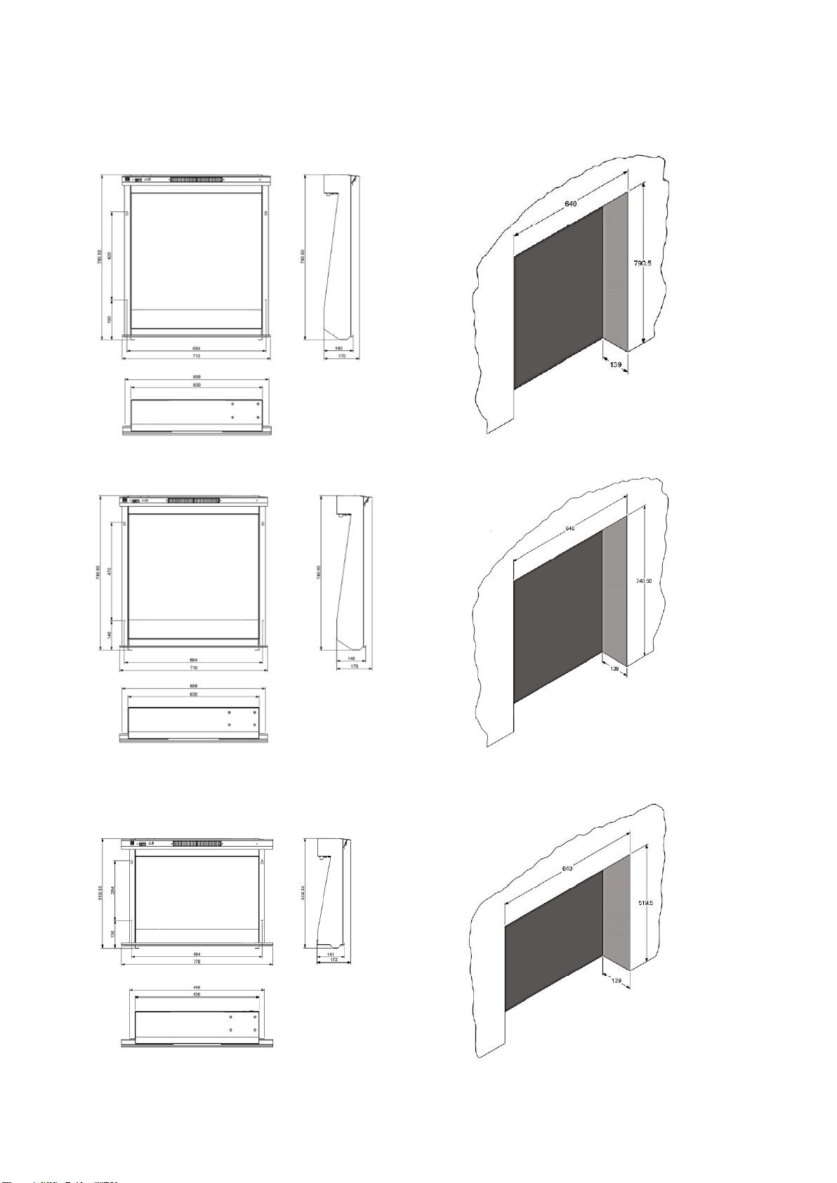
Appliance Dimensions Minimum opening sizes
1640 Standard Fire 1640 Standard
1640-50 Fire 1640-50 Fire
1640 Widescreen Fire 1640 Widescreen Fire
200701_1 Page 4
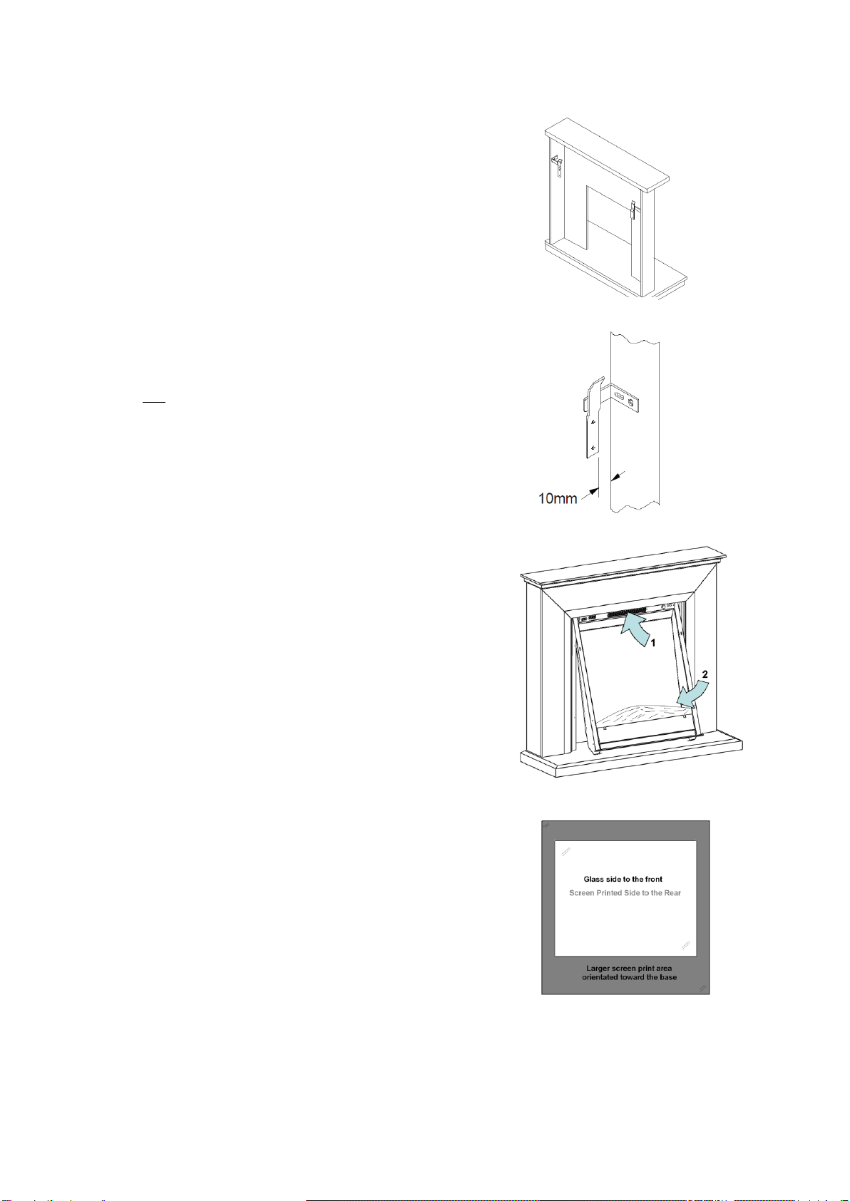
Installing the Mantel
1. Screw the mantel brackets (C) to the inside of each leg using the four 5/8”
screws (D) provided, making sure that they are flush with the rear of the leg.
The mantel brackets need to be mounted approximately 100mm from the
top of the mantel legs. This may differ slightly depending on the style of
mantel you have purchased. See Fig1
2. Position the mantel in the centre of the hearth, lightly marking the wall either
side of the legs. Measure in from this point, the thickness of the mantel leg
plus 10mm and mark again. See Fig 2
3. Ensure the mantel brackets (C) halfway between the two folds on the wall
brackets (C)
4. Lift the mantel off the hearth and fix the wall brackets (C) using suitable
fixings dependant on the type of wall material
5. Lift the mantel onto the wall brackets. If more tension is required take the
mantel off the wall and adjust using the slots on the mantel brackets.
6. N.B Should a defect be discovered and in the event of a suite being
permanently fixed to the wall, thus denying access to the back, then the
householder will be responsible for any costs incurred
Fitting the Fire unit (B) to the Suite (A) –if not supplied
fitted.
Caution: The manufacturer recommends two people for removal and installation
of this glass panel. Always use caution when handling glass, Failure to do so
could result in injury or property damage.
1 –It is recommended that two people are present to complete this next step,
With the fire laid on it back, remove the four screws in glass top bracket this
allows the top bracket to be removed and gives access to the glass panel (See
Page 2, Part B) carefully remove the glass panel by raising the top edge and
pulling towards the top of the fire (care must be taken to avoid damage to the
glass panel during this step), place the glass panel in a clean safe area.
2 - With the suite (A) in position, offer up the fire unit (B) to the suite opening
(Fig.3), inserting the top of the fire first and then swinging in the bottom of the fire
(ensure that during this step the fire is supported at the bottom at all times to
prevent scratching to the top of the Hearth)
Fig.3
3 –Using two of the four screws supplied (F) fit the screws through the top two fire mounting points (See Page 2, Part A and
B).
4 –Ensure the top two screws are adequately tightened and secure the fire using the
two bottom screws. (See Page 2, Part A and B)
5 –It is recommended that two people are present to complete this next step, place
the glass panel in the glass lower fixing bracket (See Page 2, Part B) ensuring that
the screen printed surface of the glass panel is facing towards the fire and the thicker
band of screen print is at the bottom (Fig. 4). With the glass panel in position offer up
the Glass top Bracket to the face of the heater and using the four 3/8” screws
removed in step 1 secure the Glass top bracket to the fire unit.
6 - The installation is now complete.
Fig. 4
Fig. 1
Fig. 2

200701_1 Page 5
1. Operating the Appliance:
1.1 The user controls on appliance are located at the upper left of the appliance.
1.2 Turning on the appliance with the main power switch to “—“position. A long beep will be heard.
1.3 Press “LIGHTS ON / OFF” to turn on or turn off the flame effect.
2. Operating by remote
1.1 The communication between the remote and appliance will already be established. Please read page 6 - 1.13 to
set it up if you can’t operate the appliance with the remote.
1.2 Turn on / off
1.2.1 Press to turn on the flame effect.
1.2.2 Press to turn off all the functions under the normal mode including flame effect and heater fan.
1.2.3 Press to turn off the flame effect under daily and weekly timer mode.
1.3 Flame effect
1.3.1 Press to enter the flame effect adjustment screen.
1.3.2 Press the ‘←’ and ‘→’ button to select the 3 colours of flame effect.
1.3.3 Press the ‘+’ and ‘-’button to to select the 5 brightness of flame effect.
1.4 Mood light (if applicable)
1.4.1 Press to enter the mood light adjustment screen.
1.4.2 Press the ‘←’ and ‘→’ button to cycle through the 13 colours of mood light or
a colour-cycle mode (setting 14)
1.4.3 Press the ‘+’ and ‘-’button to select the 5 brightness of mood light and OFF
settings.

200701_1 Page 6
1.5 Normal mode
1.5.1 Normal control mode is factory set. Or press button until the logo
shows up at the upper right corner of the screen.
1.5.2 Press the ‘+’ and ‘-’button to adjust the temperature setting from 17℃to
25℃(increments of 2℃)
1.5.3 Press button to turn on / off heat, ON、OFF will show at the
lower right corner of the screen. It is normal for the fan heater to stop running
for periods of time. This happens because the room temperature is at or
above the temperature set on the remote control.
The heater indicator will be turned off after 10s if you have the flame ON. The
heater indicator will stay ON if you use the heating function only.
1.5.4 Timer function
⚫This setting is only for normal mode. It allows the appliance to be returned to Standby after a set period of time.
⚫Press to cycle through the settings from Off and 0.5 hours to 9 hours. The timer logo and time will show on the
screen.
1.6 Low Battery
The battery symbol will flash on the screen when the remote’s batteries need replacing. Battery replacement is
recommended after 1 year. The batteries are 1.5V alkaline AA x 2.
The heater can be automatically run by using daily timer and weekly timer on the remote.
1.7 Weekly timer / daily timer / comfortable temperature and unit setting
1.7.1 Hold the button for 3 seconds to enter the setting screen.
1.7.2 Press the ‘←’ and ‘→’ button to choose what you want to select. The selected
character will be highlighted
●Press the ‘+’ and ‘-’ button to adjust the number.
●Time: 24-hour system
●Select your comfortable temperature from 15-25℃.
●Temperature unit: ℃、℉
1.8 Daily timer mode
1.8.1 Has the following preset heating periods, which can be altered if desired
06:00 until 8:30
17:00 until 22:00
1.8.2 Press until shows at the upper right corner of the screen, then enter the
daily timer heating mode.
1.8.3 Hold the button for 8 seconds to enter the daily heating setting.
⚫Max 3 timed heating periods per day.
⚫Press ‘←’ or ‘→’ to choose hour or minute, press ‘+’ or ‘-’to set the time.
⚫Minute setting increases / decreases by 15min per press.
⚫Press the ← or →to move to the next line or time setting on the current line, press
the →on the last line to return to the first time setting line.
⚫Hold for 3 seconds or wait for 8 seconds to save and exit the heating time
period setting.
1.8.4 Adjusting the temperature setting
⚫Press the ‘+’ or ‘-’ button to increase or decrease the temperature setting on the basis of your comfort temperature
setting.
⚫ECO means 2℃lower than your comfortable temperature setting, ECO- means 4℃lower, COMF+ means 2℃
higher, COMF++ means 4℃higher.

200701_1 Page 7
1.9 Weekly timer mode
1.9.1 The following preset heating periods can be altered if desired.
From Monday to Friday
06:00 until 08:30
17:00 until 22:00
From Saturday to Sunday
06:30 until 9:30
11:00 until 13:00
17:00 until 22:00
1.9.2 Press until shows at the upper right corner of the screen, then enter the week
heating mode.
1.9.3 Hold buttong for 8 seconds to enter the weekly timer heating mode setting.
⚫Press ‘←’ or ‘→’ to move the cursor (a flashing underline), press the button in the corresponding week
position to select (the character is highlighted) or cancel (the character is displayed normally) the current setting.
Several time periods can be selected together.
⚫Press the ‘→’ button to move the cursor to the time period setting area. Press ‘←’
or ‘→’ to choose hour or minute, press ‘+’ or ‘-’to set the number.
⚫Max 3 heating periods for a day.
⚫Minute will increase / decrease by 15mins per press.
⚫Press the ‘←’ or ‘→ to move to the next line or time setting on the current line,
press the →on the last line to return to the first time setting line
⚫Hold 3s or wait for 8s to save and exit the heating time period setting.
◼Advance mode
⚫Under the daily and week timer mode Pressing
⚫Will turn the heater on or off
◼Window open detection
⚫When the transmitter detects a rapid drop in room temperature, it will be judged as a
window open, the warning icon will be displayed and the heater will be turned off
automatically. After the indoor temperature has risen or by manual intervention (by
operating remote control), the heater will return to its normal working state.
1.10 Pairing the handset to the appliance
1.10.1 The below operation should be carried out before programming, when changing to a new remote or in the event
the appliance cannot be controlled by the remote:
⚫Hold the reset button on the appliance for 3 seconds (pen point may needed) until you hear 3 short beeps from the
unit, release the button.
⚫Press the button on the remote, the programming is finished when you hear 1 long
beep from the appliance.
1.10.2 Resetting the remote control is necessary if the appliance operates incorrectly or does not
respond when operated.
⚫Open the back cover of the remote control.
⚫Press the Reset button.
⚫Follow the programming steps.
Note: When the heater is turned on there will be a brief period (aprox 6 secs) where the heater will blow cold air.
This is to clear the elements of any debris (Dust, Hair etc) that may have collected on the elements. Similarly once
the heater is switched off the fan will blow cold air through the elements ensuring that the elements are cooled
before turning off the fan

200701_1 Page 8
Safety Thermal Cut-out and Thermal Link:
This appliance is fitted with an Electric Safety Control (E.S.). This is a safety device, which switches off the fire if, for any
reasons, the appliance overheats. The E.S. Control can only be re-set after the appliance has cooled down, in Order to re-
set the E.S. Control, proceed as follows:
•Switch off the appliance. Unplug at wall socket and leave for approximately 5-10 minutes.
•Plug in switch on appliance and the E.S. Control will re-set.
Ensure that the appliance is functioning correctly. If the E.S. Control switches off again it is advisable to have the appliance
checked by a competent electrician.
CAUTION: In order to avoid a hazard due to inadvertent resetting of the thermal cut out, this appliance must not be
supplied through an external switching device, such as a timer, or connected to a circuit that is regularly switched on and off
by the utility.
Maintenance:
WARNING: - Before undertaking any maintenance or cleaning, ensure appliance is disconnected from mains
supply.
Only competent persons should service / repair appliance.
WARNING: There are no internal user serviceable parts, i.e. bulbs, in this product. Under no circumstance should
access be gained to the internal parts other than by a suitably qualified person.
Please note: - If the supply cord on this appliance is damaged it must be replaced by the manufacturer, Authorised Service
Agent, or a qualified person to avoid hazard.
Care
Warning: Before undertaking any maintenance or cleaning disconnect appliance from main supply. Only competent persons
should service / repair appliances.
General Suite Care –not glass
To maintain the appearance of you new suite we recommend that it is dusted using a lint free cloth. NEVER use any form of
abrasives or a DAMP cloth on the surround. The area around the fire should be kept free of any materials such as lint or
house dust (i.e. animal hair/ carpet fibres) that could be drawn into the internal workings of the appliance and hence affect
the performance. We recommend that you clean around the fan grille housing at regular intervals. This can be done using
standard vacuum cleaner and suitable attachment.
Glass Care
Caution: The manufacturer recommends two people for removal and installation of this glass panel. Always use caution
when handling glass, Failure to do so could result in injury or property damage.
Periodically it may be necessary to remove the glass screen for cleaning. This is achieved by first disconnecting the
appliance from the mains supply and then removing the four screws securing the glass top bracket to the heater box, this will
release the glass top bracket. Important: Ensure that the glass panel is supported during removal as it may swing out from
the top when the glass top racket is removed. With the glass top bracket removed, lift the glass panel upwards and towards
to remove the panel from the fire. Place in a clean, soft, safe location for cleaning.
When cleaning the glass panels use a slightly damp cloth. Do not use washing powders or any other substance containing
abrasives since these substances scratch glass. Refitting is the reversal of this procedure.
Electric Fire Guarantee
Be Modern Ltd (the ‘Company’) provide a twelve month guarantee in respect of electric fire (the ‘Product’) ranges.
1. The twelve month Guarantee applies to:
•All ‘Products’ in the ranges manufactured by the ‘Company’ (but subject to exceptions below); where
•The ‘Product’ has been purchased and installed within the UK and in respect of
•The initial installation; and in favour of
•The original Purchaser
2. Proof of purchase must be retained by the Purchaser
3. The twelve month Guarantee does not apply to :
•Damage or inferior workmanship practices while the ‘Product’ is being installed
•Damage caused by the mis-use of the ‘Product’ or where normal standards of care and use have not been complied
with.
•Damage through a malfunction or an inadequately installed electric fire.
•Damage or defects due to, mis-use, accident or unauthorised alterations. During the twelve month after the ‘Product’
has been supplied, the Guarantee covers the making good (whether by repair or replacement at the company’s option)
of defects arising from defective manufacture of materials of ‘Product’ covered in paragraph (1), all at no cost to the
Purchaser. This Guarantee does not affect your statutory rights
On requiring service contact the retailer who supplied your product who will assist you and advise you as necessary.
Be Modern Ltd, Customer Services
Tel (0191) 430 0901-Fax (0191) 430 9522
200701_1 Page 9
Control PCB
Remote Control Receiver
Remote Control Transmitter
Frequency: ASK/OOK 433.92MHZ
Maximum transmit power: 10mW
Hardware:RF290A-TX-V1.3
Software: RF290A_C_V0.6.0.hex
Environment
Meaning of crossed –out wheeled dustbin:
Electrical appliances should not be disposed as unsorted municipal waste.
Separate collection facilities should be used in the disposal of electrical
appliances. Contact your local government for the information about the
available collection systems. If electrical appliances are disposed of in landfills
or dumps, hazardous substances can leak into the groundwater and get into
the food chain, damaging your health and well-being. When old appliances are
replaced by the new ones, it is a legal obligation for the retailer to take back the
old appliance for disposals at least free of charge.
This fire complies with the Safety Standards EN 60335-1 and EN 60335-2-30
which covers the essential requirements of the Low Voltage Directive
2014/35/EU and the EMC standards EN 55014-1; EN 55014-2; EN 61000-3-2
and EN 61000-3-3 which covers the essential requirements of the European
Electro Magnetic Compatibility 2014/30/EU, and the RED standards
EN300220-2, EN301489-1, EN301489-3 and EN6247 which covers the
essential requirements of the European Radio Equipment Directive
2014/53/EU.
This fire complies with the Safety Standards BS 60335-1 and BS 60335-2-30
which covers the essential requirements of the Electrical Equipment (Safety)
Regulations 2016 and the EMC standards BS 55014-1; BS 55014-2; BS 61000-3-
2 and BS 61000-3-3 which covers the essential requirements of the Electro
Magnetic Compatibility Regulations 2016, and the RED standards BS 300220-2,
BS 301489-1, BS 301489-3 and BS 6247 which covers the essential requirements
of the Radio Equipment Regulations 2017.
RoHS stands for Restriction of Hazardous Substances, and impacts the entire
electronics industry and many electrical products as well. The Restrictions of
the Use of Certain Hazardous Substances in Electrical and Electronic
Equipment Regulations 2012, originated in the European Union in 2002 and
restricts the use of six hazardous materials found in electrical and electronic
products. All applicable products in the EU and UK market since July 1, 2006
must pass RoHS compliance.
Hardware:
RC01-040A06
Software: 20171110
Hardware: RF290B V1.2

200701_1 Page 10
L 193/88
Official Journal of the European Union
Table 2
Information requirements for electric local space heaters
Model identifier(s):
1640 / 1640-50 / 1640-50 Portrait
Item
Symbol
Value
Unit
Item
Unit
Heat Output
Type of heat input, for electric storage local space
heaters only (select one)
Nominal heat
output
P nom
2.0
kW
manual heat charge control, with integrated
thermostat
[yes/no]
Minimum heat
output (indicative)
P min
1.0
kW
manual heat charge control with room and/or
outdoor temperature feedback
[yes/no]
Maximum
continuous heat
output
P max,
c
2.0
kW
electronic heat charge control with room
and/or outdoor temperature feedback
[yes/no]
Auxiliary electricity consumption
fan assisted heat output
[yes/no]
At nominal heat
output
el max
0.0125
kW
Type of heat output/room temperature control (select
one)
At minimum heat
output
el min
0.012
kW
Single stage heat output and no room
temperature control
[yes/no]
In standby mode
el SB
0.00048
kW
Two or more manual stages, no room
temperature control
[yes/no]
with mechanic thermostat room temperature
control
[yes/no]
with electronic room temperature control
electronic room temperature control plus day
timer
[yes/no]
electronic room temperature control plus
week timer
[yes/no]
Other control options (multiple selections possible)
room temperature control, with presence
detection
[yes/no]
room temperature control, with open window
detection
[yes/no]
with distance control option
[yes/no]
with adaptive start control
[yes/no]
with working time limitation
[yes/no]
with black bulb sensor
[yes/no]
Contact details
Name and address of the manufacturer or its authorised representative.
Be Modern Ltd, 19-34 Bedesway, Bede Industrial Estate, Jarrow, NE34 3BE
This manual suits for next models
1
Table of contents
Other bemodern Electric Heater manuals

bemodern
bemodern 1434 User manual

bemodern
bemodern 1174 User manual

bemodern
bemodern BM06 Operating instructions

bemodern
bemodern BM06 Operating instructions

bemodern
bemodern 1471 User manual

bemodern
bemodern 1174 Installation instructions

bemodern
bemodern Elec BM06 Operating instructions

bemodern
bemodern 1434 User manual

bemodern
bemodern 1122 User manual


