Makita BST220 Manual

Models No.
Description
PRODUCT
CONCEPT AND MAIN APPLICATIONS
Specification
Standard equipment
Optional accessories
P 1 / 9
Note: The standard equipment for the tool shown above may differ by country.
BST220, BST221
BST220
Cordless Stapler
Model BST220/ BST221 has been developed as cordless stapler with
14.4V/ 18V Li-ion battery.
Machined aluminum magazine provides precision and durability to ensure
smooth staple loading and feeding, also allowing for the use of commercial
staples.
The other features are as follows:
Rubberized soft grip
Hook
Easy-to-repair construction
Safety goggle .................. 1
Hook ................................ 1
10mm width Staples: length 10mm (3/8"), 13mm (1/2"), 16mm (5/8"), 19mm (3/4"), 22mm (7/8")
Battery chargers DC18RA, DC24SA, DC24SC
Li-ion Batteries BL1415, BL1815
L
H
W
Dimensions: mm (")
Width (W)
Height (H)
Length (L) 251 (9-7/8)
BST221BST220
247 (9-3/4)
251 (9-7/8)247 (9-3/4)
91 (3-5/8)
212 (8-3/8)
T
ECHNICAL INFORMATION
Model No.
Specifications
Net weight: kg (lbs)
Rubberized soft grip
Driving mechanism
Magazine
capacity: pcs.
Material of Magazine
pcs. per sheet
Maximum 98
Aluminum
Depth control
Hook
Staple
Battery
Dimensions: mm (")
Length
Width
Height
BST220 / BST221
10
10, 13, 16, 19, 22
(3/8, 1/2, 5/8, 3/4, 7/8)
84 a sheet
14.4Voltage: V 18
Yes
Trigger Single
Yes
Yes
2.3 (5.1)2.2 (4.9)
91 (3-5/8)
212 (8-3/8)
Gauge: mm (")
Length: mm (")
0.6x1.2 (1/32x1/16)
Width: mm
Remaining staple view window Yes
Spring drive
3.0
Capacity: Ah
Li-ion
Cell
22 (with DC18RA)
Charging time: min
Contact arm Yes

P 2/ 9
[2] LUBRICATION
[3] FASTENING TORQUE TO BOLTS AND SCREWS
Apply Makita grease N. No.2 to the portions designated with the black triangle to protect parts and product from unusual
abrasion.
When removing Guide bolt, be sure to apply ThreeBond 1303B / Loctite 272 to the thread before assembling.
M4x14 Hex. socket head bolts mainly for Driver guide and Magazine complete.....2.0 up to 3.0 N.m.
M5x18 Hex. socket head bolts mainly for Driver guide and Holder..........................4.9 up to 7.4 N.m.
M4x4 Pan head screw mainly for Adjuster base.........................................................0.6 up to 1.0 N.m.
[1] NECESSARY REPAIRING TOOLS
CAUTION: Remove Battery and Staple for safety before repair/ maintenance.
Repair
1R228
1R254
1R220
1/4" Hex. shank bit for M4
1R229 1/4" Hex. shank bit for M5
1R230 1/4" Hex. shank bit for M6
Torque wrench shaft 2-6N.m
Ratchet head 9.5
1R222 Socket Adapter Tightening Hex socket head bolts to the specific torque
Tightening Hex socket head bolts
DescriptionCode No. Use for
Fig. 1 Makita grease N. No.2
Thread of Guide bolt
(Apply adhesive.)

P 3/ 9
[4]-2. Disassembling Motor, Switch, Terminal
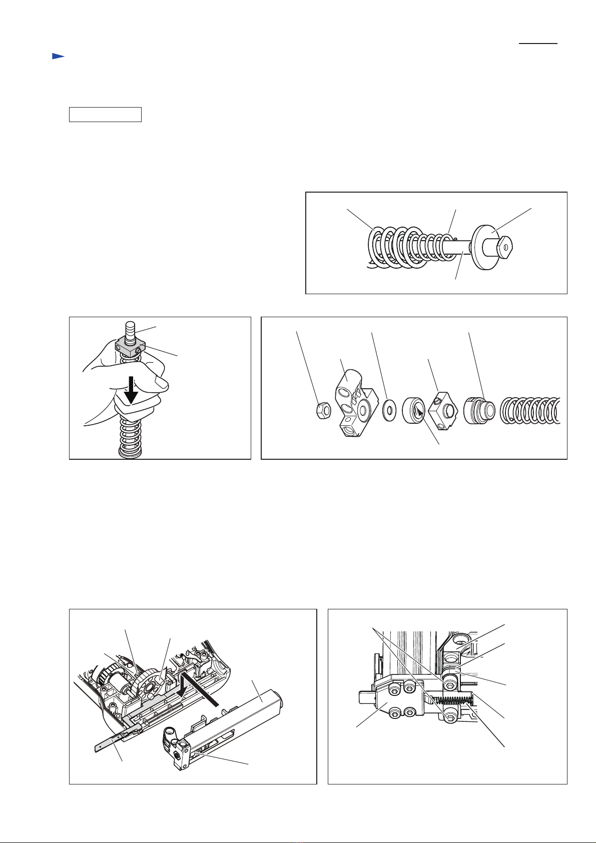
1) Remove 4x18 Tapping screws (4pcs.) and Front cover. (Fig. 2)
2) Slide Upper plate out of the grooves, then pull out Pin 4 for connecting Driver and Hammer. (Fig. 3)
Driver can be replaced.
3) Take the disassembling step in reverse. Face the hole of Driver to the upper side.
The chamfered corner of Driver is allowed to face either right or left side. (Fig. 3)
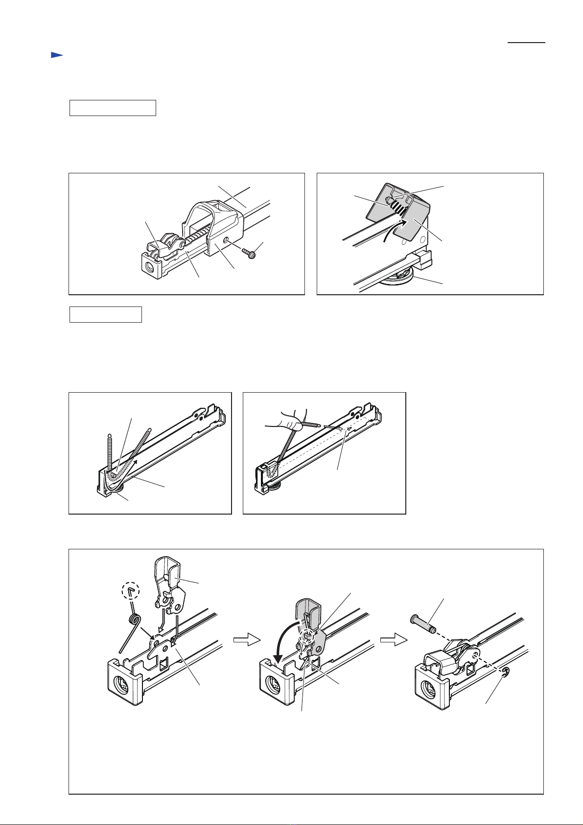
1) Remove Front cover, 4x18 Tapping screws (4pcs.), Upper plate, Pin 4 and Driver.
2) Remove Compression spring 4. (Fig. 8)
3) When Hammer is not located at the lowest position (i.e., the left illustration of Fig. 4);
1. Install Battery.
2. Pull Trigger in a blink and release it repeatedly until Hammer reaches the lowest position. (the right illustration of
Fig.4)
The pressure of Compression springs is now disappeared. Remove Battery.
4) Remove 4x18 Tapping screws (6pcs.), M4x10 Pan head screws (2pcs.), M4x35 Pan head screws (2pcs.) and Housing R
while holding Trigger to prevent popping out. (Fig. 5) Switch and Terminal can be replaced.
5) Remove Spur gear 55 complete, and then lever up Spur gear 7 complete with slotted screwdriver. (Fig. 6)
Internal gear 69, DC motor and their linked parts come with Spur gear 7 complete.
[4] DISASSEMBLY/ ASSEMBLY
[4]-1. Replacing Driver
Repair
Fig. 2
4x18 Tapping
screws (4pcs.)
Front cover
Driver
Upper plate
Fig. 4 Fig. 5
Fig. 3
chamfered
corner
hole
Pin 4
Upper side
Lower side
Upper side
Hammer
M4x35 Pan
head screws
(2pcs.)
4x18
Tapping
screws
(6pcs.)
M4x10 Pan head screws (2pcs.)
Lower side
Note: In the event of failure on Motor and Switch, Compression springs
in Driving section remain compressed.
Consequently, DC motor can not be removed due to the pressure.
Therefore, take the following step while holding the around of Trigger
with cloth to prevent popping out.
(Be careful not to pinch your hand between Hammer and Cushion.)
1. Insert slotted screwdriver between the gear teeth of Spur gear 7
complete.
2. Revolve Spur gear 7 complete by moving a gear tooth to the direction
designated in white arrow with the slotted screwdriver.
Fig. 6
Spur gear 7 complete
Spur gear 7
complete
slotted
screwdriver
Fig. 7
Internal gear 69, DC motor
and their linked parts

P 4/ 9
1) Remove Housing R. (Refer to previous page.)
2) Remove Compression spring 4. (Fig. 8)
3) Remove Fix plate and 4x18 Tapping screws (2pcs.) (Fig. 9)
4) Remove Safety lever guide and M4x6 Hex. socket head bolts (2pcs.), then loosen
M5x18 Hex. socket head screws (2pcs.) with Hex wrench 5 and 1R230. (Fig. 10)
5) Remove Magazine section.
6) Remove Guide plate, Hammer driving section and Safety cover. (Fig. 11)
7) Remove Slide plate from Housing L. (Fig. 12)
8) Remove Hammer by pulling out Pin 4 from Driver lock. (Fig. 13)
9) While holding Holder portion by gloved hand as illustrated in Fig. 14 (or clamping in vise), loosen Guide bolt by
hooking the flats and turning counterclockwise by monkey wrenches. When Guide bolt is separated,
Compression springs is slightly released.
10) Cushion etc. held in the gloved hand are removed as illustrated in Fig. 17 of next page.
[4] DISASSEMBLY/ ASSEMBLY
[4]-3. Hammer, Cushion
Repair
Fig. 9 Fig. 10
Fig. 11 Fig. 12
Fig. 13 Fig. 14
Fig. 8
4x18 Tapping screw (2pcs.)
Fix plate
Compression
spring 4
Safety lever guide
Magazine section
Slide plate
Hammer driving
section
Guide plate
Safety lever
M5x18 Hex. socket
head bolt (2pcs.)
M4x6 Hex. socket
head bolt (2pcs.)
Pin 4
Driver lock
Hammer flats of
head portion
of Guide bolt
DISASSEMBLING

P 5/ 9
1) As illustrated in Fig. 15, set Compression springs 13 and 9 in place on Guide bolt after installing Flat washer 8.
2) Pass Guide bolt through Driver lock. While pressing the compression springs onto worktable, mount the following parts
on Compression spring 13.
- M6 Hex. nut
- Holder
- Flat washer 6
- Cushion
- Driver lock
- Spring holder
Note: 1. When loosening Guide bolt, apply ThreeBond
1303B or Loctite 272 to the thread of Guide bolt.
2. Fit the inner lip of Cushion into the groove on
Guide bolt completely, or M6 Hex. nut will not
be installed firmly to the thread of Guide bolt.
3) Move Spur gear 55 complete until the roller portion is placed as illustrated in Fig. 18, and secure Pin 10 to Housing L by
tightening 4x18 Tapping screw.
4) Mount Safety lever on Housing L.
5) Cover Hammer driving section with Guide plate, and install them into Housing L. (Fig. 18)
6) Check that Safety lever can be slid smoothly.
7) Secure both ends of Hammer driving section with 4x18 Tapping screws (2pcs.) and Fix plate. (Fig. 9)
8) Move Safety lever to the forward position to the full. And then put Set plate between Holder and Driver guide complete.
Fasten them to Magazine section by tightening M5x18 Hex. socket head bolts (2pcs.). (Fig. 19)
9) Secure Safety lever guide by tightening M4x6 Hex. socket head bolts (2pcs.). (Fig. 10)
10) Set Compression spring 4 in place. (Fig. 19)
[4] DISASSEMBLY/ ASSEMBLY
[4]-3. Hammer, Cushion (cont.)
Repair
Fig. 16
Fig. 18 Fig. 19
thread of Guide bolt
Driver lock
ASSEMBLING
Hammer driving section
Safety lever guide
Spring base
Compression
spring 4
Holder
M5x18 Hex. socket head bolt (2pcs.)
Set plate
Driver guide
complete
Guide plate
Roller portion of Spur gear 55 complete
has to be placed as illustrated.
Safety lever
4x18 Tapping
screw
Fig. 17
Fig. 15
M6 Hex. nut
Holder
inner lip of Cushion
Compression spring 13 Compression spring 9
Guide bolt
Flat washer 8
Flat washer 6 Spring holder
Driver lock
Pin 10

P 6/ 9
1) Hook Torsion spring 3 with the protrusion of Housing L. (Fig. 20)
2) Attach the short end to the wall of Housing L. (Fig. 21)
3) After inserting Switch to twin protrusion, set Trigger and the linked parts in place as illustrated in Fig. 22.
twin protrusion for
Switch installation
Protrusion for
Torsion spring 3
long end
Housing L
short end
[4] DISASSEMBLY/ ASSEMBLY
[4]-4. Switch, Trigger
Repair
ASSEMBLING
Fig. 22
Release plate
long tail of Torsion spring 3
Switch button
Pin 3
Put the bend portion of Release plate between
Switch button and wide width of Leaf spring.
Put the hook portion of Leaf spring
along the inside of Trigger.
Put the long tail of Torsion spring 3 to the
upward of narrow width of Leaf spring.
Fig. 20
twin protrusion for Switch installation
Switch
Leaf spring Trigger
shape of Leaf spring
Apply a little amount of
Makita grease N No.2 to
the contact area of
Release plate and Leaf
spring (designated by black).
The short end of Torsion
spring 3 has to be behind
the wall of Housing L.
Fig. 21
wide width
hook portion
narrow width
Torsion spring 3

P 7/ 9
1) Remove DC motor section in accordance with the clause [4]-2.
2) Disassemble Gear section as illustrated in Fig. 23.
3) Remove Leaf spring from Housing L. (Fig. 24)
4) Cover the pins of Spur gear 7 complete with Internal gear 69. Refer to the direction of Internal gear 69. (Fig. 23)
5) After inserting the pins of Spur gear 7 complete into Spur gears 27 (3pcs.), mount Flat washer 12 on Internal gear 69.
6) Install the assembled parts (Flat washer 12, Internal gear 69, Spur gear 27 (3pcs.) and Spur gear 7 complete) into
Housing L so that the large protrusion of Internal gear 69 can be seen. (Fig. 25)
7) Insert Leaf spring into Housing L. (Inserting Leaf spring into Housing L before installation of the assembled parts
causes difficulty.)
8) Plate and Spur gear 55 complete have to be fixed as illustrated in Fig. 26. Refer to their directions.
DC motor
Leaf spring large protrusion of Internal gear 69
(small protrusion)
Sleeve 5 Flat washer 10
Plate Spur gear 55 complete
(To Housing L: Refer to Fig. 18)
Flat washer 12
Internal gear 69
Note: Apply a little amount of Makita grease N No.2 to the inner periphery.
[4] DISASSEMBLY/ ASSEMBLY
[4]-5. Replacing Gear section
Repair
Fig. 23
Fig. 24 Fig. 24
Fig. 26
Spur gear 27 (3pcs.)
Flat washer 10
Plane bearing 10
Spur gear 7 complete
Note: Apply a little amount of Makita grease
N No.2 to the pins.
4x18 Tapping screw
Pin10

P 8/ 9
1) Remove M4x10 Pan head screw, and then pull out Sub magazine from Main magazine.
2) Pivot Pusher and Separate it from Tension spring 3 and Sub magazine.
3) Remove Stop ring E-3 from Pin 4. Lever portion can be removed.
Sub magazine
DISASSEMBLING
Main magazine
End cap
Pusher
Adjuster
Adjuster side of
Sub magazine
Lever side of
Sub magazine
notch of Pusher
Tension
spring 3
M4x10
Pan head
screw
[4] DISASSEMBLY/ ASSEMBLY
[4]-6. Magazine section
Repair
Fig. 27
Fig. 29
Fig. 31
Fig. 30
Fig. 28
1) Pass Tension spring 3 between cylinder portion and bottom of Sub magazine. (Fig. 29)
2) Hook the spring end on Adjuster side with the notch of Pusher . (Fig. 28)
3) Pick up the other spring end using Pincette. And hook the spring end with the hook on the bottom of Sub magazine as
illustrated in Fig. 30.
4) As for Lever portion, assembling the components in accordance with the way illustrated in Fig. 31.
ASSEMBLING
bottom of
Sub magazine
Adjuster
hook on the bottom
of Sub magazine
cylinder portion of Sub magazine
for hooking Tension spring 3
Lever
straight end
Torsion spring
5
Lever
Pin 4
Stop ring E-3
Sub magazine hook of
Sub magazine
protrusion of
Lever
Straight tail attached to the bottom of
Sub magazine
bend end
Attach the bend end of Torsion spring 5
to the inside of Lever. Then insert Lever
and Torsion spring 5 into Sub magazine.
Move Lever vertical to Sub magazine,
and hook the protrusion of Lever with
the hook of Sub magazine while
compressing Torsion spring 5.
Secure Lever portion in place by
Stop ring E-3 and Pin 4.

P 9/ 9
Circuit diagram
Fig. D-1
Fig. D-2
Wiring diagram
red marking for distinction
to connect white lead wire
Color index of lead wires' sheath
Black
Red
White
DC Motor
Terminal
Do not put
Lead wires
on rib.
Face Lead wires to DC motor side
when connecting Terminal and Flag
connectors of the Lead wires.
Face Lead wires to Housing L side
when connecting Terminals of DC motor
and Flag connectors of the Lead wires.
Terminal
DC motor
Switch
Other manuals for BST220
6
This manual suits for next models
1
Table of contents
Other Makita Power Tools manuals

Makita
Makita DUP361 User manual

Makita
Makita 3620 User manual

Makita
Makita 3708 User manual

Makita
Makita DHG181ZJ User manual

Makita
Makita TW160DZ User manual

Makita
Makita BJN160 User manual

Makita
Makita RP1111C User manual

Makita
Makita 6911HD User manual

Makita
Makita 8406 User manual

Makita
Makita HR007G User manual

Makita
Makita DTW701 User manual

Makita
Makita HM1200 User manual

Makita
Makita BJS130Z User manual

Makita
Makita HM1242C User manual

Makita
Makita 3612C User manual

Makita
Makita LXJP02 User manual

Makita
Makita BJN160 User manual

Makita
Makita HM1213C User manual

Makita
Makita CG100DZXK User manual

Makita
Makita DUP180 User manual