Avdel 7265 User manual

Hydro-Pneumatic Power Tool
07265
07265
I n s t r u c t i o n M a n u a l
Pass onto user to read and keep for reference

AIR PRESSURE Minimum - Maximum 5 - 7 bar 70 - 100 lbf/in2
FREE AIR VOLUME REQUIRED @ 5.5 bar / 80 lbf/in23.5 litres .12 ft3
STROKE Minimum 26.2 mm 1.03 in
PULL FORCE @ 5 bar / 70 lbf/in215 kN 3350 lbf
CYCLE TIME Approximately 1.7 seconds
NOISE LEVEL Less than 70 dB(A)
PISTOL WEIGHT 3.1 kg 6.82 lb
TOTAL WEIGHT Pistol & Intensifier 37 kg 81.4 lb
VIBRATION Less than 2.5 m/s28 ft/s2
S P E C I F I C A T I O N S F O R 0 7 2 6 5 T O O L
■
■
■
■
■
■
■
■
■
■
■
■
■
■
■
■
■
■
■
■
■
■
■
■
■
AVDEL policy is one of continuous development. Specifications shown in this document may be subject to changes which
may be introduced after publication. For the latest information always consult Avdel.

S A F E T Y
I N T E N T O F U S E
P U T T I N G I N T O S E R V I C E
N O S E A S S E M B L I E S
S E R V I C I N G
P R I M I N G
F A U L T D I A G N O S I S
General 2
Specific to Type of Tool 3
General 4
07265 Tool Dimensions / Selection 4-5
Air Supply 6
Operating Procedure 6
Accessories 7-8
07265 Fitting/Servicing/Components 10-11
Regular Servicing - Service Kit 12
Maintenance 13-15
General Assembly & Parts List 16-21
Priming Oil Details 22
Priming Procedure 22
Fault Diagnosis Table 23
CO N T E N T S
1

SA F E T Y
2
This instruction manual must be read with particular attention to the following safety rules,
by any person installing, operating, or servicing this tool.
DO NOT USE OUTSIDE THE DESIGN INTENT.
DO NOT USE EQUIPMENT WITH THIS TOOL/MACHINE OTHER THAN THAT
RECOMMENDED AND SUPPLIED BY AVDEL.
ANY MODIFICATION UNDERTAKEN BY THE CUSTOMER TO THE TOOL/MACHINE,
NOSE ASSEMBLIES, ACCESSORIES OR ANY EQUIPMENT SUPPLIED BY AVDEL OR THEIR
REPRESENTATIVES, SHALL BE THE CUSTOMER'S ENTIRE RESPONSIBILITY. AVDEL WILL BE
PLEASED TO ADVISE UPON ANY PROPOSED MODIFICATION.
THE TOOL/MACHINE MUST BE MAINTAINED IN A SAFE WORKING CONDITION AT
ALL TIMES AND EXAMINED AT REGULAR INTERVALS FOR DAMAGE AND FUNCTION BY
TRAINED COMPETENT PERSONNEL. ANY DISMANTLING PROCEDURE SHALL BE
UNDERTAKEN ONLY BY PERSONNEL TRAINED IN AVDEL PROCEDURES. DO NOT DISMANTLE
THIS TOOL/MACHINE WITHOUT PRIOR REFERENCE TO THE MAINTENANCE INSTRUCTIONS.
CONTACT AVDEL WITH YOUR TRAINING REQUIREMENTS.
THE TOOL/MACHINE SHALL AT ALL TIMES BE OPERATED IN ACCORDANCE WITH
RELEVANT HEALTH AND SAFETY LEGISLATION. IN THE U.K. THE “HEALTH AND SAFETY AT
WORK ETC. ACT 1974” APPLIES. ANY QUESTION REGARDING THE CORRECT OPERATION
OF THE TOOL/MACHINE AND OPERATOR SAFETY SHOULD BE DIRECTED TO AVDEL.
THE PRECAUTIONS TO BE OBSERVED WHEN USING THIS TOOL/MACHINE MUST BE
EXPLAINED BY THE CUSTOMER TO ALL OPERATORS.
ALWAYS DISCONNECT THE AIRLINE FROM THE TOOL/MACHINE INLET BEFORE
ATTEMPTING TO ADJUST, FIT OR REMOVE A NOSE ASSEMBLY.
DO NOT OPERATE A TOOL/MACHINE THAT IS DIRECTED TOWARDS ANY PERSON(S).
ALWAYS ADOPT A FIRM FOOTING OR A STABLE POSITION BEFORE OPERATING THE
TOOL/MACHINE.
ENSURE THAT VENT HOLES DO NOT BECOME BLOCKED OR COVERED AND THAT
HOSES ARE ALWAYS IN GOOD CONDITION.

3
In addition to the general safety rules opposite, the following specific safety points must also
be observed:
THE OPERATING PRESSURE SHALL NOT EXCEED 7 BAR - 100 LBF/IN2.
DO NOT OPERATE THE TOOL WITHOUT FULL NOSE EQUIPMENT IN PLACE.
CARE SHALL BE TAKEN TO ENSURE THAT SPENT STEMS ARE NOT ALLOWED TO
CREATE A HAZARD.
THE TOOL MUST BE FITTED WITH AN UNDAMAGED PINTAIL DEFLECTOR OR STEM
CATCHER BEFORE OPERATING.
IF THE TOOL IS FITTED WITH A PINTAIL DEFLECTOR AND IS USED IN THE VERTICAL
NOSE DOWNWARD POSITION, THE PINTAIL DEFLECTOR SHOULD BE ROTATED UNTIL THE
APERTURE IS FACING AWAY FROM THE OPERATOR AND OTHER PERSON(S) WORKING IN
THE VICINITY.
WHEN USING THE TOOL, THE WEARING OF SAFETY GLASSES IS REQUIRED BOTH BY
THE OPERATOR AND OTHERS IN THE VICINITY TO PROTECT AGAINST RIVET EJECTION,
SHOULD A FASTENER BE PLACED ‘IN AIR’. WE RECOMMEND WEARING GLOVES IF THERE
ARE SHARP EDGES OR CORNERS ON THE APPLICATION.
TAKE CARE TO AVOID ENTANGLEMENT OF LOOSE CLOTHES, TIES, LONG HAIR,
CLEANING RAGS ETC. IN THE MOVING PARTS OF THE TOOL WHICH SHOULD BE KEPT DRY
AND CLEAN FOR BEST POSSIBLE GRIP.
WHEN CARRYING THE TOOL FROM PLACE TO PLACE KEEP HANDS AWAY FROM THE
TRIGGER/LEVER TO AVOID INADVERTENT START UP.
EXCESSIVE CONTACT WITH HYDRAULIC OIL SHOULD BE AVOIDED. TO MINIMIZE THE
POSSIBILITY OF RASHES, CARE SHOULD BE TAKEN TO WASH THOROUGHLY.

The hydro-pneumatic 07265 tool is designed to place Avdel breakstem rivets at high speed making it ideal for batch or flow-line
assembly in a wide variety of applications throughout all industries.
The 07265 is of the remote intensifier or split tool concept, (see page 5).
Pistol Grip type head fitted with a stem catcher is the standard tool for which a stem deflector is available (see details page 9). It is also
possible to order the base tool only (part number 07265-00300) which will not be fitted with a nose assembly.
4
IN T E N T O F U S E
Steel
Al. Alloy
Al. Alloy
Al. Alloy
Al. Alloy
Al. Alloy
Al. Alloy
Al. Alloy
Al. Alloy
Al. Alloy
Steel
St. Steel
Al. Alloy
Steel
St. Steel
Al. Alloy
Steel
St. Steel
St. Steel
Al. Alloy
Al. Alloy
Steel
Al. Alloy
Steel
Al. Alloy
Steel
AVEX
Snap Head
TLR
AVSEAL
MONOBOLT
Protruding Head
& 100˚ csk
*
The nose tip actually
remains the same, it is
the nose casing that is
longer.
See nose assemblies on
page 10 for details.
AVINOX BE61
AVTAINER
MAXLOK
Brazier Head
& 90˚ csk
HEMLOK
Protruding Head
3/16"
3/16"
1/4"
8mm
9mm
10mm
3/16"
1/4"
3/16"
3/8"
3/16"
1/4"
1/4"
07265-00030
07265-00008
07265-00010
07265-00040
07265-00045
07265-00041
07265-00046
07265-00042
07265-00047
07265-00012
07265-00012
07265-00012
07265-00014
07265-00014
07265-00014
07265-00016
07265-00016
07265-00016
07265-00036
07265-00006
07265-00001
07265-00001
07265-00002
07265-00002
07265-00004
07265-00004
07381-04800
07498-02000
07498-01100
07340-08000
07498-08800
07340-08100
07498-08900
07340-08200
07498-09000
07498-04700
07498-04700
07498-04700
07498-04600
07498-04600
07498-04600
07498-00500 *
07498-00500 *
07498-00500 *
07347-03700
07498-00700
07610-02000
07610-02000
07610-02100
07610-02100
07612-02000
07612-02000
07265 TOOL SELECTION
FASTENER NOSE (see drawing above for A & B)
MATERIAL/
DETAIL
ØCOMPLETE
TOOL PART Nº
NOSE ASSY
PART Nº
-
-
-
-
-
-
-
-
-
-
-
-
-
-
-
-
-
-
-
-
07265-02900
07265-02900
07265-02900
07265-02900
-
-
ADAPTOR
PART Nº
NAME &
HEAD
Standard
Standard
Standard
Standard
Extended
Standard
Extended
Standard
Extended
Standard
Standard
Standard
Standard
Standard
Standard
Extended *
Extended *
Extended *
Standard
Standard
Standard
Standard
Standard
Standard
Standard
Standard
.13
.16
.156
.22
.285
.22
.285
.22
.285
.16
.16
.16
.156
.156
.156
.156
.156
.156
.13
.16
.14
.14
.14
.14
.14
.14
A
(in)
2.4
2.4
3.6
3.9
3.9
3.9
3.9
3.9
3.9
2.4
2.4
2.4
2.4
2.4
2.4
3.9
3.9
3.9
2.4
7.4
2.0
2.0
2.1
2.1
2.4
2.4
B
(in)
3.3
4.1
4.0
5.6
7.2
5.6
7.2
5.6
7.2
4.1
4.1
4.1
4.0
4.0
4.0
4.0
4.0
4.0
3.3
4.1
3.6
3.6
3.6
3.6
3.6
3.6
A
(mm)
61
61
99
99
99
99
99
99
99
61
61
61
61
61
61
99
99
99
61
188
51
51
53
53
61
61
B
(mm)
NOSE TIP
TYPE

07265
B
A
6.5
160
1.35
34
5.15
130
500
19.7
400
15.75
25
0
9.85
5000
197
5
07265 - TOOL DIMENSIONS
Features include an on/off switch for a vacuum facility and an adjustable air restrictor to control the amount of vacuum according to
which fastener is being used.
Spent stems are collected in a stem catcher.
The vacuum is also used to retain fastener in the nose tip prior to its installation.
Dimensions shown in bold are millimetres.
Other dimensions are in inches.

O P E R A T I N G P R O C E D U R E
OPTION 1
Ensure that the correct nose equipment is fitted.
Connect the tool to the air supply.
Insert the fastener body squarely into the prepared hole of the
application.
Apply the tool to the protruding fastener stem.
Fully operate the trigger. The tool cycle will ensure the fastener
is placed.
Check that stems are projected into the stem catcher unit. If not
refer to the vacuum stem extraction valve paragraph on page
14 in the Maintainence section.
8
6
4
2
0
10
12
14
16
TAKE OFF POINT
FROM MAIN SUPPLY
STOP COCK
(USED DURING MAINTENANCE
OF FILTER/REGULATOR
OR LUBRICATION UNITS)
MAIN SUPPLY
DRAIN POINT
PRESSURE REGULATOR
AND FILTER
(DRAIN DAILY)
LUBRICATOR
3
M
E
T
R
E
S
M
A
X
I
M
U
M
07265
6
PU T T I N G I N T O S E R V I C E
A I R S U P P L Y
All tools are operated with compressed air at an optimum pressure of 5.5 bar. We recommend the use of pressure regulators and
automatic oiling/filtering systems on the main air supply. These should be fitted within 3 metres of the tool (see diagram below) to ensure
maximum tool life and minimum tool maintenance.
Air supply hoses should have a minimum working effective pressure rating of 150% of the maximum pressure produced in the system
or 10 bar, whichever is the highest. Air hoses should be oil resistant, have an abrasion resistant exterior and should be armoured where
operating conditions may result in hoses being damaged. All air hoses MUST have a minimum bore diameter of 6.4 millimetres or 1/4inch.
Read servicing daily details page 10.
■
■
■
■
■
■
■
■
■
■
■
■
OPTION 2
Ensure that the correct nose equipment is fitted.
Connect the tool to the air supply.
Insert the fastener stem into the nose of the tool.
Insert the tool with the fastener squarely into the prepared hole
of the application.
Fully operate the trigger. The tool cycle will ensure the fastener
is placed.
Check that stems are projected into the stem catcher unit. If not
refer to the vacuum stem extraction valve paragraph on page
14 in the Maintainence section.

PIN TAIL DEFLECTOR
Item numbers in bold refer to the general assembly and parts list
on pages 16 and 17.
To replace the stem catcher with a pin tail deflector remove
stem catcher end cap 38 and silencer 39.
Unscrew screws 36and remove stem catcher assembly together
with end cover 40.
Unscrew screws 15 and remove adaptor 14.
Push pin tail deflector onto the boss on stop cover 13.
7
Pin Tail Deflector
part nº 07220-00215
07265-09500 PARTS LIST
ITEM PART Nº DESCRIPTION QTY SPARES
107265-09501 RUBBER HANDLE 1 -
207265-09502 TUBE WITH HOOK 1 -
307265-09504 M5 BOLTS 2 -
407265-09503 HOLSTER 1 -
507265-09505 M5 NUTS 3 -
607265-09508 BASE 1 -
707265-09507 M5 BOLT 4 -
807265-09506 M5 BOLT 1 -
907265-09509 PLATE 1 -
A C C E S S O R I E S
Three different accessories are available:
HANDLING AND HOLSTER KIT
This kit enables an easier handling of the cabinet around the
workplace and allows the tool pistol to be stored in a convenient
position.
■
■
■
■
12
34
5
5
7
8
6
9
1
23
4
1
5
6
*14
*157*16
89
10
11 9
13
12
2
6
5
8
QUICK CONNECT KIT
This kit enables rapid connection of the handle and
hose to the cabinet.
107265-03206 NUT 4 -
207265-03269 CONNECTION 4 -
307265-03295 AIR HOSE EXTENSION 2 -
407265-09296 OIL HOSE EXTENSION 1 -
507265-03204 WASHER 4 -
607265-03205 SCREW 4 -
707265-03297 TRAY 1 -
807265-03258 NIPPLE 1 -
907265-03259 WASHER 2 -
10 07265-02056 QUICK FITTING NIPPLE 1 -
11 07265-02055 QUICK FITTING COUPLER 1 -
12 07265-03272 WASHER 2 -
13 07265-03221 CONNECTOR 2 -
*07265-03290 RUBBER RING 1 -
*07265-03291 SPACER WASHER 1 -
*07265-03292 CLAMP 1 -
ITEM PART Nº DESCRIPTION QTY SPARE
S
07265-01250 PARTS LIST
* These items are part of the Base Tool and are not part of the Quick
Connect kit.

9

10
It is essential that the correct nose assembly is fitted prior to operating the tool. By knowing your original complete tool part number
or the details of the fastener to be placed, you will be able to order a new complete nose assembly using the selection tables on page 8 .
NO S E A S S E M B L I E S
I M P O R T A N T
The air supply must be disconnected when fitting or removing nose assemblies unless specifically instructed otherwise.
FITTING INSTRUCTIONS FOR MAXLOK NOSE ASSEMBLIES
If the tool is fitted with end plug 07265-03015 (item 33 on pages 16 and 17) this will need to be removed.
Using appropriate spanners* unscrew end plug 33 from piston 16.
Screw end plug item 7 (see illlustration onpage 11) onto the tool piston and tighten using appropriate spanners*.
Screw Maxlok adaptor casing item 8 over the end plug 7 and into the handle of the tool.
Lightly coat the jaws with Moly Lithium grease.
Drop the jaws 3 into the chuck collet 2.
Drop spring guide 5 inti chuck collet 2, followed by spring 4 so that it locates around the spring guide.
Drop second spring guide 5 into chuck collet 2 so that it locates in spring 4.
Locate friction ring 6 on end plug 7.
Screw on previously assembled items 2,3,4 and 5 onto end plug 7.
Slide anvil 1 over chuck collet 2.
Secure anvil 1 by sliding nose retaining collar over anvil and screwing it onto adaptor casing 8.
■
■
■
■
■
■
■
■
■
■
■
FITTING INSTRUCTIONS
Lightly coat the jaws with Moly lithium grease.
Drop jaws 5 into jaw housing 4 or chuck collet 3, depending on whether you have a short or long nose assembly (see table opposite
for identification).
Insert jaw spreader 7 into jaw housing 4 (locating in the ‘V’ shape formed by the jaws) or insert front spring guide 6 into chuck
collet 3.
Locate buffer 8 on jaw spreader 7.
Locate spring 9 onto jaw spreader 7 or onto front spring guide 6.
On long nose assemblies, screw rear spring guide 10 into chuck collet 3.
Fit locking ring 11 onto the end plug of the tool.
Holding tool pointing down, screw on the assembled jaw housing or chuck collet onto the end plug and tighten with spanner.
Screw nose tip 1 into nose casing 2.
Place nose casing 2 over jaw housing 4 or chuck collet 3 and screw onto tool, tightening with spanner.
To fit Avtainer nose assembly, remove end plug 33 part number 07265-03015 from piston rod 16 and replace with adaptor part
number 07265-02900.
■
■
■
■
■
■
■
■
■
■
■
12 3 5 10 116 9
1 2 4 9115 87

11
1*9 235
*7
456
*8
* These items make up the Adaptor Kit, part number 07265-02900, and are not part of the Maxlok nose assembly.
SERVICING INSTRUCTIONS
Nose assemblies should serviced at weekly intervals.
Remove the complete nose assembly using the reverse procedure to the ‘Fitting instructions’.
Any worn or damaged part should be replaced by a new part.
Particularly check wear on jaws.
Ensure jaw spreader assembly tube 7 (where fitted) or front spring guide 6 is not distorted.
Check spring 9 is not distorted.
Assemble according to fitting instructions.
■
■
■
■
■
■
07265 NOSE ASSEMBLY COMPONENTS
This table lists the components which make up nose assemblies. Each nose assembly represents a unique assembly of components which
can be ordered individually. Component numbers refer to the illustration on the opposite page. We recommend some stock as items
will need regular replacement. Read the Nose Assemblies servicing instructions opposite carefully. All nose assemblies also include a
locking ring 11 part number 07340-00327 (see illustration opposite).
NOSE ASSY 1 2 3 56910
07340-08000 07340-08001 07498-00501 07498-00502 07497-03002 07498-00507 07500-02005 07498-00503
07340-08100 07340-08101 07498-00501 07498-00502 07497-03002 07498-00507 07500-02005 07498-00503
07340-08200 07340-08201 07498-00501 07498-00502 07497-03002 07498-00507 07500-02005 07498-00503
07498-00500 07497-03202 07498-00501 07498-00502 07497-03002* 07498-00507 07500-02005 07498-00503
07498-00700 ** 07498-00802 07498-00501 07498-00801 07220-02302 07498-00803 07500-02005 07498-00503
07498-01100 07498-01101 07498-00501 07498-00502 07498-03002* 07498-00507 07500-02005 07498-00503
07498-08800 07498-08801 07498-00501 e 07498-00502 07497-03002* 07498-00507 07500-02005 07498-00503
07498-08900 07498-08901 07498-00501 e 07498-00502 07497-03002* 07498-00507 07500-02005 07498-00503
07498-09000 07498-09001 07498-00501 e 07498-00502 07497-03002* 07498-00507 07500-02005 07498-00503
07498-00700 07498-00802 07498-00501 07498-00801 07220-02302 07498-00803 07500-02005 07498-00503
NOSE ASSY 1 2 4 5789
07498-02000 07605-00220 07340-00306 07498-04503 07498-04501* 07498-04900 07498-03003 07100-04003
07498-04600 07497-03202 07340-00306 07340-00304 07498-04501* 07498-04502 07498-03003 07100-04003
07498-04700 07498-03001 07340-00306 07498-04503 07498-04501* 07498-04900 07498-03003 07100-04003
07381-04800 07490-04401 07340-00306 07340-00304 07340-07502 07381-04801 07498-03003 07100-04003
07347-03700 07498-01401 07340-00306 07340-00304 07340-07502 07381-04801 07498-03003 07100-04003
07612-02000 07612-02001 07340-00306 07612-02003 07612-02002 07612-04502 07498-03003 07500-00418
There are normally two jaws:
Indicates three nose jaws
Indicates a long nose assembly
Indicates a nose assembly specifically for Avtainer fasteners and includes a side ejection adaptor, part number 07498-00900
*
e
**
MAXLOK NOSE ASSEMBLY COMPONENTS
NOSE ASSY 1 2 3 456*7*8*9
07610-02000 07610-02001 07610-02002 07610-02003 07610-02107 07220-02104 07610-02004 07265-02039 07265-02040 07265-02041
07610-02100 07610-02101 07610-02102 07610-02103 07610-02107 07610-02104 07610-02004 07265-02039 07265-02040 07265-02041
Regular servicing should be carried out and a comprehensive inspection performed annually or every 500000 cycles, whichever is
sooner.
I M P O R T A N T
The employer is responsible for ensuring that tool maintenance instructions are given to the appropriate personnel. The operator should
not be involved in maintenance or repair of the tool unless properly trained.
D A I L Y
Daily, before use or when first putting the tool into service, pour a few drops of clean, light lubricating oil into the air inlet of the
tool if no lubricator is fitted on air supply. If the tool is in continuous use, the air hose should be disconnected from the main air
supply and the tool lubricated every two to three hours.
Check for air leaks. If damaged, hoses and couplings should be replaced by new items.
If there is no filter on the pressure regulator, bleed the air line to clear it of accumulated dirt or water before connecting the air
hose to the tool. If there is a filter, drain it.
Check that the nose equipment is correct.
Check oil level in intensifier’s reservoir. If necessary top up with the prescribed priming oil.
W E E K L Y
Dismantle and clean the nose assembly with special attention to the jaws. Lubricate with Moly Lithium grease before assembling.
Check for oil leaks and air leaks in the air supply hose and fittings.
Grease can be ordered as a single item, the part number is shown in the service kit opposite.
12
SE R V I C I N G T H E T O O L
M O L Y L I T H I U M G R E A S E E P 3 7 5 3 S A F E T Y D A T A
FIRST AID
SKIN: As the grease is completely water resistant it is best
removed with an approved emulsifying skin cleaner.
INGESTION: Make the individual drink 30ml Milk of Magnesia,
preferably in a cup of milk.
EYES: Irritant but not harmful. Irrigate with water and
seek medical attention.
ENVIRONMENT
Scrape up for burning or disposal on approved site.
FIRE
FLASH POINT: Above 220°C.
Not classified as flammable.
Suitable extinguishing media: CO2, Halon or water spray
if applied by an experienced operator.
HANDLING
Use barrier cream or oil resistant gloves
STORAGE
Away from heat and oxidising agent.
For all servicing we recommend the use of the service kit, part
number 07265-09300.
ITEM PART Nº DESCRIPTION Nº OF
F
07265-09301 PISTON INSERTION BUSH 1
07265-09302 BULLET 1
07265-00619 BUSH 1
07900-00618 PUSHER 1
SERVICE KIT
■
■
■
■
■
■
■

STEM CATCHER UNIT
To remove stem catcher assembly from the tool handle, remove end cap 38 and silencer 39 from inner body 35.
Remove two screws 36 and remove inner body 35, outer body 37 and end cover 40.
Remove three screws 15 from adaptor 14 and remove adaptor.
Assemble in reverse order of dismantling.
PISTON ASSEMBLY
Grip tool handle 19 in a vice fitted with soft jaws and, using a spanner on the flats of the protrusion on stop cover 13, unscrew stop
cover, together with ‘O’ rings 11 & 12.
Undo screws 9from stop cover 13 and remove piston stop 10.
Remove ‘O’ rings 11 from their grooves on outer surface of stop cover 13, and hook out ‘O’ rings 12 from inside stop cover 13.
Withdraw buffer 8from piston shaft 16.
Push piston 16 as far forward as possible to allow a thin spanner to locate the flats on nose end of piston 16. Using another suitable
spanner, unscrew end plug 33 and withdraw from piston 16.
Withdraw scraper ring 32.
Push piston 16 out of rear of tool (some oil will be ejected from tool during this action).
Using circlip pliers, remove circlip 17 from tool handle and withdraw seal 18.
Remove seal 7and seal 6from piston 16.
Assemble in reverse order of dismantling, ensuring that seals 7& 6are assembled in the correct way round as shown and in the
correct order, also ensure scraper ring 32 is inserted right way round.
Use piston insertion tool* to install the piston.
13
I M P O R T A N T
Safety Instructions appear on page 2 and 3.
The employer is responsible for ensuring that tool maintenance instructions are given to the appropriate personnel. The operator should
not be involved in maintenance or repair of the tool unless properly trained.
M A I N T E N A N C E
Every 500000 cycles the tool should be completely dismantled and new components should be used where worn, damaged or
recommended. All ‘O’ rings and seals should be renewed and lubricated with Moly Lithium grease EP 3753 before assembling.
The airline must be disconnected before any servicing or dismantling is attempted unless specifically instructed otherwise.
It is recommended that any dismantling operation be carried out in clean conditions.
Item numbers in bold refer to the general assembly and parts list on spages 14 and 15.
Prior to dismantling the tool it is necessary to remove the nose assembly. For simple removal instructions see the nose assemblies
section on pages 8 and 9.
Remove bleed screw 3and washer 2from the tool handle and drain oil from tool.
For total tool servicing we advise that you proceed with dismantling of sub-assemblies in the order shown overleaf.
To disconnect oil hose 41/42 and air delivery and return hoses from the tool handle, lower sleeve 22 to gain access to the hoses.
Disconnect air hoses by pushing and releasing the quick release connectors. Using two spanners, undo oil hose at connector 21,
leaving the connector attached to the tool handle. Remove the tool handle.
■
■
■
■
■
■
■
■
■
■
■
■
■
■

TRIGGER ASSEMBLY
Using a spanner, undo locknut 31 and remove trigger 31, ‘O’ ring 29, and spring 28 from handle 19.
Assemble in reverse order of dismantling.
VACUUM STEM EXTRACTION SWITCH
The tool is fitted with a vacuum stem extraction system. To dismantle, remove vacuum switch screw 5, washer 4, and withdraw
vacuum switch 25.
Remove ‘O’ rings 23 & 26 and ring 27 from vacuum switch 25.
Remove rear suction adjustment screw 24 and remove ‘O’ ring 23.
Assemble in reverse order of dismantling.
Adjust to ensure sufficient vacuum is achieved to enable the rivet stem is projected into the stem catcher unit. This is achieved in
the following way:
Adjust vacuum switch 25 to ensure air flow for stem extraction.
Adjust suction adjustment screw 24 to maintain the fastener in the nose tip prior to placing and that sufficient vacuum is produced
to suck the stem into the stem catcher unit.
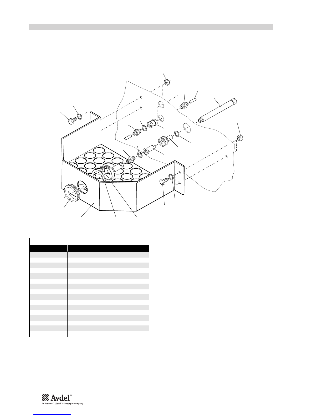
CABINET
The cabinet comprises an intensifier 3, a pilot valve 38, a pressure regulator and filtering unit 19 and an air pressure indicating
assembly 23 together with the air hoses internal to the cabinet.
Servicing is limited to removal/replacement of complete assemblies and the renewal of seals within the pilot valve.
To dismantle the cabinet it is necessary to extract the base plate 46 and the components installed on it. This is possible after
disconnecting all hoses and removing items restricting the withdrawal of the base plate.
INTENSIFIER
To remove the intensifier 3and oil reservoir, disconnect the oil hose using two spanners, (be prepared for oil spillage from hose/
intensifier), then remove the hoses (quick release connectors) connecting the intensifier to the pilot valve.
Using a spanner, remove the two nuts and associated washers securing the intensifier to the baseplate.
Lift intensifier clear of cabinet.
Replacement is in reverse order of removal.
14
* refers to items included in the Avdel service kit. For complete list see page 11.
■
■
■
■
■
■
■
■
■
■
■
■
■
■

PILOT VALVE
Servicing of the valve is limited to the removal/replacement of ‘O’ rings.
Remove screws 60 and remove pilot assembly .
Remove pilot valve 36 and discard ‘O’ rings 40, 47, 41 and 42.
Remove end cap screws 57 & 62 and remove end caps 58 & 61.
Withdraw pistons 54 & 49 and remove ‘O’ rings 44 & 46 from pistons.
Withdraw spool 52 from bore, taking care not to damage surface of spool and remove location washers 53 & 50, ‘O’ ring
45, spacers 51 and ‘O’ ring 43 from each end of valve body.
Remove the five interface ‘O’ rings.
Discard ALL ‘O’ rings removed.
Clean all parts with paraffin or white spirit (DO NOT USE SOLVENTS) and dry all parts.
Lightly smear bores of valve body 59, pilot valve body 55, both end caps 58 & 61 and all replacement ‘O’ rings with
“CENTOPLEX 2” grease.
Fit new seals 47, 41 and 42 to pilot valve piston 48 and insert into pilot valve body.
Fit new seals 40, 42 and 43 to pilot valve body, place top cap 56 in position and secure pilot valve assembly to the main valve
body 59 with screws 25. Ensure that the interface seal housing faces upward with the G1/4 at the bottom. Ensure orientation
of pilot valve 6is correct.
With main valve body 59 in the same position, fit green location washer 53 to the left hand side of the valve assembly.
Starting from the right hand side of the valve, assemble alternately the ‘O’ rings 45 and spacers 57 (6 ‘o’ rings and 5 spacers)
and finally complete the stack assembly with white location washer 1.
Lightly smear spool 52 with “CENTOPLEX 2” grease and slide spool through seal/spacer stack.
Fit seals 46 & 45 to respective pistons 54 & 49, fit seals 43 to ends of main valve body 59.
Insert pistons into end caps 58 & 61 and assemble end caps to valve, taking care to locate piston shafts into holes in the ends
of the spool 52.
Secure end cap assemblies to main valve body 59 with screws 57 & 62.
Fit interface ‘O’ ring into their housings in the main valve body.
If the pipe connection to the pilot assembly is damaged, replace the plastic collet 38 and lift out the ‘O’ ring from the cartridge
37. Fit new ‘O’ ring 39 and insert plastic collet 38 into the cartridge.
PRESSURE REGULATOR AND FILTERING ASSEMBLY
To remove the assembly from the cabinet, disconnect the two air hoses 47 & 42 at the regulator.
Remove the two screws, spacers, washers and nuts 19 securing the regulator to the cabinet.
Remove assembly from the cabinet.
Replacement is in reverse order of removal.
AIR PRESSURE INDICATOR ASSEMBLY
To remove the assembly 23, remove the air hose 42 from the rear of the gauge.
Remove the clamp from the rear of the gauge and withdraw gauge from front of the cabinet.
Replacement is in reverse order of removal.
15
* refers to items included in the Avdel service kit. For complete list see page 11.
■
■
■
■
■
■
■
■
■
■
■
■
■
■
■
■
■
■
■
■
■
■
■
■
■
■
■
I M P O R T A N T
Check the tool against daily and weekly servicing.
Priming is ALWAYS necessary after the tool has been dismantled and prior to operating.

16
32
31
28
23
23
27
26
26
33
30 29
24
23
25
123
6
7
13 15
14
9
10
12
36 34
35
39
40
38
37
11
8
16
18
19
20
21
22
5
17
4
41
42
43
42
GENERAL ASSEMBLY OF HANDLE TOOL 07265-03000
5M HOSE ASSEMBLY 07265-03000

17
ITEM PART Nº DESCRIPTION QTY SPARES ITEM PART Nº DESCRIPTION QTY SPARES
07265-03000 PARTS LIST
107265-03021 SUSPENSION RING 1-
207265-02011 WASHER 1 -
307265-02010 BLEED SCREW 1 -
407265-02003 WASHER 1 -
507265-02035 VACUUM SWITCH SCREW 1-
607265-03006 SEAL 1 -
707265-03018 SEAL 1 -
807265-02012 BUFFER 1 -
907265-02047 SCREW 2 -
10 07265-02046 PISTON STOP 1 -
11 07265-02009 'O' RING 2 -
12 07265-02007 'O' RING 2 -
13 07265-02008 STOP COVER 1 -
14 07265-02042 ADAPTOR 1 -
15 07265-02044 SCREW 3 -
16 07265-03002 PISTON 1 -
17 07265-02005 CIRCLIP 1 -
18 07265-02004 SEAL 1 -
19 07265-03001 HANDLE 1 -
20 07265-02031 WASHER 1 -
21 07265-02032 CONNECTOR 1 -
22 07265-03029 SLEEVE 1 -
23 07555-00502 'O' RING 3 -
24 07265-02016 SUCTION ADJUSTMENT SCREW 1-
25 07265-02037 VACUUM SWITCH 1-
26 07265-02020 'O' RING 2 -
27 07265-02019 RING 1 -
28 07555-09219 SPRING 1 -
29 07265-03024 'O' RING 1 1
30 07265-03022 LOCKNUT 1 -
31 07265-03023 TRIGGER 1 -
32 07265-02017 SCRAPER RING 1 -
33 07265-03015 END PLUG 1 -
34 07265-03800 STEM CATCHER UNIT 1-
35 07640-00241 INNER BODY 1 -
36 07265-02013 SCREW 2 -
37 07640-00239 OUTER BODY 1 -
38 07340-00335 END CAP 1 -
39 07265-02054 SILENCER 1 -
40 07265-03051 END COVER 1 -
ITEM PART Nº DESCRIPTION QTY SPARES ITEM PART Nº DESCRIPTION QTY SPARES
5M HOSE ASSEMBLY 07265-03500
41 07265-02061 OIL HOSE 1 -
42 07265-02021 AIR HOSE 2 -
43 07265-02066 PROTECTIVE SLEEVE 1-

H
B
E
L
H
K
D
C
H
E
3
27
40
49 35
41
20
36
51
14
14
12
20
14
21
43
42
4
5
6
24
22
15
14
13 1
28
14
52
14
37
19
17 18
17
16
12
14
19
48
44
45
47
46
26
23
25
3
8
39
50
2
9
2
12
N
30
31
34
32
33
N
C
N
KD
B
N
B
L
N
9
10
87
11
18
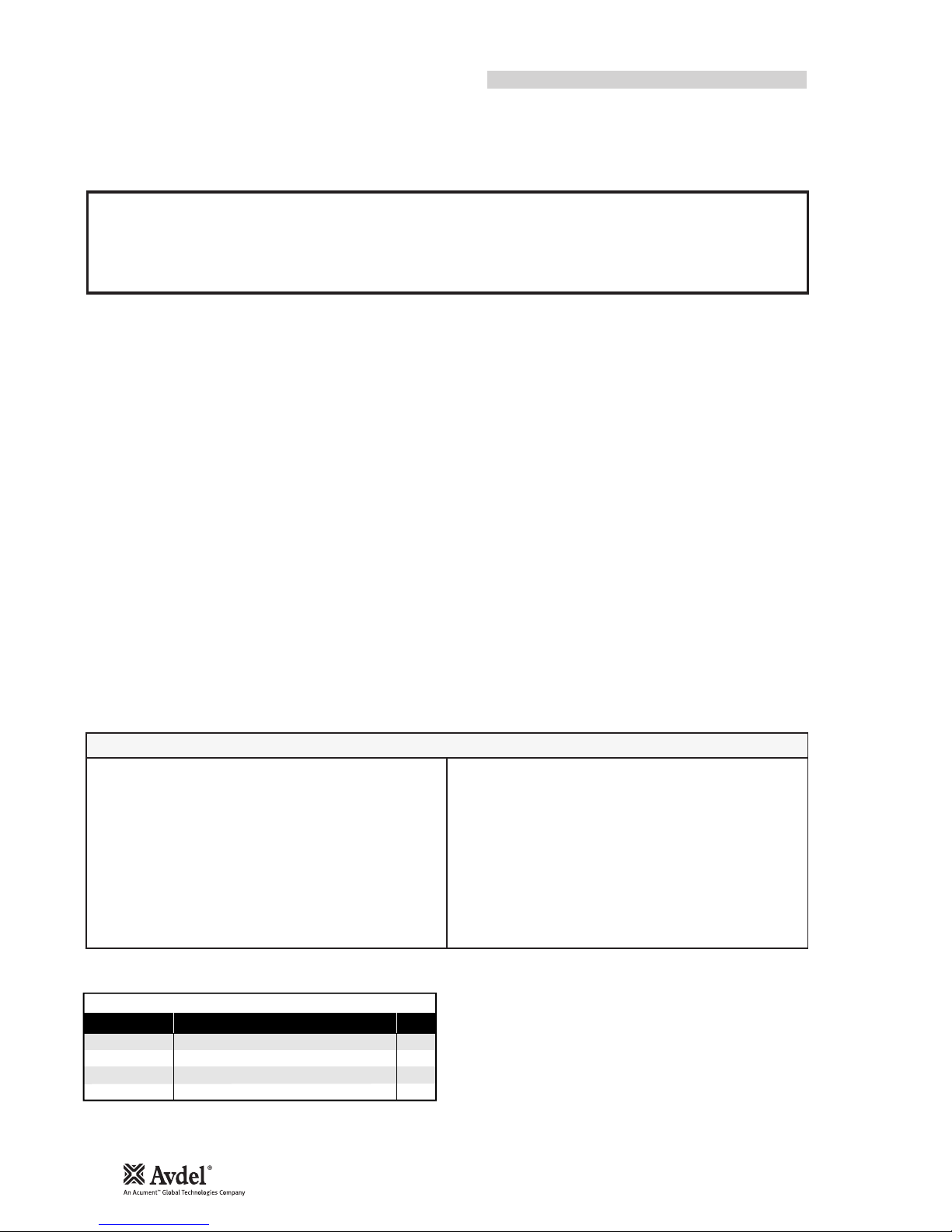
GENERAL ASSEMBLY OF CABINET 07265-03200
Other manuals for 7265
1
Table of contents
Other Avdel Power Tools manuals

Avdel
Avdel Genesis G2LB User manual

Avdel
Avdel Genesis 4 User manual

Avdel
Avdel 0749 MkII type User manual

Avdel
Avdel 0753 MkII User manual

Avdel
Avdel 07572 User manual

Avdel
Avdel 7385 User manual

Avdel
Avdel 74100 User manual

Avdel
Avdel 74200 User manual

Avdel
Avdel Genesis G3 HD User manual

Avdel
Avdel 753 MkII User manual

Avdel
Avdel Genesis G3 User manual

Avdel
Avdel 74405 User manual

Avdel
Avdel Genesis G4 HD Heavy Duty User manual

Avdel
Avdel Genesis G1 User manual

Avdel
Avdel 74110 User manual

Avdel
Avdel T40 User manual

Avdel
Avdel Genesis nG2s User manual

Avdel
Avdel 71234 User manual

Avdel
Avdel 74401 User manual

Avdel
Avdel G3LB Tool User manual


