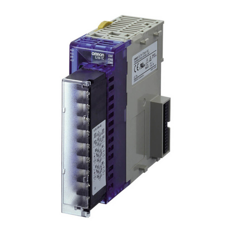
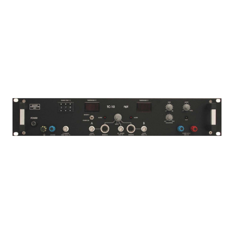
Thermon TC 816 User manual

Thermon Europe B.V. Tel.: +31 (0)15 36 15 370
Boezemweg 25 Fax: +31 (0)15 36 15 379
2641 KG Pijnacker
The Netherlands
AF TC4/5 firmware: AZ848/849 rev.2.00
TCD 01 firmware: AZ871 rev.2.43 / AZ884 rev.2.50
Operation Manual 200508 E TC 816
TC 816
Operation Manual
TCD 01
Tracing Control Display
TCD 01
Tracing Control Display

TC 816 Operation Manual
THERMON…The Heat Tracing Specialists®
Page 2 of 42 Operation Manual 0503 E TC 816
Table of contents
1INTRODUCTION....................................................................................................................................................4
1.1 POSSIBLE CONTROL CONCEPTS ..........................................................................................................................4
1.1.1 Process Temperature Maintenance or Proportional Ambient Control.........................................................4
1.1.2 Frost Protection with Staged Start-Up .........................................................................................................4
1.1.3 Heat Tracing Cable Temperature Limiter ....................................................................................................4
2THE TC 816 FOR PROCESS TEMPERATURE MAINTENANCE..................................................................5
2.1 SLOT 1: FOR AF TPA THERMON POWER SUPPLY MODULE AC...........................................................................5
2.2 SLOT 2: FOR AF TC4 OR AF TC5 TRACING CENTRAL PROCESSING MODULE.....................................................5
2.3 SLOT 3: FOR AF TIT TRACING INPUT MODULE FOR TEMPERATURE ...................................................................6
2.4 SLOT 4: FOR AF TIT TRACING INPUT MODULE FOR TEMPERATURE OR ZD TB1 BLIND PLATE...........................6
2.5 SLOT 5: FOR AF TOE TRACING OUTPUT MODULE FOR ELECTRONIC RELAYS OR AF TOM TRACING OUTPUT
MODULE FOR MECHANICAL CONTACTORS .......................................................................................................................6
2.5.1 AF TOE Tracing Output module for Electronic relays.................................................................................6
2.5.2 AF TOM Tracing Output module for Mechanical contactors.......................................................................6
2.6 SLOT 6: FOR AF TIC TRACING INPUT MODULE FOR LOAD CURRENT OR ZD TB1 BLIND PLATE .........................6
3THE TCD 01 TRACING CONTROL DISPLAY .................................................................................................7
3.1 DESCRIPTION OF THE TCD 01 ............................................................................................................................8
3.2 START-UP OF THE TCD 01..................................................................................................................................9
3.3 CONFIGURATION OF THE TCD 01 IN GENERAL SETTINGS (SETUP) MENU ......................................................10
3.3.1 Number of First Circuit...............................................................................................................................11
3.3.2 Password.....................................................................................................................................................11
3.3.3 Language (1=D, 2=E, 3=F, 4=NL)............................................................................................................11
3.3.4 Selftest Cycle Time......................................................................................................................................11
3.3.5 Baudrate......................................................................................................................................................11
3.4 PASSWORD INPUT.............................................................................................................................................12
3.5 DATA COMMUNICATION BUS SEARCH .............................................................................................................13
3.6 HEAT TRACING CIRCUIT DISPLAY....................................................................................................................15
3.6.1 Heat Tracing Circuit Numbers and TC 816 Zone Numbers .......................................................................16
3.6.2 Controller and Zone Assignment
[C01Z01]
........................................................................................17
3.6.3 Column:
MEASURED
..............................................................................................................................17
3.6.4 Column:
SETPOINT
..............................................................................................................................17
3.6.5 Column:
ALARM
.......................................................................................................................................18
3.7 ACKNOWLEDGE CONTROLLER AND CURRENT ALARMS ...................................................................................20
3.8 ACKNOWLEDGE HEAT TRACING CABLE TEMPERATURE LIMITER TRIPS...........................................................21
3.9 CHANGING SET POINTS ....................................................................................................................................23
3.10 CHANGING PARAMETER VALUES .....................................................................................................................24
4PARAMETERS......................................................................................................................................................26
4.1 ALTERING PARAMETERS ..................................................................................................................................26
4.2 ZONE PARAMETERS TO BE CONFIGURED THROUGH TCD 01 TRACING CONTROL DISPLAY ................................26
4.2.1 Parameter P01:
LO-ALARM
...................................................................................................................26
4.2.2 Parameter P02:
HI-ALARM
...................................................................................................................27
4.2.3 Parameter P03:
DEV-ALARM
................................................................................................................27
4.2.4 Parameter P04:
AL DELAY
...................................................................................................................28
4.2.5 Parameter P05:
DIGI IN
.....................................................................................................................29
4.2.6 Parameter P06:
OP MODE
.....................................................................................................................30
4.2.7 Parameter P07:
MAN OUTP
...................................................................................................................31
4.2.8 Parameter P08:
MAX OUTP
...................................................................................................................32
4.2.9 Parameter P09:
AV OUTP
.....................................................................................................................32
4.2.10 Parameter P10:
OFFSET
....................................................................................................................32
4.2.11 Parameter P11:
COIL FACT
...........................................................................................................33

TC 816 Operation Manual
THERMON…The Heat Tracing Specialists®
Operation Manual 0503 E TC 816 Page 3 of 42
4.2.12 Parameter P12:
ON DELAY
..............................................................................................................33
4.2.13 Parameter P13: Spare............................................................................................................................34
4.2.14 Parameter P14: Spare............................................................................................................................34
4.2.15 Parameter P15: Spare............................................................................................................................34
4.3 ZONE PARAMETERS CONFIGURED BY HEAT TRACING SUPPLIER........................................................................35
4.3.1 Parameter P16:
LIM ADDR
...................................................................................................................35
4.3.2 Parameter P17:
LIM ZONE
...................................................................................................................35
4.3.3 Parameter P18:
CTR MODE
...................................................................................................................36
4.3.4 Parameter P19:
P HEAT
........................................................................................................................37
4.3.5 Parameter P20:
I HEAT
........................................................................................................................37
4.3.6 Parameter P21:
D HEAT
........................................................................................................................38
4.3.7 Parameter P22:
APC MIN T
................................................................................................................38
4.3.8 Parameter P23: Spare ................................................................................................................................38
4.3.9 Parameter P24:
HYSTER
........................................................................................................................39
4.3.10 Parameter P25:
CYCL TIME
...........................................................................................................39
4.3.11 Parameter P26:
SENSOR #
..............................................................................................................40
4.3.12 Parameter P27:
OUTP #
....................................................................................................................41
4.3.13 Parameter P28:
MS MODE
.................................................................................................................42
4.3.14 Parameter P29: Spare............................................................................................................................42

TC 816 Operation Manual
THERMON…The Heat Tracing Specialists®
Page 4 of 42 Operation Manual 0503 E TC 816
1Introduction
The Thermon TC 816 is a multi circuit temperature controller concept developed for Electrical Heat Tracing
control. This concept allows total electrical heat tracing control configured to the needs of the customer.
The TC 816 hardware is based on electronic modules. With this approach the TC 816 can be set up for a
huge variety of control tasks required for all electric heat tracing concepts Thermon has to offer.
The TC 816 facilitates one or two data communication busses through which it can either be connected to the
Thermon TCD 01 tracing control display, a remote computer running a control and monitoring program
and/or a DCS system.
Up to 30 TC 816 temperature controllers can be interconnected through the data communication bus(ses) to
their host(s). Each communication bus has one host, being either the TCD 01 tracing control display, the
computer running the control and monitoring software and/or a DCS system.
1.1 Possible Control Concepts
The controller can be configured per controller and with process temperature maintenance per heat tracing
circuit for different control concepts. However all controller regardless of how they are configured can com-
municate on one data communication bus.
This operation Manual addresses exclusively the Process Temperature Maintenance concept of the TC 816 in
conjunction with the TCD 01 tracing control display.
1.1.1 Process Temperature Maintenance or Proportional Ambient Control
•Proportional Integral Differential process temperature maintenance
•ON/OFF process temperature maintenance with configurable hysteresis in °C or °F
•Dummy Pipe or Dead Leg sensing process temperature maintenance
•Multiple Sensor MODE featuring minimum, average or maximum temperature control offering redundant
sensors in the event of a broken RTD or connection to the RTD
•Ambient Proportional Control (also suitable for frost protection)
1.1.2 Frost Protection with Staged Start-Up
•Ambient ON/OFF control with staged start up
1.1.3 Heat Tracing Cable Temperature Limiter
This control concept is required for electrical heat tracing systems in hazardous area (potentially explosive
atmospheres) which do not comply with the rated T-class.
The heating cables sheath temperature is sensed, when the sheath temperature exceeds the controller’s tem-
perature set point the controller switches the heat tracing off and generates a high temperature alarm. The
heat tracing can only be switched back on manually if the high temperature condition has recovered.

TC 816 Operation Manual
THERMON…The Heat Tracing Specialists®
Operation Manual 0503 E TC 816 Page 5 of 42
2The TC 816 for Process Temperature Maintenance
The enclosure of the TC 816 is constructed to be mounted on the back plane of a panel. The enclosure facili-
tates 6 slots for electronic modules, each having its particular task.
Below the slots and the possible modules are described from the most right position to the left:
2.1 Slot 1: For AF TPA Thermon Power supply module AC
The AF TPA module is a multi voltage switching power supply suitable for voltages between 85 and 265 Vac
50/60 Hz.
This module also facilitates voltage free alarm contacts for:
•HI-Alarm: - high temperature
- high current (only if AF TIC module is applied in slot 6)
- open or short circuited RTD sensor
•LO-Alarm: - low temperature
- low current (only if AF TIC module is applied in slot 6)
•DEV-Alarm:- too much deviation from temperature set point
- too much deviation from load current set point (only if AF TIC module is applied in slot 6)
•System-Al.: Hardware controlled self check
2.2 Slot 2: For AF TC4 or AF TC5 Tracing Central processing module
The AF TC4 or AF TC5 can be inserted into slot 2 as central processing module. The central processing mod-
ule is the intelligence of the TC 816. It allows the controller independent operation. This means, that the TC
816 can operate even if the communication bus is disconnected.
The non volatile memory of the AF TC4 and AF TC5 modules enables fast and safe start-up and recovery after
eventual power failures. The last set parameter values are still stored in the memory.
The AF TC4 central processing module facilitates a 24 Vdc digital input and 2 separate RS 485 communication
busses (utilising galvanic separation).
The AF TC5 central processing module facilitates a 24 Vdc digital input, a RS 485 communication bus and
independent standard Profibus connection (both interfaces utilising galvanic separation).

TC 816 Operation Manual
THERMON…The Heat Tracing Specialists®
Page 6 of 42 Operation Manual 0503 E TC 816
2.3 Slot 3: For AF TIT Tracing Input module for Temperature
The AF TIT is an 8 circuit, 4 wire, RTD PT 100 temperature input module. By bridging the compensation ter-
minals this module is also suitable foe 3 wire and 2 wire RTD PT 100 sensors.
2.4 Slot 4: For AF TIT Tracing Input module for Temperature or ZD TB1 blind
plate
Whether slot 4 is equipped with an AF TIT module or with a ZD TB1 blind plate determines whether the TC
816 is set up for 16 or 8 heat tracing circuits.
2.5 Slot 5: For AF TOE Tracing Output module for Electronic relays or AF TOM
Tracing Output module for Mechanical contactors
2.5.1 AF TOE Tracing Output module for Electronic relays
The AF TOE utilises 2 terminals for external 24 Vdc power supply in order to provide enough capacity to drive
up to 16 solid state relays or small 24Vdc driven mechanical contactors.
In general this module is applied if PID process temperature maintenance control (also for dummy pipe or
dead leg sensing) or ambient proportional control is required. Solid state relays are the best solutions for
those control concepts because they do not wear out considering the amount of switch actions they have to
fulfil.
The advantage is, that off the shelf Solid State relays can be connected to the TC 816 so switching capacity of
a TC 816 system is only limited by the panel construction parameters like feeding power, cooling capacity in
the panel.
Additional this module offers the unique possibility of digital inputs (24Vdc) enabling to:
•monitor status of 16 individual MCB/RCD units through the MDB/RCD’s auxiliary contact(s)
•monitor for instance signals from DCS or switches in order to set Parameter P06 OP MODE to “dis-
able Zone operation” (see chapter 4.2.6). This can for used to for instance for maintenance purposes.
Only the AF TOE module offers this feature.
2.5.2 AF TOM Tracing Output module for Mechanical contactors
The AF TOM utilises 16 voltage free contactors capable of driving up to 250 Vac mechanical contactor coils.
2.6 Slot 6: For AF TIC Tracing Input module for load Current or ZD TB1 blind
plate
Whether slot 6 is equipped with an AF TIC module or with a ZD TB1 blind plate determines whether the TC
816 is set up for current load monitoring or not.
The AF TIC tracing Input module for load current facilitates 16 current transformer inputs. To those inputs the
AT T4I DIN rail mounted 4 circuit current transformer module has to be connected. One AT T4I module facili-
tates current monitoring for 4 circuits. In order to fully equip the AF TIC 4 AT T4I modules are needed, this
provides current monitoring for 16 circuits.
In addition the AF TIC utilizes a voltage compensation input. To this input either a fixed resistor (default factory
delivery) or AT TU1 DIN rail mounted voltage compensation module can be connected. This option enables
automatic current set point shifting to avoid current deviation alarms in case of supply voltage variations,
which can be common in industrial environment. This option should only be applied with constant watt heat
tracing cables.

TC 816 Operation Manual
THERMON…The Heat Tracing Specialists®
Operation Manual 0503 E TC 816 Page 7 of 42
3The TCD 01 Tracing Control Display
The TCD 01 tracing control display allows the operator to have full control over the heat tracing circuits which
are controlled by the connected TC 816 temperature controllers.
The TCD 01 is the host on the RS 485 data communication bus. It searches on the communication bus for TC
816 heat tracing temperature controllers which need to have their own unique communication address (to be
set by DIP switches on the AF TC4 tracing central processing module).
The TCD 01 tracing control display shall be powered by an external 24 Vdc power supply. That supply can be
the same providing the 24 Vdc power to drive the solid state relays or mechanical contactors in the panel.
Two versions of the TCD 01 are available.
•A TCD 01 for single phase current display per tracing circuit (firmware AZ 871)
•A TCD 01 for three phase current display per tracing circuit (firmware AZ 884)

TC 816 Operation Manual
THERMON…The Heat Tracing Specialists®
Page 8 of 42 Operation Manual 0503 E TC 816
3.1 Description of the TCD 01
TCD 01
Tracing Control Display
Figure 4.1 TCD 01 Tracing Control Display
Description of buttons and indication lights:
, Down Button:
Allows you to scroll down particular set points, parameter numbers etc. as shown in the display above the
applicable down button.
Pressing this button for a short time decreases by single steps, holding it will accelerate the scroll.
, Up Button:
Allows you to scroll up particular set points, parameter numbers etc. as shown in the display above the appli-
cable down button.
Pressing this button for a short time decreases by single steps, holding it will accelerate the scroll.
, Enter Button:
Is generally used to enter or save settings. However, sometimes can have a different function as shown in the
display above this particular button.
, Acknowledge Button:
Is generally used to acknowledge alarms. After acknowledging alarms of one heat tracing circuit the TCD 01
tracing control display will automatically show the next circuit with alarm conditions to be acknowledged.
, Tracing Alarm Light:
Illuminates when an un-acknowledged Alarm condition is detected in a controller connected to the data
communication bus. The TCD 01 tracing control display will automatically show the circuit with alarm condi-
tions to be acknowledged.
, TCD 01 System Alarm Light:
Illuminates when the hardware controlled self check detects a program stop in the TCD 01 tracing control
display

TC 816 Operation Manual
THERMON…The Heat Tracing Specialists®
Operation Manual 0503 E TC 816 Page 9 of 42
3.2 Start-up of the TCD 01
After:
•having setup the hardware wiring of the RS 485 data communication bus
•setting the communication address of the connected TC 816 controllers
•and applying the 24 Vdc power supply
The TCD 01 tracing control display illuminates yellow and looks as below:
Figure 4.2 TCD 01 Tracing Control Display: Start-Up (Version and date might differ from illustra-
tion)

TC 816 Operation Manual
THERMON…The Heat Tracing Specialists®
Page 10 of 42 Operation Manual 0503 E TC 816
3.3 Configuration of the TCD 01 in General Settings (SETUP) Menu
By pressing the and buttons below SETUP simultaneously you can enter the General Settings
menu.
At any time in any display the General Settings Menu can be entered by pressing the same buttons simulta-
neously.
The General Settings menu can be left without saving changes by pressing the and buttons below
EXIT simultaneously. If you want to save changes and leave this menu press the button below SAVE
or press the button. Pressing the button will additionally cause a restart of the TCD 01 and rescan of
the communication bus.
Figure 4.3 TCD 01 Tracing Control Display: General Settings Menu
By pressing the or buttons below SELECTION you can select the appropriate parameter to be
changed.
By pressing the or buttons below SETPOINT you can change the values of the parameters.

TC 816 Operation Manual
THERMON…The Heat Tracing Specialists®
Operation Manual 0503 E TC 816 Page 11 of 42
Figure 4.3 TCD 01 Tracing Control Display: General Settings Menu
In the General Setting Menu following parameters can be set:
3.3.1 Number of First Circuit
This number determines the first visual circuit number to be shown in the display. This feature is very handy
in case multiple heat tracing control panels are required in one plant. It enables unique heat tracing circuit
numbers throughout the plant.
3.3.2 Password
Here a security password, a 3 digit number can be set for parameter and General Settings Menu protection.
For changing temperature or load current set point no password is needed. Do never forget the password
number. Note it down where only authorised personnel can find it.
000: means no password protection of parameters
NOTE: The password must always be set in case a TC 816 configured as Heat Tracing Cable Temperature
Limiter is connected to the TCD 01. It ensures that all trips of that safety device can only be acknowl-
edged through a password, as required for temperature protection devices in hazardous areas
(potentially explosive atmospheres)
3.3.3 Language (1=D, 2=E, 3=F, 4=NL)
With this parameter the TCD 01 text language can be changed between German (D for “Deutsch”) and Eng-
lish.
001: Deutsch (German)
002: English, Default
003: Francaise (French)
004: NederLands (Dutch)
3.3.4 Selftest Cycle Time
This parameter determines the period in hours after which the TCD 01 prompts the connected TC 816 con-
trollers to check the alarm status again.
3.3.5 Baudrate
With this parameter, the Baud rate can be selected. The options are 9.600 Baud and 19.200 Baud. The
19200 Baud must be used when using eg MODbus communication

TC 816 Operation Manual
THERMON…The Heat Tracing Specialists®
Page 12 of 42 Operation Manual 0503 E TC 816
Password Input
When in the General Settings Menu a password is set to other than 000 (see chapter 3.3.2), the following
display will prompt you to enter the password whenever you try to change a set point. The password has not
to be re entered as long as the two brackets are shown around a set point in the display or you are still in a
parameter menu (see chapter 3.7 and 3.10).
TCD 01
Tracing Control Display
Figure 4.4 TCD 01 Tracing Control Display: Password Input
You can change the value of the password field by pressing the or buttons below PASSWORD to
the password which was set in the General Settings Menu.
The password value is entered with the ENTER button . If the password is correct the TCD 01 continues
to the desired Parameter display or to the General Settings Menu.

TC 816 Operation Manual
THERMON…The Heat Tracing Specialists®
Operation Manual 0503 E TC 816 Page 13 of 42
3.5 Data Communication Bus Search
After the Start-Up screen is left automatically or the General Settings Menu has been left by pushing the ac-
knowledge button, the TCD 01 starts searching the RS 485 communication bus for connected TC 816 heat
tracing temperature controllers.
TCD 01
Tracing Control Display
Figure 4.5 TCD 01 Tracing Control Display: Data Communication Bus Search
As shown in figure 4.5 a RS 485 data communication bus with up to 30 controllers can be hosted by the TCD
01. Therefore up to 480 (16 x 30) heat tracing circuits can be connected to one TCD 01 tracing control dis-
play.
Every controller is listed by its set communication address. When a controller is detected it is automatically
checked for what kind of control concept the controller is configured and for how many circuits.
The display shows next to the 30 possible communication addresses:
•?: No controller assigned
•CONT: Controller configured for Process Temperature Maintenance or Proportional Ambient Control
(see chapter 1.1.1)
•FPSS: Controller configured for Frost Protection with Staged Start-Up (see chapter 1.1.2)
•LIM: Controller configured for Heat Tracing Cable Temperature Limiter (see chapter 1.1.3)

TC 816 Operation Manual
THERMON…The Heat Tracing Specialists®
Page 14 of 42 Operation Manual 0503 E TC 816
After the data communication bus search is completed choices are offered to the user how to deal with the
result of the bus search, see figure 4.6.
TCD 01
Tracing Control Display
Figure 4.6 TCD 01 Tracing Control Display: Bus Configuration
•RESCAN: In case not all expected controllers are show the missing controller can be
(re)connected to the bus system or faulty communication address settings corrected
and the bus can be re-scanned. Press the or buttons below RESCAN.
•CONFIRM: Accept/confirm the bus configuration by pressing the or buttons below
CONFIRM.
•SKIP: In the event a controller is disconnected from the bus system, but the circuit
numbers in the TCD 01 Tracing Control Display have to remain as before the
controller was disconnected press the or buttons below SKIP to ignore the
displayed result of the bus scan and operate the TCD 01 with the original circuit
numbers.
After choosing CONFIRM or SKIP the TCD 01 automatically switches to heat tracing circuit display.

TC 816 Operation Manual
THERMON…The Heat Tracing Specialists®
Operation Manual 0503 E TC 816 Page 15 of 42
3.6 Heat Tracing Circuit Display
After the Data Communication Bus Search has been completed the TCD 01 tracing control display shows the
following.
Two versions of the TCD 01 are available.
•A TCD 01 for single phase current display per tracing circuit, with firmware AZ 871, see figure 4.7
•A TCD 01 for three phase current display per tracing circuit, with firmware AZ 884, see figure 4.8
TCD 01
Tracing Control Display
Figure 4.7 TCD 01 Tracing Control Display: Heat Tracing Circuit Display for single phase cur-
rent display
TCD 01
Tracing Control Display
Figure 4.8 TCD 01 Tracing Control Display: Heat Tracing Circuit Display for three phase current
display
By pressing the or buttons below CIRCUIT you can scroll through the heat tracing circuits.

TC 816 Operation Manual
THERMON…The Heat Tracing Specialists®
Page 16 of 42 Operation Manual 0503 E TC 816
Description:
3.6.1 Heat Tracing Circuit Numbers and TC 816 Zone Numbers
In order to properly configure the TC 816 it is very important to know the difference between heat tracing
circuit numbers and TC 816 Zone numbers. In this manual referred to as circuit numbers and zone numbers.
Zone Numbers:
Each TC 816 could count up to 32 analogue inputs depending on its configuration. Each analogue input is
called a Zone. With the TC 816 there is a clear distinction between temperature input Zones and current input
zones. The type of Zone can easily be recognised by their number:
•Zone 1 through 16: Temperature input Zones (2 x AF TIT, each 8 Zones)
•Zone 17 through 32: Load current input Zones (1 x AF TIC, 16 Zones)
For each particular Zone, 29 so called Zone parameters can be set.
Circuit Numbers:
Multiple Zone numbers of particular TC 816 controllers can be assigned to one Heat Tracing Circuit Number.
For instance, the in Figure 4.6 displayed Circuit 001 could include analogue inputs (Zones) for:
•A pipe temperature control (CONTROLLER-line), using:
Zone 1 of TC 816 controller with communication address 1.
•A temperature sensor for heat tracing cable temperature limitation (LIMITER-line), using:
Zone 1 of TC 816 controller (configured for Heat Tracing Cable Temperature Limiter concept) with
communication address 2.
•A load current input for heat tracing circuit load current monitoring (CURRENT-line) , using:
Zone 17 of TC 816 controller with communication address 1.
The TC 816 automatically assigns Zone 17 to Zone 1 of the same controller if at start-up an AF TIC Tracing
Input module for load Current is detected.

TC 816 Operation Manual
THERMON…The Heat Tracing Specialists®
Operation Manual 0503 E TC 816 Page 17 of 42
3.6.2 Controller and Zone Assignment [C01Z01]
The indication [C01Z01] behind the circuit number in the top line of the display is:
•C01: the assigned TC 816 communication address
•Z01: the assigned controller Zone number of the applicable TC 816 controller. With CURRENT
values and LIMITER values some analogue inputs are linked together as one circuit,
only the CONTROLLER Zone number is mentioned.
This indication gives a clear reference for the operator in case of alarm which controller and panel to check
out.
3.6.3 Column: MEASURED
This column shows:
•In the CONTROLLER-line: Measured pipe temperature
- Applicable for controller-Zones 1 through 16
- Units:
°C or °F (depending on DIP-switch setting for temperature units)
•In the LIMITER-line: Measured heat tracing cable temperature
- Only applicable if a limiter-Zone (from a separate TC 816
controller) is assigned to this particular heat tracing circuit, by
parameters P16 and P17 of the controller Zone.
- Units:
°C or °F (depending on DIP-switch setting for temperature units)
•In the CURRENT-line(s): Measured load current(s)
- Only applicable if AF TIC Tracing Input module for load Current is
installed, controller-Zone 17 through 32
- Unit: A
3.6.4 Column: SETPOINT
This column shows:
•In the CONTROLLER-line: Set point for pipe temperature
- Applicable for controller-Zones 1 through 16
- Units:
°C or °F (depending on DIP-switch setting for temperature units)
•In the LIMITER-line: Set point for maximum heat tracing cable sheath temperature
- Only applicable if a limiter-Zone (from a separate TC 816
controller) is assigned to this particular heat tracing circuit, by
parameters P16 and P17 of the controller Zone.
- Units:
°C or °F (depending on DIP-switch setting for temperature units)
•In the CURRENT-line(s): Set point for load current
- This set point is for load current DEV-ALARM (deviation alarm)
reference only, the TCD 01 heat tracing temperature
controller does not control the load current, it does monitor it.
- Only applicable if AF TIC Tracing Input module for load Current is
installed, controller-Zone 17 through 32
- Unit: A

TC 816 Operation Manual
THERMON…The Heat Tracing Specialists®
Page 18 of 42 Operation Manual 0503 E TC 816
3.6.5 Column: ALARM
This column shows:
•In the CONTROLLER- line (controller-Zones 1 through 16):
-OK.-: No alarm condition
-L-: Low temperature alarm condition
Measured temperature dropped below the LO-ALARM set point (parameter P01)
-H-: High temperature alarm condition
Measured temperature exceeded the HI-ALARM set point (parameter P02)
-DEV-: DEViation temperature alarm condition
Trips in case of:
- Measured temperature dropped below the value:
controller temperature set point - DEV-ALARM set point (parameter P03)
-Measuredtemperature exceeded the value:
controller temperature set point + DEV-ALARM set point (parameter P03)
-I-: Load current alarm condition
Trips in case of:
- The MCB/RCD AL auxiliary contacts are wired to the digital inputs of the AF TOE
Tracing Output module for Electronic relays and parameter P05 enables MCB/RCD
monitoring.
- The AF TIC Tracing Input module for load Current is installed and a alarm condition
inthe
CURRENT-line of the TCD 01 display occurs.
-E-: Sensor alarm condition
Trips in case of:
- Short circuited RTD input on AF TIT Tracing Input module for Temperature
- Open RTD input on AF TIT Tracing Input module for Temperature
-com-: Communication alarm condition
The TCD 01 tracing control display can not access the measure controller
value or set point through the RS 485 data communication bus.
-OFF-: Alarm condition monitoring disabled
This situation occurs if the heat tracing circuit is set to manual or OFF
(parameter P06)
•In the LIMITER-line (limiter-Zones 1 through 16):
-OK.-: No alarm condition
-H-: High temperature alarm condition
Measured temperature exceeded the limiter set point
-com-: Communication alarm condition
The TCD 01 tracing control display can not access the measure controller
value or set point through the RS 485 data communication bus.
-OFF-: Alarm condition monitoring disabled
This situation occurs if the heat tracing circuit is set to manual or OFF
(parameter P06)

TC 816 Operation Manual
THERMON…The Heat Tracing Specialists®
Operation Manual 0503 E TC 816 Page 19 of 42
•In the CURRENT-line (controller-Zones 17 through 32):
-OK.-: No alarm condition
-L-: Low current alarm condition
Measured current dropped below the LO-ALARM set point (parameter P01)
-H-: High current alarm condition
Measured current exceeded the HI-ALARM set point (parameter P02)
-DEV-: DEViation current alarm condition
Trips in case of:
- Measured current dropped below the value:
controller current set point - DEV-ALARM set point (parameter P03)
- Measured current exceeded the value:
controller current set point + DEV-ALARM set point (parameter P03)
-com-: Communication alarm condition
The TCD 01 tracing control display can not access the measure controller
value or set point through the RS 485 data communication bus.
-OFF-: Alarm condition monitoring disabled
This situation occurs if the heat tracing circuit is set to manual or OFF
(parameter P06)

TC 816 Operation Manual
THERMON…The Heat Tracing Specialists®
Page 20 of 42 Operation Manual 0503 E TC 816
3.7 Acknowledge Controller and Current Alarms
In case an alarm occurs, the TCD 01 Tracing Control Display will automatically show the heat tracing circuit
where the latest alarm occurred. In the CONTROLLER- or CURRENT- lines the applicable alarm code
is displayed and an message appears in the top right corner PRESS (Q) TO ACK.
•TCD 01 for single phase current display per tracing circuit, with firmware AZ 871, will in addition give a
beep as audible alarm.
•TCD 01 for three phase current display per tracing circuit, with firmware AZ 884, will not sound an audi-
ble alarm.
Also the applicable hardware alarm contacts of the AF TPA Thermon Power supply module AC trip (see TC
816 Hardware Configuration Guide).
TCD 01
Tracing Control Display
Figure 4.9 TCD 01 Tracing Control Display: Heat Tracing Circuit Display with low temperature
alarm trip, as example
Acknowledge the alarm as follows:
1. Press the button.
2. The TCD 01 will display either:
a. Remain in the same circuit showing --ACKNOWLEDGED-- in the top right corner of
the display, see figure below.
or
b. Jump to another circuit which is an un-acknowledged alarm status.
TCD 01
Tracing Control Display
Figure 4.10 TCD 01 Tracing Control Display: Heat Tracing Circuit Display with low temperature
alarm trip, as example
Table of contents
