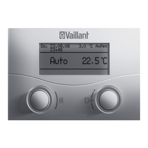
Vaillant VRC 400 Operating and Specification sheet

For the owner and the heating engineer
Operating and Installation Manual
VRC 400
Programmable weather compensator with separat HW time control
GB

2
Contents
Operating manual and installation manual for VRC 400 weather compensator
Contents
Notes on the documentation . . . . . 4
Symbols used........................................... 4
Storage of the documents.................... 4
Safety . . . . . . . . . . . . . . . . . . . . . . . . 5
Operating manual. . . . . . . . . . . . . . . 6
1 Control overview. . . . . . . . . . . . 6
2 Display overview. . . . . . . . . . . . 7
3 Description of the control . . . . 8
4 Operation. . . . . . . . . . . . . . . . . . 9
4.1 Setting the operating modes ...... 9
4.2 Setting the current day and
time ................................................... 12
4.3 Setting timer programmes .......... 13
4.4 Setting the room temperature ... 16
4.5 Setting the hot water
temperature .................................... 19
4.6 Activating special functions........ 20
4.7 Info level........................................... 22
5 Vaillant warranty . . . . . . . . . . . 23
6 Recycling and disposal. . . . . . . 24

3Operating manual and installation manual for VRC 400 weather compensator
Contents
Installation manual . . . . . . . . . . . . . 25
7 Information on installation
and operation . . . . . . . . . . . . . . 25
7.1 CE label............................................. 25
7.2 Intended use.................................... 25
8 Safety instructions and
regulations . . . . . . . . . . . . . . . . 26
8.1 Safety instructions ........................ 27
8.2 Regulations...................................... 27
9 Installation . . . . . . . . . . . . . . . . 28
9.1 Control installation ........................ 28
9.2 Wall mounting................................. 28
9.3 Installing the VRC 693 outdoor
sensor ............................................... 30
10 Electrical installation. . . . . . . . 33
10.1 Connecting the weather
compensator ................................... 34
10.2 Connecting the outside sensor... 34
11 Start-up. . . . . . . . . . . . . . . . . . . 35
11.1 Installer level................................... 36
11.2 Service/diagnostic level................ 40
11.3 Handing over to the owner.......... 42
12 Technical data. . . . . . . . . . . . . . 43
13 Vaillant customer service . . . . 43

4Operating manual and installation manual for VRC 400 weather compensator
Notes on the documentation
The following information is intended to
help you throughout the entire docu-
mentation. Further documents apply in
combination with this installation and
operation manual.
We accept no liability for any damage
caused by failure to observe these
instructions.
Symbols used
Please observe the safety instructions in
this manual for the installation of the
control.
Danger
Immediate risk of serious injury
or death
• Symbol for a necessary task
Storage of the documents
Please pass on this operating and installa-
tion manual to the owner of the system
so that he can keep it available whenev-
er it is required.

5Operating manual and installation manual for VRC 400 weather compensator
Safety
Safety
The weather compensator must be
installed by a qualified engineer, who is
responsible for adhering to the existing
standards and regulations.
We accept no liability for any damage
caused by failure to observe these
instructions.

6Operating Manual for VRC 400 weather compensator
1 Control overview
Operating manual
1 Control overview
1
2
Fig. 1.1 Control overview
Key
1 Display
2 Dial (turn and click)
I Info button
F Special functions button
P Programming button/installer level

7Operating Manual for VRC 400 weather compensator
Display overview 2
2 Display overview
9
1
10
2
3
11
12
4
7
8
6
5
Fig. 2.1 Overview of display
Key
1 Installer level and
service/diagnosis level (see 11.1)
2 Info level (see 4.7)
3 Circulation pump symbol
4 Time/temperature display
5 Days of the week
6 Actual temperature
7 Operating modes (see 4.1)
8 Special functions (see 4.6)
9 Setting timer programmes (see 4.3)
10 Boiler operation indicator
11 Hot water symbol
12 Heating circuit symbol

8Operating Manual for VRC 400 weather compensator
3 Description of the control
3 Description of the
control
The VRC 400 is a weather compensator
with a weekly programme for heating,
hot water and a circulation pump for
connecting to Vaillant boilers with an
eBus.
The VRC 400 enables you to set heating
programmes depending on the outside
temperature. In addition, you can select
special functions such as the party func-
tion, and control the timed operation of
hot water and a separate circulation
pump.

9Operating Manual for VRC 400 weather compensator
Operation 4
4 Operation
The operating principle uses three but-
tons and a dial (Vaillant “Turn and Click”
operating concept).
The display normally shows the current
operating mode (e.g. ), or, if activat-
ed, the special function and the cur-
rent room temperature, the day of the
week, the time and the symbol for
heating, hot water and/or the circula-
tion pump, depending on which is
requested.
4.1 Setting the operating modes
Table 4.1 contains an overview of the
operating modes you can select.
The selected operating mode affects the
timer programmes both for heating and
for hot water and the circulation pump.
• When the weather compensator is in
normal display mode, press the dial
once – the symbol for the selected
mode flashes in the display.
• Turn the dial until the display shows
the operating mode you want.
The display switches back to normal
mode after five seconds.

10 Operating Manual for VRC 400 weather compensator
4 Operation
Symbol Meaning
Heating Meaning
Hot water/circulation pump
Automatic:
According to the timer programmes set in the
weather compensator, the heating circuit switches
between heating mode and set-back mode .
The heating circuit symbol is displayed if a heating
requirement is detected.
The hot water cylinder/circulation
pump mode switches between heat-
ing ON and OFF according to the
timer programme set on the control-
ler. The hot water symbol and the
circulation pump symbol are shown
when the time window is active. If
there is a hot water request, the hot
water symbol flashes.
Heating:
The heating circuit is operated according to the
room temperature, regardless of the programme set
on the controller.
The heating circuit symbol is displayed if a heating
requirement is detected.
Set-back:
The heating circuit is operated according to the
set-back temperature “ECO”, regardless of the pro-
gramme set on the controller.
The heating circuit symbol is displayed if a heating
requirement is detected.

11Operating Manual for VRC 400 weather compensator
Operation 4
Symbol Meaning
Heating Meaning
Hot water/circulation pump
ECO:
According to the setted timer programmes, the
heating circuit switches between heating mode
and OFF. The heating circuit is switched off in set-
back mode, provided the anti-frost function (activat-
ed when the outside temperature is below 3 °C) is
not active. The heating circuit symbol is displayed if
a heating requirement is detected or the anti-frost
function is active.
See the table on the left
Off:
The heating circuit is off, provided that the frost
protection function (if the outside temperature is
below 3 °C) is not activated. If the frost protection
function is activated, the heating circuit symbol is
displayed.
The boiler is not heated up, regard-
less of the set timer programme. The
circulation pump is switched off.
The hot water and circulation pump
symbols are not displayed.
Table 4.1 Operating modes

12 Operating Manual for VRC 400 weather compensator
4 Operation
4.2 Setting the current day and time
To set the current day and time with the
display in normal mode, you must per-
form the following steps:
• Press the dial until a day of the week
starts flashing.
• Turn the dial until you see the current
day of the week.
MO = Monday
TU = Tuesday
WE = Wednesday
TH = Thursday
FR = Friday
SA = Saturday
SU = Sunday
• Press the dial. The hours start flashing.
• Turn the dial until you see the current
hour.
• Press the dial. The minutes start flash-
ing.
• Turn the dial until you see the current
minute.
The display switches back to normal
mode after five seconds.
If the calendar is activated on the install-
er level (
see 11.1
), you can set the day,
month and year in the same way.
This allows automatic switching from win-
ter to summer time.

13Operating Manual for VRC 400 weather compensator
Operation 4
4.3 Setting timer programmes
The controller is equipped with a basic
program (Table 4.2).
Time
window Day/Block of
days Start
time End
time
H1 MO-FR 6:00 22:00
H2 - - -
H3 - - -
H1 SA 7:30 23:30
H2 - - -
H3 - --
H1 SU 7:30 22:00
H2 - - -
H3 - - -
Table 4.2 Default heating, hot water and cir-
culation programmes
You can adapt the default programmes
to suit your needs. There are six steps to
setting the times you want:
1. Press the programming button P
2.Select the timer programme (heating,
hot water or circulation pump)
3.Select the time window
4.Select the day or block of days
5. Set the start time
6. Set the end time
You can define three time windows for
each day.
When you press the P button the display
returns to basic mode.

14 Operating Manual for VRC 400 weather compensator
4 Operation
The table below illustrates the individual
steps again, using the example of the hot
water timer programme.
If you want to change the timer pro-
gramme for heating or the circulation
pump, after pressing the programming
button P, select the corresponding sym-
bol (heating circuit or circulation pump)
and continue as shown in the example.
Display Required steps
Press the programming
button P. The cursor (black
triangle) marks the value
which can be changed
(), which also flashes.
Turn the dial until you see
the hot water symbol.
Press the dial. The cursor
marks the adjustable value
(H1), which also flashes.
Select the time window by
turning the dial.
Settings: H1, H2, H3

15Operating Manual for VRC 400 weather compensator
Operation 4
Display Required steps
Press the dial. The cursor
marks the days of week dis-
play, which also flashes.
Select a block of days or a
single day of the week by
turning the dial.
Settings:
MO - SU
MO - FR
SA - SU
MO = Monday
TU = Tuesday
WE = Wednesday
TH = Thursday
FR = Friday
SA = Saturday
SU = Sunday
Display Required steps
Press the dial. The cursor
marks the start time and the
hour display flashes.
Select the start time by
turning the dial. Press the
dial again to set the min-
utes.
Press the dial. The cursor
marks the end time and the
hour display flashes.
Select the end time by turn-
ing the dial.
Click the dial again to set
the minutes.
Table 4.3 Setting time windows

16 Operating Manual for VRC 400 weather compensator
4 Operation
If necessary, you can switch the weather
compensator from the week programme
to a daily programme.
• With the display in normal mode, press
the F button for 10 seconds.
When you programme time windows,
days of the week will no longer be dis-
played.
4.4 Setting the room temperature
If the controller is installed in the boiler,
the basic display shows the set room
temperature, from which the required
flow temperature for the set heating
curve is calculated.
You can set the room temperature
directly from the basic display. If the
temperature level function is activated
on the installer level (setting different
temperatures for each time window, see
11.1), the display shows the currently set -
room temperature (T-H1, T-H2, T-H3).
If the controller is installed outside the
boiler in a wall mounting box, the basic
display shows the room temperature cur-
rently measured.

17Operating Manual for VRC 400 weather compensator
Operation 4
Fig. 4.1 Set room temperature diagram
The diagram in fig. 4.1 shows you the
relationship between the set room tem-
perature and the heating curve. If you
increase the set room temperature, you
move the set heating curve parallel on a
45° axis and the flow temperature calcu-
lated by the weather compensator.
Setting the required room temperature
directly
• Turn the dial (with the display in nor-
mal mode).
The current temperature display disap-
pears, the sun symbol is displayed on
the mode level and the required room
temperature is shown (e. g. TEMP
20.0 °C).
• By turning the dial you can set the
required room temperature directly
(after 1 second).

18 Operating Manual for VRC 400 weather compensator
4 Operation
The display switches back to normal
mode after five seconds.
Setting the room temperature for time
windows
(Only possible if the temperature level
function is set on the installer level, see
11.1). In this case you can set different
room temperatures for each time window.
• Press the dial several times until T-H1
appears in the display along with a set
value. The set value flashes.
•
Turn the dial until you see the room tem-
perature you want for the time window H1.
The new room temperature is assigned
to all time windows with H1.
• Press the dial. T-H2 is displayed along
with a set value.
The set value flashes.
• Turn the dial until you see the room
temperature you want for the time win-
dow H2.
The new room temperature is assigned
to all time windows with H2.
• Press the dial. T-H3 is displayed along
with a set value.
The set value flashes.
• Turn the dial until you see the room
temperature you want for the time win-
dow H3.
The new room temperature is assigned
to all time windows with H3.

19Operating Manual for VRC 400 weather compensator
Operation 4
The display switches back to normal
mode after five seconds.
Setting the set-back temperature
“ECO”
• Press the dial several times until ECO
appears in the display. The set-back
temperature is displayed and starts
flashing.
• Turn the dial until the required set-back
temperature is displayed (e.g. ECO
15.0 °C).
The display switches back to normal
mode after five seconds.
4.5 Setting the hot water
temperature
You can set the hot water temperature
from the basic display.
Please note the set maximum hot water
temperature on the boiler.
• Press the dial several times until DHW
appears in the display. The set value
flashes.
• Turn the dial until the required hot
water temperature is displayed (e.g.
DHW 60 °C).
The display switches back to normal
mode after five seconds.

20 Operating Manual for VRC 400 weather compensator
4 Operation
4.6 Activating special functions
Press the F button to access the special
functions. You can activate the following
functions:
Display Required steps
Quick veto
The quick veto function allows you
to adjust the room temperature
for a short time (until the next
time window). Press the special
function button F once. The quick
veto symbol appears in the display
along with the quick veto room
temperature, which flashes. Turn
the dial until the quick veto tem-
perature you want is displayed.
After 10 seconds, the display
returns to normal mode and the
function is activated. To deactivate
the function early, just press the
F button.
Display Required steps
Energy-Saving function
The energy-saving function lets
you lower the heating for an
adjustable period regardless of
the set heating programme. Press
the special function button twice
and the energy-saving symbol
appears on the display. You will
also see the time flashing. Now
turn the dial to set the end time
up to which the heating is oper-
ated in set-back mode. The display
switches back to basic mode after
10 seconds and the function is
activated.
To deactivate the function early,
just press the F button.
Table of contents
Other Vaillant Temperature Controllers manuals

Vaillant
Vaillant VRT 340f User manual

Vaillant
Vaillant VRT 230 Operating and User manual

Vaillant
Vaillant VRT 50 User manual

Vaillant
Vaillant VRC 470 User manual

Vaillant
Vaillant VRT 350f User manual

Vaillant
Vaillant VR 92/3 User manual

Vaillant
Vaillant VRC 470 User manual

Vaillant
Vaillant VRC 470 Quick start guide

Vaillant
Vaillant VRC 430f Specification sheet

Vaillant
Vaillant VRT 230 Operating and User manual