OPERATION
IMPORTANT
•The grill MUST only be used with the door open.
•When grilling the oven shelf should be located on the middle runner.
•The heat deflector below the fascia should be pulled out prior to lighting
the grill. Never adjust the heat deflector position without using hand
protection – ie oven gloves.
Using the Grill
1. Ensure gas cylinder/supply is connected and turned on. In the event of a gas smell turn
off at gas cylinder/mains and contact supplier.
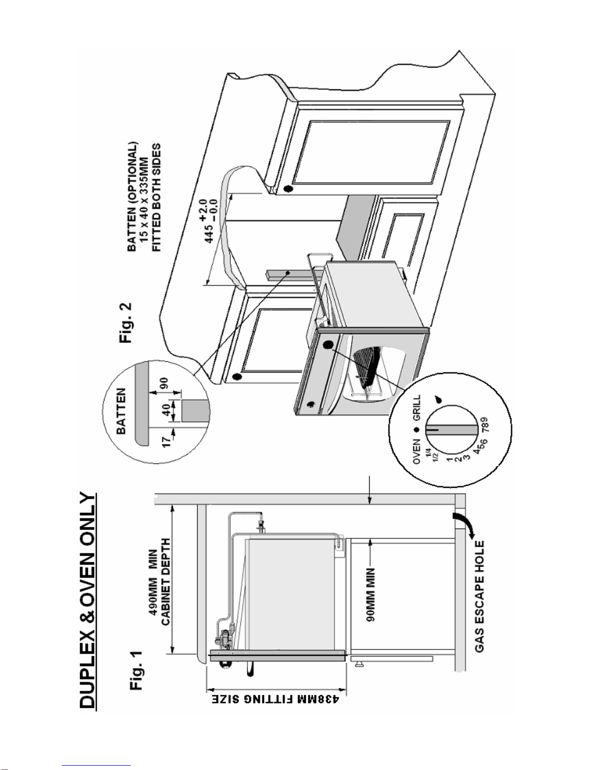
2. To light: Open door, push in the control knob and turn to full rate – see Fig 2. Hold a
lighted match or taper to the burner and push the control knob in and hold. The burner
should ignite and the control knob should be held in for 10 -15 seconds before release.
If the burner goes out, repeat procedure holding control knob for slightly longer.
3. For models fitted with Spark Ignition the procedure is similar except that the burner can
be ignited by depressing the ignition button, which is located on the fascia. Ignition
must be carried out with the door open, and if the burner has not lit within 15 seconds
the control knob should be released and the grill left for at least 1 minute before a
further attempt to ignite the burner.
4. Note: the grill must only be used with the door open.
5. On first use of the grill, it should be heated for about 20 minutes to eliminate any
residual factory lubricants that might impart unpleasant smells to the food being
cooked. A non-toxic smoke may occur when using for the first time so open any
windows and turn on mechanical ventilators to help remove the smoke.
6. Although the grill does heat up quickly, it is recommended that a few minutes preheat
be allowed.
7. Flame Failure Device (FFD): the grill burner is fitted with a flame sensing probe, which
will automatically cut off the gas supply in the event of the flame going out. In the event
of the burner flames being accidentally extinguished, turn off the burner control and do
not attempt to re-ignite the burner for at least one minute.
8. It is normal for the flames on this burner to develop yellow tips as it heats up,
particularly on Butane.
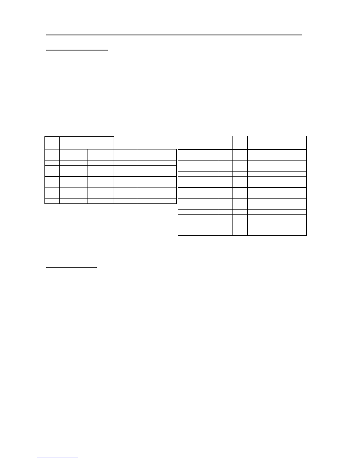
9. A reversible grill pan trivet enables the correct grilling height to be achieved.
Fast Toasting trivet in high position
Grilling Sausages trivet in high position
Grilling Steak/Bacon trivet in high position
Grilling Chops, etc trivet in low position
Slow Grilling trivet removed
10.To turn off: turn the control knob until the line on the control knob is aligned with the dot on
the control panel. Always make sure the control knob is in the off position when you have
finished grilling
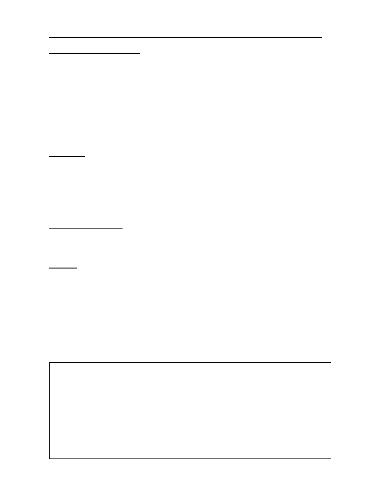
IMPORTANT
•The control tap on this appliance operates both the Grill and Oven
burners. To ensure safe operation it is not possible to operate both
burners at the same time.
•The pan supplied with the appliance is multi functional, for use either
whilst grilling or when using the oven. The handle design allows removal
or insertion whilst the pan is in use. Always remove the handle when the
pan is in use.
5