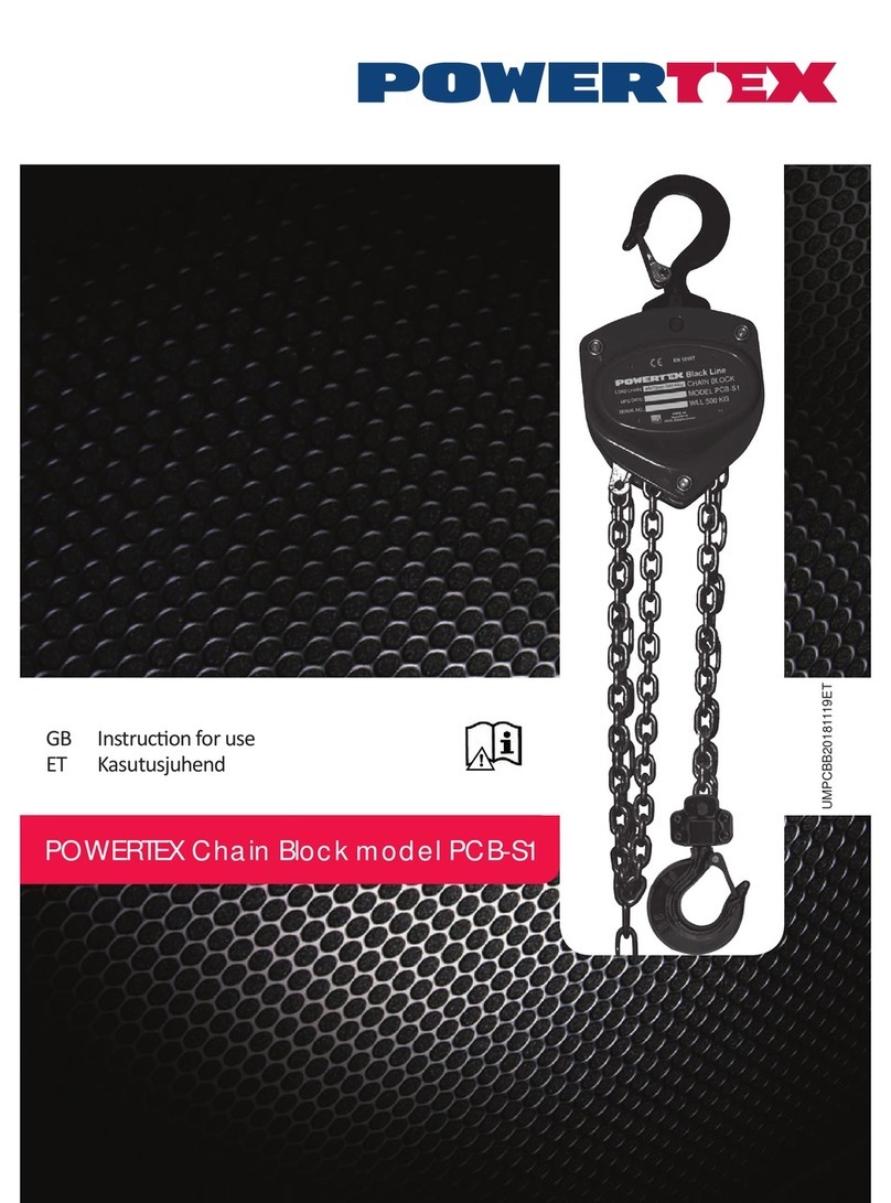
Thiele TM Series User manual

Art.-No.: B07725-F - 1 / 9 - Edition: EN-100415
M A N U A L
TM - Chain Blocks
Original operating instructions in keeping
with the EC Machinery Directive
TM-B-OP-05N TM-B-OP-30N
TM-B-OP-10N TM-B-OP-50N
TM-B-OP-20N TM-B-OP-100N
# Marking of changes to prior edition
TM chain blocks meet requirements as per EU Machinery Directive 2006/42/EG and
were type tested by a certification body (TÜV Rheinland inspection agency).
Read this manual before using the TM Chain Block.
This manual includes very important information concerning safety and operation.
Warning Note
TM - Chain Blocks are not intended for lifting, carrying or transporting of persons
and thus must not used for this purpose!
Death or injury can occur from improper use or maintenance.

Art.-No.: B07725-F - 2 / 9 - Edition: EN-100415
1 General features
TM chain blocks are inter alia employed in the construction industry, in mining opera-
tions, marine applications and other sectors of industry.
Significant characteristics are:
Overload protection
Automatic, double-pawl braking system
Stainless steel load chain to EN 818-7, type T, electrogalvanized
2 Safety Notes
The subsequent safety information provides an overview of the general methods of ac-
tion in order to safely operate TM manual chain blocks. Disregard of these safety notes
may result in death, severe injury or damage to property. Instructions hereunder are not
to be considered exhaustive and are thus not limited to the following.
1. Only persons who received safety instructions and have been trained in the opera-
tion of the equipment are allowed to use the chain block.
2. In addition to the operating instructions, operators must be aware of and have
been appropriately trained with regard to the relevant accident prevention regula-
tions "Load-carrying devices used with lifting equipment", BGR 500. Only author-
ised persons in accordance with BGR 500, Chapter 2.8 may be assigned to per-
form assembly and dismantling work.
3. Check whether the suspension points are able to assume the forces to be applied.
4. Structural modifications, attachments or conversions are not permitted.
5. Do not operate or use chain blocks showing wear, damage or improperly function-
ing hook safety latches.
6. Inspect and check the chain block at regular intervals.
7. Replace worn and/or damaged parts.
8. Lubricate movable parts and the chain at regular intervals. Make sure to remove
lubricants and dirt from the braking surfaces inside the block housing.
9. Never connect the chain ends in an inadmissible manner.
10. Do not lift loads of a weight higher than what has been prescribed as load capacity
for the chain block (see section “Technical Details” in this respect).
11. If simultaneously lifting a load by means of two chain blocks, the load capacity of
each of the two blocks must at least be equal to the weight of the load.
12. Loads must be attached in accordance with BGI 556 –"Government safety asso-
ciation information for load attachment personnel".
13. The chain must not wrap around the load or other components.
14. Position the chain block vertically above the load’s center of gravity. Never ‘drag’
or ‘pull’ the load sideways.
15. The operational rotation of the load in the hook or the rotation of the chain block in
the suspension hook is not permitted.
16. Never operate a hoist the chain of which is twisted, has kinks, is elongated or oth-
erwise damaged.
17. Make sure the load is fully supported by and has contact with the hook bed and the
safety latch has engaged.
18. Do not support any load with the tip of the hook.
19. Do not run the chain over edges.
20. During hoisting operation always observe the load.
21. Always make sure no one including you (operator) is in the range of the moving
load (hazard area) and do not lift any load over people.

Art.-No.: B07725-F - 3 / 9 - Edition: EN-100415
22. Do not lift any load over people.
23. When lifting a load start with tightening the chain slowly.
24. Do not lift the load jerkily.
25. Never cause a suspended load to swing.
26. Never leave a suspended load unattended.
27. Welding or cutting work must not be performed on a lifted load.
28. Never use a hoist chain in connection with welding work.
29. Stop operation of the chain block when unusual noise is heard, or if chain jumping
or jamming occurs.
30. Only operate the chain block manually.
31. After use or in the event the chain block is inoperative make sure it has been se-
cured to prevent unauthorized or inadmissible use.
32. Do not remove or cover warning labels located on the device.
33. Do not clean chain blocks with water or with a high-pressure cleaner.
34. Do not use chain blocks to lift dangerous goods such as molten or radioactive ma-
terials.
35. Operating temperature range is between -10 °C and +50 °C.
36. The brake must be examined for icing in the event of operating temperatures be-
low 3 °C.
37. The brake pads may overheat when constantly lowering when dealing with long
hook paths (> 3m). Ensure that cooling pauses are taken.
38. Storage temperature range is between 0 °C and +40 °C.
39. Observe national regulations that may not be stated here.
3 Pre –installation inspections
Prior to commissioning (first use) the user should observe any applicable local or other
provisions relating to the specific operation of the chain block.
Before using the chain block for the first time read this operating manual as well as any
labels supplied with or attached to the hoist to rule out the equipment is operated im-
properly. Further points to be observed:
Before using it, visually inspect the chain block carefully to detect transportation
damage, if any.
Ensure that a functional and visual inspection is performed by an expert.
In case of a used chain block check the equipment’s service history and any doc-
umentation provided.
Lubricate the load chain of the hoist prior to commissioning.
Ensure that testing intervals and the next testing date is determined. A notification
regarding the next test must be attached to the manual chain block.
Dispose packing in accordance to local regulations.
After hanging the chain block, position the lower end of the hand chain at a height of
500-1000 mm from the floor. In order to complete this task, you may have to shorten the
hand chain by laterally bending the non-welded connecting link open, shortening the
hand chain respectively and bending the connecting link closed.
Normal chain links are not suitable for use as a connecting link.
4 Operating instructions
Check the load brake for proper functioning by first raising the load and keeping it in that
position. Position the chain block between the load to be lifted and the suspension point

Art.-No.: B07725-F - 4 / 9 - Edition: EN-100415
in the load’s center of gravity. Ensure hooks are seated correctly and the safety latches
are engaged.
Also make sure that chains and hooks are not twisted, knotted or have cracks.
Lifting the load:
Ensure that there are no people or obstructions in the immediate area of the moving
load. Begin lifting by slowly pulling the hand chain in „U“(up) direction.
Lowering the load:
Ensure that there are no people or obstructions in the immediate area of the moving
load. Lower the load by pulling the hand chain in „D“ (down) direction. For releasing the
brake disk a little more force may be needed.
After use:
Remove any foreign objects and dirt from the chain and hoist. Inspect chains, hooks and
the safety latches to ensure they are operational. When unused, store the chain block in
a dry and clean location.
Slip clutch:
The slip clutch is set to approx. 1.6 x WLL at the factory and exclusively serves to pro-
vide the chain block an overload protection. It may not be operationally used or actuat-
ed. The slip clutch must exclusively be adjusted/set by manufacturer or authorized com-
petent persons. Repeated checks of the slip clutch setting at short intervals (e.g. after it
has been hired out) are not permissible.
5 Load chain mounting
1. Clean the chain that is to be assembled as well as the parts of the chain block that
come into contact with the chain.
2. Insert the first chain link in an upright position (vertical to the sprocket) between
the chain guide and the sprocket. Ensure that the welding seams of the follow-
ing vertical chain links point outwards in a radial manner. Rotate the hand
wheel so that the second chain link can be horizontally assumed by the following
pocket of the sprocket.
3. Continue with the rotary movements until sufficient chain links protrude from the
other side of the housing in order to perform the further steps.
4. Pay attention to the correct positioning of both chain strands in terms of the chain
guide rollers. During operation, the housing orients itself according to the
load. Neither of the chain strands may then come into contact with the hous-
ing bolts under load. The chain may not run above the guide roller under any
circumstances.
5. When dealing with a single-strand design, insert the chain end of the load strand
into the console of the hook attachment and fasten it with the chain bolt. Secure
chain bolt with new self-locking nuts.
6. When dealing with a twin-strand design, insert the chain end of the load strand
above the bottom block sprocket. In doing so, pay attention to the correct align-
ment of the inlet to the chain drive sprocket so that the chain strand is not twisted.
7. When dealing with the TM-B-OP-100, insert the chain end of the of the load strand
via the sprockets of the bottom and top block according to the reeving diagram il-
lustrated on the next page. In doing so, pay attention to the correct alignment of
the inlets to the chain drive sprocket so that the chain strands are not twisted.
8. Fasten the loose chain to the chain end fitting fixed to the housing. In the event of
a twin-strand reeving the loose chain end coming out of the bottom block will be

Art.-No.: B07725-F - 5 / 9 - Edition: EN-100415
fixed by a bolt to the upper hook suspension. Pay attention that the chain strands
are not twisted. If necessary, shorten the chain by removing a link. Secure the
chain bolt with a new splint.
9. Perform a functional test using a low load. Check that the chain strands are not
twisted, that the chain is not touching the housing bolts and that it flawlessly glides
into the chain guide.
Reeving of Load Chain - TM-B-OP-100N:
For chain mounting make sure that the welds of the upright chain links in the
sprockets of the drive module and top block face outwardly!
For design reasons, at the bottom block this can only be achieved by a deflector roll.
The load chain must not be twisted between its two attachment ends.
6 Inspection and tests
Prior to use the operating personnel or maintenance staff must visually check the chain
block for damage or incorrect functioning.
Operation:
Watch out for damage or abnormal noise that may be the result of potential problems.
Do not use the chain block when the load chain cannot run freely through the blocks.
Listen for clicking and pay attention to any blocking or malfunction. The clicking sound of
the pawl of the ratchet is normal when a load is lifted. If a chain jams, jumps or in case
excessive noise can be heard check the chain carefully.
Make sure the hand chain moves freely without jamming and is not damaged.
If any problem is permanent return the chain block to one of the service addresses for
inspection and/or repair.
Do not operate the chain block until all problems are solved.
Drive module
Top block
Bottom block
Hand chain

Art.-No.: B07725-F - 6 / 9 - Edition: EN-100415
Diameter
Welded area
Wear in these
areas
Load chain:
Check all chain links for bending, cracks, and notch-
es, pitting, and wear.
The chain should be taken out of service if the pitch
has increased by more than 3 % or the average wire
diameter reduced by more than 10 %.
Check for correct chain lubrication and re-lubricate if
necessary. If the chain is dirty and unlubricated, this
can lead to premature wear and subsequent chain
failure. Lubricate the chain, e.g. with a mineral oil in
accordance with DIN 51502 CLP 220 or with a dry lubricant, e.g. Unimoly C 220 Spray
in the event of a dusty or dirty environment.
Hooks:
Check hooks for wear and damage. Take hooks out of service if the hook opening has
widened by more than 10 % or the shank height in the hook bed reduced by more than
5 % compared to a new hook. In the event a safety latch does not correctly engage with
the hook tip this is due to overloading and the respective hoist must be replaced. Check
whether the hooks swivel smoothly. Check the safety latch for proper functioning.
Slipping clutch:
If the device is used as intended, the slipping clutch is not set or adjusted. It can only be
replaced as a complete unit and must be subsequently examined by expert staff once
installed.
Transmission:
The transmission is maintenance-free.
Tests and maintenance work must be arranged by the user.
The chain block shall be checked by an authorized repair center at least once a year.
An inspection documentation must be prepared for each hoist and all inspection activi-
ties must be included in that service history.
The chain block must be recertified after 4 years of operation at the latest. Such a recer-
tification must also be performed after the chain block has been repaired with such a
repair to be carried out by an authorized repair center. In this case contact one of the
service addresses listed in this manual.
7 Maintenance and repair
The repair of a chain block must exclusively be performed by a service workshop au-
thorized by THIELE. In this case please refer to one of the service addresses.
Replacing the chain:
Relieve the chain block of load and loosen the chain bolt on the hook tackle or suspen-
sion console in the event of a twin-strand reeving as well as on the chain end fitting. Al-
low the used chain to run through the chain block in the lifting or lowering device and, if
necessary, pull the chain through the top and bottom block. Assemble the new chain
according to the information provided in Chapter 5.
Replacing the load hook / hook tackle (single-strand):

Art.-No.: B07725-F - 7 / 9 - Edition: EN-100415
The hook tackle can only be replaced as a unit. Relieve the chain block of load and
open the nut belonging to the chain bolt. Pull the chain bolt out of the hook tackle con-
sole. Insert the chain end into the console of the new hook tackle and push a new chain
bolt into the drill hole of the console and through the last chain link. Secure the chain
bolt with a new self-locking nut.
Replacing the load hook / bottom block (twin-strand):
Relieve the chain block of load and open the screw belonging to the bottom block con-
sole. Open one half of the bottom block console and remove the hook. Correctly insert
the new hook complete with its retainer into the bottom block console. Close the bottom
block console with its half. In doing so, ensure that the hook retainer and the sprocket
bolts are located in the intended retainers.
Re-insert the screws and secure them with new self-locking nuts.
Replacing the suspension hook:
The housing must be opened in order to replace the suspension hook. Therefore, this
work should only be performed by an authorized expert. In such a case, please contact
a service address.
Dispose:#
Nearly all parts are made of steel and should be scrapped in accordance to local regula-
tions.
THIELE GmbH & Co. KG will not assume any responsibility for failures or damage that may result from a non
appropriate use of the products or a non-observance of the product documentations.
Copyright on this documentation remains with THIELE GmbH & Co. KG. Any use not authorized by the copyright
owner (e.g. reproduction) is liable to prosecution and gives rise to damages claims.

Art.-No.: B07725-F - 8 / 9 - Edition: EN-100415
8 Spare parts
Item
Description
Item
Description
Item.
Description
1
Gearbox cover
19
Hand chain wheel
37
Ball bearing, hook
2
Housing plate, gear side
20
Hand chain
38
Hook nut
3
Housing plate, handwheel
21
Housing cover, handwheel
39
Sprocket, top/bottom block
4
Gearwheel stage
22
Hex. nut, self-locking
40
Needle bearing, sprocket
5
Sprocket, complete
23
Guide roll
41
Bracket, hook suspension
6
Suspension hook
24
Scraper
42
Bolt
7
Safety latch, complete
25
Chain
43
Hook pin
8
Hook
26
Pin
44
Sprocket pin
9
Drive shaft
27
Chain end fitting
45
Suspension plate
10
Safety ring
28
Pin, chain end fitting
46
Bracket, bottom block
11
Gearwheel
29
Cotter pin
55
Hex. nut, slip clutch
12
Pin
30
Slotted nut
56
Cup spring, slip clutch
13
Pawl spring
31
Hook, 2-strand
57
Thrust disk, slip clutch
14
Pawl
32
Sprocket, bottom block
58
Friction lining
15
Brake hub
33
Pin, bottom block
59
Hand chain whel
16
Brake lining
34
Bracket, bottom block
60
Pawl, slip clutch
17
Ratched disk
35
Hex. Bolt
61
Thrust disk, brake
18
Housing cover, inside
36
Bracket, susp. hook
62
Circlip, slip clutch
When ordering spare parts please indicate the model and serial No. of the chain block.

Art.-No.: B07725-F - 9 / 9 - Edition: EN-100415
Article-no. spare parts
Type TM-B-OP-…
Item
Description
…05N
…10N
…20N
…30N
…50N
6
Suspension hook
Z09939
Z09940
Z09941
Z09942
Z09943
7
Safety latch, complete
Z09944
Z09945
Z09946
Z09947
Z09948
8
Hook
Z09949
Z09950
Z09951
Z09952
Z09953
16
Brake lining
Z06934
Z06935
Z06936
Z06937
Z06938
17
Ratched disk
Z06928
Z06929
Z06930
Z06931
Z06932
25
Chain (sold by meter)
F09027
F09047
F09057
Please direct your inquiries to the service address for the TM-B-OP-100N spare parts.
9 Technical details
Model/Type ►
TM-B-OP-05N
TM-B-OP-10N
TM-B-OP-20N
TM-B-OP-30N
TM-B-OP-50N
TM-B-OP-100N
Capacity (WLL) [t]
0,5
1
2
3
5
10
Standard lift [m]
2,5#
2,5#
3
3
3
3
Pull force at hand chain with
full capacity [N]
230#
360#
430#
440#
470#
480#
Max. force transmission until
the activation of the over-
load protection
0,96
1,92
3,84
5,76
9,6
19,2
Min. distance between
hooks [mm]
270
317
414
465
636
798
Load chain dia. [mm]
6
6
8
8
10
10
Net weight [kg]
8,1#
10,7#
17,7#
24#
38,6#
80,4#
Packing dimensions
L x W x H [cm]
25 x 20 x 17
30 x 24 x 17
35 x 26 x 19
39 x 28 x 19
46 x 32 x 21
50x41x21
Additional weight for special
chain lengths [kg/m]
0,9
1
1,2
2,4
4,6
9,2
10 Service address
THIELE GmbH & Co. KG, Postfach 8040, 58618 Iserlohn, Tel. +49(0)2371/947-0
11 Warranty
For TM chain blocks, a one-year warranty is granted from the date of purchase for de-
fective materials or executions. Wear parts as well as parts that have been overloaded
and incorrectly used are excluded from the warranty.
In the event of a justified complaint, the girder clamp will be repaired or replaced.
12 Documentation
TM Chain Blocks will be supplied with this manual and with an acceptance test certifi-
cate with a Declaration of Conformity.
This manual suits for next models
6
Other Thiele Lifting System manuals
Popular Lifting System manuals by other brands
VOGELS
VOGELS PPL 2500 installation manual
Tommy Gate
Tommy Gate V2 Series Owner's and operator's manual

Braun
Braun CENTURY NCL 06 Series Service manual
Tractel
Tractel T 1000 Original Operation and Installation Manual
Porta-Dock
Porta-Dock 1265V instructions

Vestil
Vestil SLNM Series Operation and maintenance manual
Braun
Braun NCL Century 2 Series manual
AMGO Hydraulics
AMGO Hydraulics PRO-12 Installation and service manual
Snorkel
Snorkel S39770RT Repair parts manual

Ergotron
Ergotron StyleView SV22 Assembly instructions
Ravaglioli
Ravaglioli KPN345WE Translation of the original instructions

Omega Lift
Omega Lift 23225 user manual
