Thiele TWN 1884 User manual
OPERATING INSTRUCTIONS
LIFTING POINTS „XKE-POINTS“
TWN 1884
THIELE GmbH & Co. KG # Change indicator
www.thiele.de | info@thiele.de 12239-A replaces -
© All rights reserved EN 03.2023 1 | 4
Original in compliance with machinery directive 2006/42/EC
1DESCRIPTION AND INDENTED USE
THIELE screw-type lifting points “XKE-Points” are intended to securely connect
components/loads with slings, e.g. with chain slings according to EN 818-4 or with
lashings according to EN 12195.
They are intended for installation in steel, aluminium or non-ferrous component
constructions.
The “XKE-Points” meet EC Machinery Directive 2006/42/EC requirements and feature
a safety factor of at least 4 based on the working load limit (WLL).
The „XKE-Points“ are marked with the CE symbol. They are also marked with the
working load limit in tons, the thread size, manufacturers mark “H4” and traceability
code.
The „XKE-Points“ are designed to withstand 20 000 dynamic load changes under
maximum load conditions. In the event of higher loads (e.g. multi-shift/automatic
operation) the working load limit must be reduced.
The „XKE-Points“ must exclusively be used
•within the limits of their permissible working load limit,
•within the temperature limits prescribed,
•with suitable screws (see screw data) and fitted directly to the component.
The working load limits depending on the number of legs and inclination angles are
shown in the table in chapter 4.2.
The lifting points are normally not intended for the transportation of persons.
The occasional turning and rotating of loads is permitted. The permanent turning and
rotating of loads is not permitted.
Using the lifting points exclusively for lashing the lashing capacity (LC) is calculated by
doubling the working load limit.
An alternating use for lifting and lashing is not allowed.
2SAFETY NOTES
Risk of injury!
Never walk or stay under lifted loads!
Make sure to use hoisting/attachment means
free from defects.
•Operators, fitters, and maintenance personnel must in particular observe the
operating instructions also from the used sling chain assemblies, documentations
DGUV V 1, DGUV R 109-017 and DGUV I 209-013 issued by the German Employers’
Liability Insurance Association (DGUV), as well as the operating instructions of the
loads concerning advise for lifting.
•In the Federal Republic of Germany, the Operational Safety Ordinance ( etrSichV)
has to be implemented and the Technical Rule for Industrial Safety TR S 1201, in
particular annex 1, chapter 2 "Special regulations for the use of working equipment
for lifting loads" must be observed.
•Outside the Federal Republic of Germany the specific provisions issued locally in
the country where the items are used must also be observed.
•The directions given in these operating instructions and specified documentations
relating to safety, assembly, operation, inspection, and maintenance must be made
available to the respective persons.
•Make sure these operating instructions are available in a place near the product
during the time the equipment is used. Please contact the manufacturer if
replacements are needed. See also chapter 11.
•When performing work make sure to wear your personal protective equipment!
•Improper assembly and use may cause personal injury and/or damage to
property.
•Assembly and removal as well as inspection and maintenance must exclusively be
carried out by skilled and authorized persons.
•efore each use, check that the upper parts of the lifting points can be turned
easily and that the turning movement does not occur in the screw connection!
•Operators must carry out a visual inspection and, if necessary, a functional test of
the safety equipment before each use.
•Never install more than one fastener to a lifting point.
•Structural changes are impermissible (e.g. welding, bending).
•Never use worn-out, bent or damaged lifting points.
•Only lift loads the mass of which is less than or equal to the working load limit of
the lifting points.
•Do not use force when mounting/positioning the lifting points.
•Only lift loads that are freely movable and not attached or fastened.
•Do not start lifting before you have made sure the load has been correctly attached.
•Make sure no one including you (operator) is in the way of the moving load (hazard
area).
•During lifting/hoisting make sure your hands or other body parts do not come into
contact with hoisting means. Only remove hoisting means manually (use your
hands).
•Avoid impacts, e.g. due to abruptly lifting loads with chain in slack condition.
•Never move a suspended load over persons.
•Never cause suspended loads to swing.
•Always monitor a suspended load.
•Put the load only down in flat places/sites where it can be safely deposited.
•Take care for sufficient place for the personnel to move when choosing the route
of transportation and storage location. Danger to life and risk of injury by crushing
hazards!
•In the event of doubts about the use, inspection, maintenance or similar things
contact your safety officer or the manufacturer.
THIELE will not be responsible for damage caused through non-observance of the
instructions, rules, standards and notes indicated!
Working under the influence of drugs, medications impairing the sense and/or
alcohol is strictly forbidden!
3COMMISSIONING
Prior to using the lifting points for the first time make sure that
•the lifting points comply with the order and have not been damaged,
•test certificate, statement of compliance, and operating instructions are at hand,
•markings correspond with what is specified in the documentation,
•inspection deadlines and the qualified persons for examinations are determined,
•visibility and functional testing are carried out and documented,
•documentations are safely kept in an orderly manner.
Dispose of the packing in an environmentally compatible way according to local rules.
OPERATING INSTRUCTIONS
LIFTING POINTS „XKE-POINTS“
TWN 1884
THIELE GmbH & Co. KG # Change indicator
www.thiele.de | info@thiele.de 12239-A replaces -
© All rights reserved EN 03.2023 2 | 4
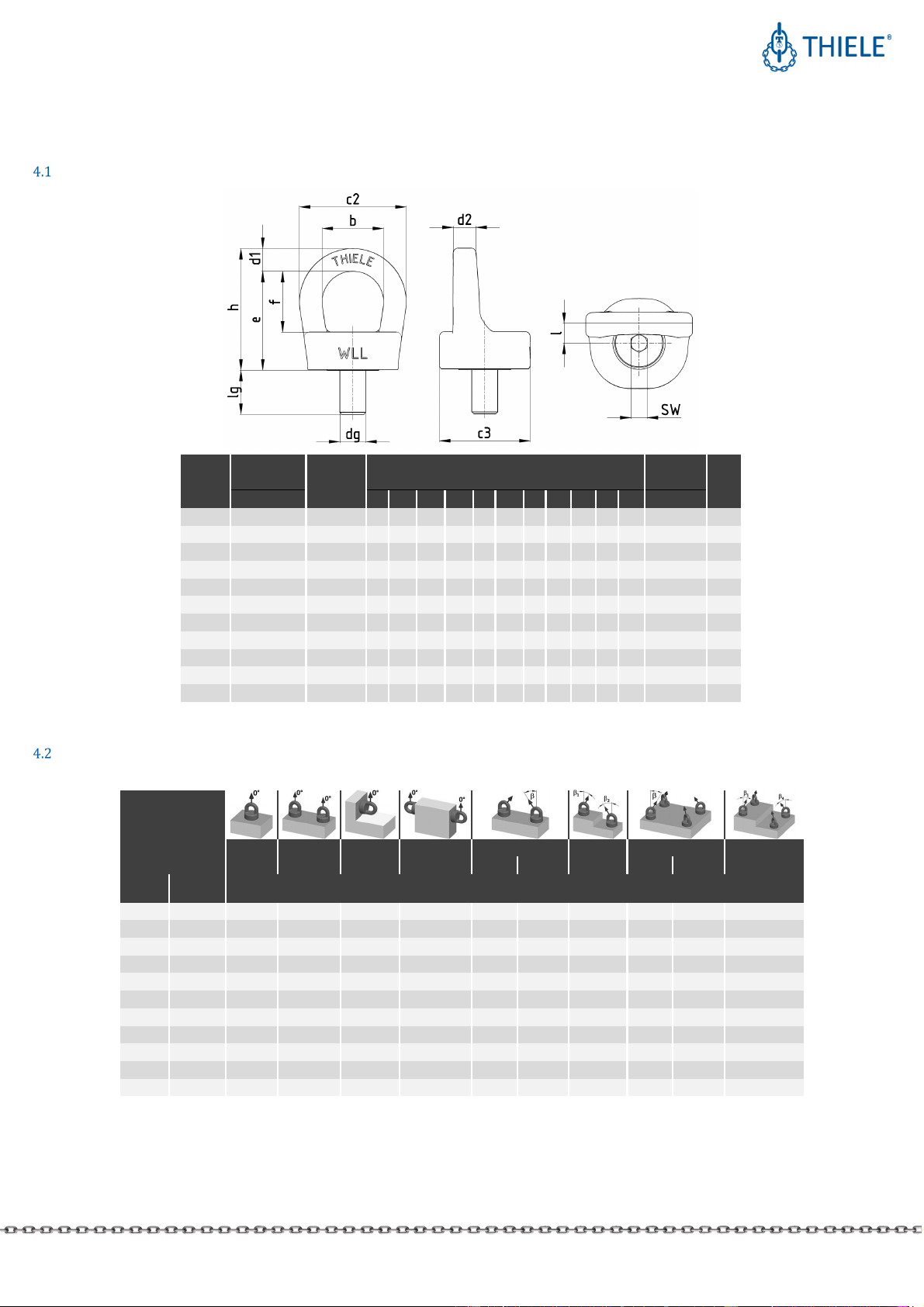
4TECHNICAL DATA
Dimen ion
Thread
size
Working load
limit (WLL) Article no.
Dimensions [mm] Tightening
torque
1)
Mass
dg [mm]
[t] b c2 c3
e
f
h lg d1
d2
l SW
[Nm] [kg]
M 8 0,3 F38005 26
45 37 40 26
50 16
9,5
9,5
8 6 13 0,18
M 10 0,5 F38006 26
45 37 40 26
50 16
9,5
9,5
8 6 25 0,18
M 12 1,0 F38007 30
51 43 47 30
57 18
11 11 10
8 40 0,29
M 16 1,7 F38010 38
66 56 62 38
76 27
14 14 13
10 90 0,66
M 20 2,6 F38020 42
74 61 70 42
86 33
16 16 15
12 170 0,99
M 24 3,5 F38030 51
85 65 82 51
99 39
17 18 16
14 280 1,34
M 30 6,0 F38040 62
104
82 97 62
118
45
21 22 20
19 550 2,29
M 36 8,0 F38050 75
131
92 116
75
144
55
28 28 25
19 900 4,18
M 42 11,5
F38060 95
173
122
142
95
181
64
39 39 33
22 1 400 8,89
M 45 13,0
F38070 95
173
122
142
95
181
74
39 39 33
24 1 600 9,12
M 48 14,5
F38080 95
173
122
142
95
181
74
39 39 33
27 1 900 9,21
1) See chapter 5.2
Working load limit (WLL) depending on number of leg (lifting point ) and inclination angle
Attachment type
Number of legs 1-Leg 2-Leg 1-Leg 2-Leg 2-Leg 2-Leg 3-/4-Leg 3-/4-Leg
Inclination angle β
0°
±5°
0°
±5°
0°
±5°
0°
±5°
0°- 45° 45°- 60° asym.
2)
0°- 45° 45°- 60° asym.
2)
WLL
[t]
Thread
[mm] MAXIMUM TOTAL LOAD [t]
3)
0,3 M 8 0,3 0,6 0,3 0,6 0,4 0,3 0,3 0,6 0,45 0,3
0,5 M 10 0,5 1,0 0,5 1,0 0,7 0,5 0,5 1,0 0,75 0,5
1,0 M 12 1,0 2,0 1,0
2,0
1,4 1,0
1,0
2,1 1,5 1,0
1,7 M 16 1,7 3,4 1,7 3,4 2,4 1,7 1,7 3,6 2,5 1,7
2,6 M 20 2,6 5,2 2,6 5,2 3,6 2,6 2,6 5,5 3,9 2,6
3,5 M 24 3,5 7,0 3,5 7,0 4,9 3,5 3,5 7,4 5,2 3,5
6,0 M 30 6,0 12,0 6,0 12,0 8,4 6,0 6,0 12,7 9,0 6,0
8,0 M 36 8,0 16,0 8,0 16,0 11,3 8,0 8,0 16,9 12,0 8,0
11,5 M 42 11,5 23,0 11,5
23,0
16,2 11,5
11,5
24,3 17,2 11,5
13,0 M 45 13,0 26,0 13,0 26,0 18,3 13,0 13,0 27,5 19,5 13,0
14,5 M 48 14,5 29,0 14,5 29,0 20,5 14,5 14,5 30,7 21,7 14,5
2) Reduced working load limits according to DIN 685-5
3) Without consideration of further lifting means

OPERATING INSTRUCTIONS
LIFTING POINTS „XKE-POINTS“
TWN 1884
THIELE GmbH & Co. KG # Change indicator
www.thiele.de | info@thiele.de 12239-A replaces -
© All rights reserved EN 03.2023 3 | 4
5ASSEM LY AND REMOVAL
Preparation
The mounting location for each lifting point must ensure that
•the load can take the forces safely to be applied without suffering deformation,
•the lifting point can be assembled flush,
•no areas of danger are created (crushing point, shearing point),
•transportation is not restrained by overhang,
•deflections of sling components are avoided,
•incorrect use is avoided,
•the sling cannot be damaged, for example by sharp edges,
•the lifting point can be used easily.
A embly
The useful depth of the thread must enable the lifting points to be safely screwed in.
Use only the delivered screws!
The threaded hole must be perpendicular to the screw-on surface in the load. The
depth of the thread "L" of the component must be at least as follows:
L = 1,0 x dg for steel (yield stress R
e
≥ 235 N/mm²)
L = 1,25 x dg for castings
L = 2,0 x dg for aluminium
L = 2,5 x dg in aluminium-magnesium-alloys
(L = depth of thread; dg = thread diameter)
•Make sure the threads of the lifting point and in the component are clean and dry.
•If lifting points should remain on the component a thread locker has to be used.
•For through-boltings, the nut must be secured against loosening.
•Single lifting operation WITHOUT turning or rotating:
Hand-tighten the screws with a suitable spanner for screws with hexagon socket
according to DIN.
It must be ensured that the screws of the lifting points cannot loosen by themselves.
•Lifting WITH turning or rotating as well as multiple lifting operations:
Tighten the screws to the tightening torques specified in the technical data.
However, repeated lowering of the load to the ground requires a new check!
•Lifting points that remain on the loads should be tightened to the tightening torques
specified in the technical data.
•Chamfers on the threaded holes are not required.
6USE IF DIFFERENT SCREWS
If local circumstances dictate that different screws must be used from those supplied
with the installation or listed in chapter 9, the operator must ensure that
•these fasteners conform to the specified diameter and strength class,
•they can achieve the minimum required screw-in depth,
•they are 100 % crack tested,
•each bolt has a proven notched impact energy of min. 36 J as a mean value of three
samples tested at -20 °C or at the lowest fitting temperature, if this is below -20 °C,
and that none of the samples fall below 25 J,
•written confirmation of the crack test and impact energy results is enclosed with the
technical documentation.
7CONDITIONS OF USE
Normal u e
The force must be applied in the longitudinal direction of the attached component (e.g.
hook).
The attached component (e.g. hook) must always be able to move freely. Supporting
the component at the lifting point is not permissible.
Using 4-leg chain slings may cause higher risk because only 2 opposite legs carrying the
load. Check the working load limit of lifting points and chain sling carefully and chose if
necessary bigger sizes.
The following illustrations show typical applications and foreseeable misuse:
U e in through hole
If lifting points are fastened by means of nuts in holes (e.g. of metal sheets), the
following conditions must be observed:
•Turning or rotating the load is not permitted.
•The strength class of the nuts must be 10 or higher (thread size M12: class 12).
•The chamfer at the end of the screw thread must protrude from the nut.
•It must be ensured that the component to be lifted is suitable to withstand the force
to be applied safely and without deformation, including the corresponding safety
factors.
•Suitable action must be taken to ensure that the nut cannot loosen unintentionally,
e.g. suitable torque or threadlocker.
Influence of temperature
The permissible working load limit of the lifting points reduces at elevated
temperatures. The reduced working load limit figures shown in the following table shall
only apply for short-term use at the temperatures indicated.
Temperature range Remaining working load limit (WLL)
-20 °C ≤ t ≤ 100 °C 100 %
100 °C < t ≤ 200 °C 85 %
200 °C < t ≤ 250 °C 80 %
250 °C < t ≤ 300 °C 75 %
If a lifting point has been exposed to temperatures exceeding the maximum values
specified, it must no longer be used.
Use below -40 °C is generally not permitted.
Take care for a loss of lubricant depending on several fitting positions and higher
temperatures. A higher wear may occur. Shorten the inspection interval for that case.
OPERATING INSTRUCTIONS
LIFTING POINTS „XKE-POINTS“
TWN 1884
THIELE GmbH & Co. KG # Change indicator
www.thiele.de | info@thiele.de 12239-A replaces -
© All rights reserved EN 03.2023 4 | 4
Environmental influence
Lifting points must not be used in environments where acids, aggressive or corrosive
chemicals or their fumes are present.
Hot-dip galvanizing or a galvanic treatment is prohibited as well.
8INSPECTIONS, MAINTENANCE AND DISPOSAL
General
Inspections and maintenance must be arranged for by the owner!
Inspection deadlines shall be determined by the owner!
Inspections must be carried out and documented by competent persons regularly but
at least once a year, or more frequently if the lifting points are in heavy-duty service.
After three years at the latest they must additionally be examined for cracks. A load
test shall never be considered a substitute for this examination.
The results of the inspection shall be entered into a register (DGUV I 209-062 or
DGUV I 209-063) to be prepared when a lifting point is firstly used. The register will
show characteristic data of the lifting points and other components as well as identity
details.
Immediately stop using lifting points that show the following defects:
•missing or illegible identification/marking
•deformation, elongation or fractures
•cuts, notches, cracks, incipient cracks, pinching
•limited rotatability (dry or stuck ball bearing)
•heating beyond permissible limits
•severe corrosion
•defect screw or thread
In pection ervice
THIELE offers inspection, maintenance and repair services for lifting points performed
by trained and competent personnel.
Maintenance
Maintenance and repair work must only be performed by competent persons.
Minor notches and cracks at suspension links may be eliminated by careful grinding
observing the maximum cross section reduction requirement of 10 % and avoid making
more severe cuts or scores.
Regreasing of the ball bearing is not intended. Replace lifting points with recognisably
dry ball bearings.
All maintenance and repair activities are to be documented.
Di po al
All components and accessories of steel taken out of service are to be scrapped in line
with local regulations and provisions.
9SPARE PARTS
Only use original THIELE spare parts. Exclusively use original THIELE screws, because
these are made to meet special requirements.
Thread size Article no. Screw data
M 8 Z11727 DIN 7991 M8 x 30 10.9
M 10 Z11728 DIN 7991 M10 x 30 10.9
M 12 Z11681 DIN 7991 M12 x 35 12.9
M 16 Z10869 DIN 7991 M16 x 50 10.9
M 20 Z11200 DIN 7991 M20 x 60 10.9
M 24 Z11199 DIN 7991 M24 x 70 10.9
M 30 Z11722 DIN 7991 M30 x 80 10.9
M 36 Z11747 DIN 7991 M36 x 100 10.9
M 42 Z11804 DIN 7991 M42 x 110 10.9
M 45 Z11805 DIN 7991 M45 x 120 10.9
M 48 Z11806 DIN 7991 M48 x 120 10.9
10 STORAGE
Lifting points have to be stored in dry locations at temperatures ranging between 0 °C
and +40 °C.
11 THIELE OPERATING AND MOUNTING INSTRUCTIONS
Current operating and mounting instructions are available as a PDF download on the
homepage.
12 IMPRINT
THIELE GmbH & Co. KG
Werkstrasse 3
58640 Iserlohn, Germany
Tel.: +49(0)2371/947-0
Email: info@thiele.de
13 DECLARATION OF CONFORMITIY
EC-DECLARATION OF CONFORMITY
acc. to Machinery Directive 2006/42/EG, Annex II A for a machine
THIELE GmbH & Co. KG herewith declares as manufacturer that the products
Lifting points „XKE-Points“, TWN 1884
are placed on the market in the form of a complete machine by THIELE together with
the relevant test certificate and are in compliance with the applicable provisions of the
CE Machinery Directive 2006/42/CE.
The following harmonized standards have been observed:
•EN ISO 12100 Safety of machinery - General principles for design -
Risk assessment and risk reduction
•EN 1677-1 Components for slings - Safety-
Part 1: Forged steel components, Grade 8
Other standards and specifications have also been observed as follows:
•GS-HM 36 DGUV- Principles for the testing and certification of
lifting points, Status 09/2021
(DGUV = German Employers’ Liability Insurance Association)
This declaration/statement is not meant to warrant any product properties.
Safety notes and instructions pertinent to the products must be observed.
Responsible for the documentation Iserlohn 3
rd
March 2023
Rene Völz Dr. Michael Hartmann
(Head of QA an EP) (Managing director)
Tel.: +49(0)2371/947-541
Other manuals for TWN 1884
1
Other Thiele Lifting System manuals


Popular Lifting System manuals by other brands


ATH-Heinl
ATH-Heinl Single Lift 35M operating instructions

AFFORDABLE LIFTS
AFFORDABLE LIFTS KCSPM3648 Assembly and installation manual

GYS
GYS ERGO LIFT 1000 ROLL Operation and maintenance manual

probst
probst VPH-100 operating instructions

Braun Corporation
Braun Corporation NL Millennium 02 Series Service manual

RUD
RUD VRBS-FIX instructions


