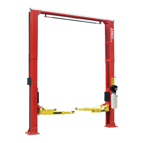
AMGO SL-6 Manual

SINGLE POST LIFT
Model:SL-6
Original

CONTENTS
I. PRODUCT FEATURES AND SPECIFICATIONS...............................................................................................1
II. INSTALLATION REQUIREMENT....................................................................................................................... 3
III. STEPS OF INSTALLATION................................................................................................................................5
IV. EXPLODED VIEW.............................................................................................................................................13
V. TEST RUN............................................................................................................................................................. 21
VI. OPERATION INSTRUCTIONS.......................................................................................................................22
VII. MAINTENANCE SCHEDULE......................................................................................................................... 23
VIII. TROUBLE SHOOTING.................................................................................................................................24
IX. LIFT DISPOSAL ..............................................................................................................................................24

1
I.
PRODUCT FEATURES AND SPECIFICATIONS
CHAIN-DRIVE SINGLE POST MODEL SL-6 FEATURES
· Compact design.
· Hydraulic cylinders, designed and made on ANSI standard, utilizing NOK oil seal in
cylinder.
· Self-lubricating UHMW Polyethylene sliders and bronze bush.
· Manual release safety lock, two-stage lock system
· Super-symmetric arms design with 3-stages front arms and 2-stages rear arms.
· Stackable and screwed type rubber pad.
Fig.1
MODEL SL-6 SPECIFICATIONS
Model
Style
Lifting
Capacity
Lifting
Time
Lifting
Height
Overall
Height
Overall
Width
Minimum Pad
Height
Motor
SL-6
Chain-drived
6,000 lbs
84S/32S
71 7/8”-77 1/8”
108 7/8”
80”
4 1/8”-9 1/4”
1.5HP/
2.0HP

2
Arm Swings View
Fig.2

3
II.
INSTALLATION REQUIREMENT
A. TOOLS REQUIRED
Rotary Hammer Drill(Φ19) Carpenter’s Chalk
Hammer Screw sets
Level Bar Tape Measure(7.5mm)
English Spanner(12″) Pliers
Wrench set:(10#、13#、14#、12#Socket Head Wrench:(4#、5#、6#)
17#、19#、24#、30#)
Fig.3

4
B. Equipment storage and installation requirements.
The equipment should be stored or installed in a shady, normal temperature,
ventilated and dry place.
C. SPECIFICATIONS OF CONCRETE (See Fig. 4)
Specifications of concrete must be adhered to the specification as following.
Failure to do so may result in lift and/or vehicle falling.
1. Concrete must be thickness 6’’ minimum and without reinforcing steel bars and must
be dried completely before the installation.
2. Concrete must be in good condition and must be of test strength 3,000psi minimum.
3. Floors must be level and no cracks.
D. POWER SUPPLY
The electrical source must be 2.0HP minimum. The source cable size must be 2.5mm²
and in good condition of contacting with floor.
95
Fig.4
Concrete Intensity must be 3,000PSI minimum
More than 6’’

5
III.
STEPS OF INSTALLATION
A. Location of installation
Check and insure the installation location (concrete, layout, space size etc.) is suitable
for lift installation.
B. Check the parts before assembly
1. Packaged lift and hydraulic power unit (See Fig. 5)
Column
Power Unit
Base
Carriage
Fig.5

6
2.Take off the packaging on the machine. Take off the packing rack.
3.Move aside the parts and check the parts according to the shipment parts list.
(See Fig.6 & 7)
Fig.6
4. Check the parts of the parts bag according to the parts bag list (See Fig.8)
Part box (65)
Fig.7
Fig.8
65

7
C. Lay the base on the ground, confirm installation place according to the ground
state, the main purpose is to save space. (See Fig.9)
D. Install column and lift platform
1. Lay the column on the ground. (See Fig.10)
2. Connecting oil hose of cylinder (See Fig. 11)
1
Fig. 10
Pull out the carriage
about 200mm
Fig. 11
Fig. 9
Connect oil hose to cylinder connector
66

8
3. Fix column to the base plate. (See Fig.12)
4. Fix lifting platform to carriage. (See Fig.13)
23
30
25
26
27
27
26
50
49
Fig. 12
Fig. 13

9
E. Install safety device, power unit, oil hose and wire holder (See Fig.14)
Note: Tighten the oil hose fitting and power unit fitting to avoid oil leakage; Pay
attention to the direction of power unit fitting.
Fig.14
Tighter the screw with 19#
wrench set after install
power unit fitting.
67
4
9
12
17
14
15
16
18
5
68
13

10
NO NO
A2A2
A1
T1
T2
T3L3
L2
L1
M
~
G
N
L
外
接
电
源
按钮开关
F. Install plastic barrier (See Fig.15)
G. Connect the power source according to the data on plate of power unit
Note: For the safety of operators, the power wiring must contact the floor well
Single phase motor (See Fig. 27)
1. Connecting the two power supply lines (active wire Land neutral wire N) to terminals of AC
contactor marked L1,L2 respectively.
2. Connecting the two motor wires to terminals of AC contactor marked T1, T2.
3. Connecting A2 to L2 of AC contactor.
4. Connecting terminal A1 of AC connector to terminal 4# of push button;
Connecting terminal L1 of AC connector to terminal 3# of push button;
16
18
37
Clip support
36
Fig.15
The plastic barrier
passes through
here
Clip support
Single phase
AC contactor
Fig.16
Push button
Push button
Power supply

11
H. Install lifting arms (see Fig.17); Lowing the carriages down to the lowest position,
then use the 6# wrench to loosen the nut (See Fig. 18) Adjust the arm lock as arrow
direction (See Fig. 19). Adjust moon gear and arm lock to make it to be good engagement,
then tighten the nut of arm lock (See Fig. 20).
Adjust the screw and arm lock
Tighten the screw
Fig.20
Fig.17
Fig.18
Snap Ring
Loosen the screw
Fig.19

12
I. Tighten all the hydraulic fittings, and fill the reservoir with hydraulic oil.
Note: In consideration of Hydraulic Power Unit’s durability and keep the equipment
running in the perfect condition, please use Hydraulic Oil 46#.
J. Using level to measure and adjust the column to be vertical.
K. Fix the anchor bolts
1. Prepare the anchor bolts (See Fig. 22).
2. Using the prescribed rotary hammer drill, and drill all the anchor holes and install the
anchor bolts. Make the columns plumpness, and adjusting with the shims if not, then
tighten the anchor bolts (See Fig. 23).
Note:Torque of Anchors is 150N.m. Minimum embedment of Anchors is 3-1/2”
Use level to measure the
column by front and side
to make sure the column
is vertical
72 Level adjusting shim
Fig.22
Fig.23
73
Fig.21
Drilling
Clearing
Expand
3-1/2’’

13
Ⅳ. Exploded View
Model:SL-6
Fig.24

14
PARTS LIST FOR SL-6
Item
Part#
Description
QTY.
Note
1
11101013
Top Plate assembly
1
2
10206023
Self-Locking Nut M12
4
3
10217069
Hex Bolt
4
4
10209009
Cap Head Bolt
6
5
10209012
(φ3.2)Spring Pin
1
6
11203002
Power Side Safety Device
1
7
10209007
Safety Spring
1
8
11209008
Safety Cover
1
9
11217048
wire clip
2
10
11206002
Safety stop pin
1
11
10206003A
Rubber handle sleeve
1
12
11203013
Coupling
1
13
81513019
Power unit
1
14
10217013
Hex Bolt
1
15
10209149
Washer φ6
1
16
10420045
Washer φ6
9
17
11203015
Power-side Safety Block assembly
1
18
10420018
M6 Self Locking Nut
3
19
10680003
Hex Bolt
2
20
10209034
Washer φ8
4
21
10209033
Washer φ8
4
22
11203035
Stackable Adapter Set
1
23
11101040
Column assembly
1
24
11203034
Support extension sleeve
4
25
10101002
M20*50 Hex Bolt
10
26
10201114
Washer φ20
18
27
10209128
Washer φ20
18
28
11101023
Base assembly
1
29
11101024
ramp assembly
1
30
11102608
carriage assembly
1
31
10217188
Slider Block (46*46*76)
8
32
10207010
cylinder
1
33
10207008
Chain pulley bearing assembly
1
34
10201010A
Chain header
2
35
10101007
Chain
1
36
10101004
Curtain L=2570mm
1
37
10203117
Adjusting screw with hook M6×95
2
38
10201005
Split pin(φ4*50)
1
39
11101025
Drive-in Ramps assembly
1
40
10209020
Plastic ball
4
41
10209021
Hex nut M10
2
42
10209039
Washer φ10
2
43
10209023A
Arm lock
2
44
11201041
Limit Shim
2
45
11101010
Arm Lock Bar
2

15
Item
Part#
Description
QTY.
Note
46
10101034
Outside arm assembly
2
47
10520023
Spring for shaft φ38
2
48
11209030A
Lifting arm latch assembly
2
49
10420175A
M20 Hex nut
8
50
10101001
M20*45 Hex Bolt
8
51
11101016
Lifting platform assembly
1
52
10209025
φ4*25 Elastic pin
4
53
10209026
Compression spring φ1.4
2
54
10203054
Rubber pad assembly
4
55
10101006
Screw M6*12
2
56
11101012
Coupling pin assembly
2
57
10420043
M8*20 Socket screw
8
58
11101005
Lifting arm latch assembly
2
59
10101033
Outer Arm Assembly
2
60
10420043
Socket screw M8*20
4
61
10101008
Arm lock
2
62
11101009
Arm lock fixing plate
2
63
11101011
Control stick assembly
2
64
10720003
Compression spring(φ2*75)
1
65
10102500
Parts box
1
66
10201020
Cylinder 900 3/8NPT(M)*1/4JIC(M) fitting
1
67
10101027
Oil hose assembly (both straight)1/4’’
*1660
1
68
10209060
Power unit 90-degree fitting
1
69
10209003
Hex bolt M8x25
4
70
10209004
Rubber ring(φ8*φ20*3)
4
71
10209005
Self-locking nut M8
4
72
10620065
Leveling pad(2mm)
10
10201090
Leveling pad(1mm)
10
73
10201140
Anchor bolt 3/4*6-1/2
6

16
4.1. Rubber Pad Assembly(10203054)exploded view:
4.2 Outside Arm Assembly(10101033)exploded view:
Item
Part#
Description
QTY
1
10420043
M8*20 Hex Bolt
8
2
10203043
Rubber pad
4
3
11203026
Support pad assy.
4
4
10201060
O-ring(70°)
8
5
11203025
Adjusting screw
4
6
10203041
Retaining ring
4
7
11203024
Adjustment Screw
4
8
10203042
Retaining ring
8
Item
Part#
Description
QTY
1
10209032
Hex bolt M8*25
6
2
10209034
washerφ8
6
3
10209033
washerφ8
6
4
10209035
Moon gear
2
5
11101019
Outside Outer arm assy.
2
6
10201149
M8*12 Screw
2
7
11203101
Inner arm assy.
2
Fig.26
7
2
1
3
4
5
2
4
5
7
8
6
3
1
Fig.25
6

17
4.3 Inside Arm Assembly(10101034)exploded view:
4.4 Cylinder Assy.(10207010)exploded view:
Item
Part#
Description
QTY
1
10209032
M8*25 Hex bolt M8*25
6
2
10209034
washerφ8
6
3
10209033
washerφ8
6
4
10209035
Moon gear
2
5
11203101
Inside Outer arm assy.
2
6
10201149
M8*12 Screw
2
7
11102006
Inside Inner arm assy.
2
Cylinder Explode View
Fig.28
2
1
3
4
5
7
6
Fig.27

18
Item
Part#
Description
QTY
Item
Part#
Description
QTY
1
11207027
Piston Rod
1
8
11207029
Adjustment Tube
Cylinder
1
2
11207028
Piston
1
9
10217078
Dust Ring
1
3
10206069
O-Ring
1
10
10520058
O-Ring
1
4
10620053
Support Ring
1
11
11207030
Head Cap
1
5
10620054
Y-Ring
1
12
10201034
silencer
1
6
10630027
O-ring
1
13
10207031
O-Ring
1
7
10206071
Hex Nut
1
14
11207032
Cylinder Tube
1
4.5 Chain Pulley Support Assy.(11207681)exploded view:
Item
Part#
Description
QTY
1
81400335
Hex bolt M5*10
2
2
11207006
Chain Pulley Pin
1
3
10420132A
Chain Pulley bush φ41.2*φ35.2*20
2
4
11207693
Chain retainer
1
5
11207007
Chain Pulley
1
6
10201005
Split pin(φ4*50)
1
7
11207008
Chain Pulley Bracket
1
Fig.29
Table of contents
Other AMGO Lifting System manuals
Popular Lifting System manuals by other brands

Space
Space SB 1396 E manual

Textron
Textron Greenlee 4024 Assembly instructions, illustrations & parts list

MORISPAIN
MORISPAIN MH KOMPACT user manual

Braun
Braun RA400 Operator's installation and instruction manual

SYSTEMS
SYSTEMS McGuire VSH Series Owner & user manual

Sinoboom
Sinoboom GTJZ0608E Maintenance manual