Thiele TWN 0121/1 User manual
OPERATING INSTRUCTIONS
LIFTING POINTS, SCREW TYPE
THIELE GmbH & Co. KG # Change indicator
www.thiele.de | info@thiele.de B07905-M replaces B07905-L
© All rights reserved EN 07.2021 1 | 6
Original in compliance with 2006/42/EC
TWN 0121/1
TWN 0122
TWN 0123
TWN 0127
TWN 1120
TWN 1830
TWN 1884
TWN 1890
1DESCRIPTIONAND INTENDED USE
THIELE lifting points screw-type are intended for attachment to steel, aluminum or
non-ferrous metal structures and components.
Sling chains according to EN 818-4 or lashing chains according to EN 12195 may be
used.
These Operating Instructions show the safety use of THIELE lifting points of the
following executions:
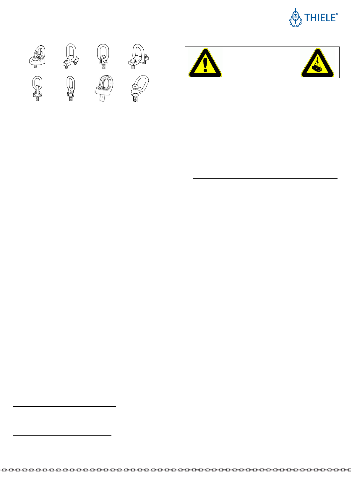
•TWN 0121/1 Lifting points, rotabable, with slide bearing
•TWN 0122 Lifting points
•TWN 0123 Lifting points
•TWN 0127 Lifting points MDB
•TWN 1120 TITAN Lifting points, rotabable, with slide bearing
•TWN 1830 X-TREME Lifting points, rotabable, with ball bearing
•TWN 1884 KE-Eyebolt, rotabable, with ball bearing
•TWN 1890 Lifting points XS-Point, rotabable
(TWN = THIELE workshop standard)
THIELE lifting points meet EG Machinery Directive 2006/42/EG requirements and
feature a safety factor of at least 4 based on the Working Load Limit (WLL).
THIELE lifting points are signed with the CE symbol.
They are also signed with the Working Load Limit (WLL) in tons or the chain size,
manufacturers mark (stamp ’H4’) and identification number.
TWN 1830 are additionally marked with the date of manufacture in the form "mm.yy"
(mm = month, yy = year). Example: "1220" = production in December 2020
THIELE lifting points are designed to withstand 20 000 dynamic load changes under
maximum load conditions. In the event of higher loads (e.g. multi-shift/automatic
operation, magnetic spreaders) the Working Load Limit must be reduced.
Lifting points must exclusively be used
•within the limits of their permissible working load limit,
•within the temperature limits prescribed,
•with suitable screws (see screw data) and fitted directly to the component.
The Working Load Limit of different modes of assembly can be seen in the load table.
THIELE lifting points are normally not intended for passenger transportation.
Turning and rotating loads
•TWN 0121/1 Turning allowed, rotating not allowed.
•TWN 0122 Turning allowed, rotating not allowed.
•TWN 0123 No turning and/or rotating allowed.
•TWN 0127 Turning allowed, rotating not allowed.
•TWN 1120 Turning allowed, rotating not allowed.
•TWN 1830 Turning and rotating allowed.
•TWN 1884 Turning allowed, rotating not allowed.
•TWN 1890 Turning allowed, rotating not allowed.
This classification relates to occasionally turning or rotating loads.
Continous or long-term turning or rotating is not allowed.
Using the lifting points exclusively for lashing the Lashing Capacity is calculated by
doubling the Working Load Limit.
An alternating use for lifting and lashing is not allowed.
2SAFETY NOTES
Risk of Injury!
Never walk or stay under lifted loads!
Make sure to use hoisting/ attach me n t
means free from defects.
•Operators, fitters, and maintenance personnel must in particular observe the
Operating Instructions also from the used sling chain assemblies, documentations
DGUV V 1, DGUV R 100-500 Chapter 2.8 and DGUV I 209-013 issued by the German
Employers’ Liability Insurance Association, as well as the Operating Instructions of
the loads concerning advise for lifting.
•In the Federal Republic of Germany, the Operational Safety Ordinance (BetrSichV)
has to be implemented and the Technical Rule for Industrial Safety TRBS 1201, in
particular Annex 1, Chapter 2 "Special regulations for the use of working
equipment for lifting loads" must be observed.
•Outside the Federal Republic of Germany the specific provisions issued locally in
the country where the items are used must also be observed.
•The directions given in these Operating Instructions and specified documentations
relating to safety, assembly, operation, inspection, and maintenance must be
made available to the respective persons.
•Make sure these Operating Instructions are available in a place near the product
during the time the equipment is used.
•Please contact the manufacturer if replacements are needed.
•When performing work make sure to wear your personal protective equipment!
•Improper assembly and use may cause personal injury and/or damage to
property.
•Assembly and removal as well as inspection and maintenance must exclusively be
carried out by skilled and authorized persons.
•Structural changes are impermissible (e.g. welding, bending).
•Operators must carry out a visual inspection and, if necessary, a functional test
of the safety equipment before each use.
•Never use worn-out, bent or damaged lifting points.
•Only lift loads the mass of which is less than or equal to the working load limit of
the lifting points.
•Do not use force when mounting/positioning the lifting points.
•Only lift loads that are freely movable and not attached or fastened.
•Do not bend the ring or suspension link.
•Do not start lifting before you have made sure the load has been correctly
attached.
•Make sure no one including you (operator) is in the way of the moving load (hazard
area).
•During lifting/hoisting make sure your hands or other body parts do not come into
contact with hoisting means. Only remove hoisting means manually (use your
hands).
•Avoid impacts, e.g. due to abruptly lifting loads with chain in slack condition.
•Never move a suspended load over persons.
•Never cause suspended loads to swing.
•Always monitor a suspended load.
•Put the load only down in places/sites where it can be safely deposited.
•Put the load only down in flat places/sites where it can be safely deposited.
•Take care for sufficient place for the personnel to move when choosing the route
of transportation and storage location. Danger to life and risk of injury by crushing
hazards!
•In the event of doubts about the use, inspection, maintenance or similar things
contact your safety officer or the manufacturer!
THIELE will not be responsible for damage caused through non-observance of the
instructions, rules, standards and notes indicated!
Working under the influence of drugs, medications impairing the sense and/or
alcohol is strictly forbidden!
OPERATING INSTRUCTIONS
LIFTING POINTS, SCREW TYPE
THIELE GmbH & Co. KG # Change indicator
www.thiele.de | info@thiele.de B07905-M replaces B07905-L
© All rights reserved EN 07.2021 2 | 6
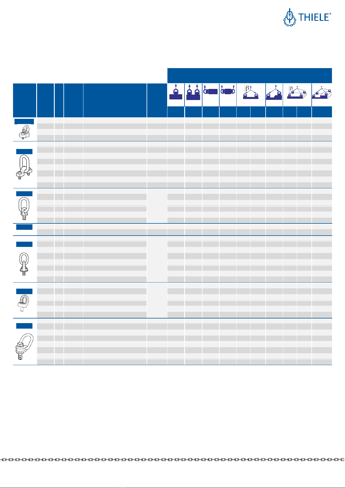
3TECHNICAL DATA
3.1 All types without TWN 1830
Load Table [t]
TWN
Article
No.
WLL
[t]
Usable
thread
length
[mm]
Screw data / Suspension link
[dimensions in mm]
Tightenin g
torque
[Nm]
1-leg
2-leg
1-leg
2-leg
2-leg
2-leg
3-/4-leg
3-/4--leg
0°
0°
90°
90°
0°- 45°
45°- 60°
dissym.
3)
0°- 45°
45°- 60°
dissym.
3)
TWN 0121/1
F35000
1,12
M16 x 25
M16 x 40 DIN 7984 8.8
170
1)
1,12
2,24
1,12
2,24
1,6
1,12
1,12
2,4
1,7
1,12
F35010
2,0
M20 x 30
M20 x 50 DIN 7984 8.8
350
1)
2,0
4,0
2,0
4,0
2,8
2,0
2,0
4,2
3,0
2,0
F35020
3,15
M24 x 36
M24 x 60 DIN 7984 8.8
600
1)
3,15
6,3
3,15
6,3
4,5
3,15
3,15
6,7
4,7
3,15
F35030
5,3
M30 x 50
M30 x 80 DIN 6912 10.9
1 200
1)
5,3
10,6
5,3
10,6
7,5
5,3
5,3
11,2
8,0
5,3
TWN 0122
F35070
3,15
M16 x 25
M16 x 45 DIN 7984 10.9
2)
170
1)
3,15
6,3
3,15
6,3
4,5
3,15
3,15
6,7
4,7
3,15
F35075
5,3
M20 x 36
M20 x 60 DIN 7984 10.9
2)
350
1)
5,3
10,6
5,3
10,6
7,5
5,3
5,3
11,2
8,0
5,3
F35080
8,0
M30 x 50
M30 x 80 DIN 6912 10.9
2)
950
1)
8,0
16
8,0
16
11,3
8,0
8,0
17
12
8,0
F35095
15
M36 x 53
M36 x 90 DIN 6912 10.9
2)
1 900
1)
15
30
15
30
21,2
15
15
31,8
22,5
15
F35098
21,2
M42 x 67
M42 x 100 sim.DIN7984 10.9 Sp.
2)
2 100
1)
21,2
42,4
21,2
42,4
30
21,2
21,2
45
31,8
21,2
F35101
25
M45 x 67
M45 x 110 sim.DIN7984 10.9 Sp.
2)
2 400
1)
25
50
25
50
35,4
25
25
53
37,5
25
F35102
31,5
M56 x 88
M56 x 135 sim.DIN7984 10.9 Sp.
2)
3 200
1)
31,5
63
31,5
63
44,5
31,5
31,5
66,8
47,3
31,5
F35285
36
M56 x 88
M56 x 135 sim.DIN7984 10.9 Sp.
2)
3 200
1)
36
72
36
72
50,9
36
36
76,4
54
36
TWN 0123
F34110
1,12
M16 x 30
B16 x 70 x 35
hand-
screwed
1,12
2,24
1,12
2,24
1,6
1,12
1,12
2,4
1,7
1,12
F34115
1,12
M16 x 30
A16 x 110 x 60
1,12
2,24
1,12
2,24
1,6
1,12
1,12
2,4
1,7
1,12
F34120
2,0
M20 x 38
B16 x 70 x 35
2,0
4,0
2,0
4,0
2,8
2,0
2,0
4,2
3,0
2,0
F34121
2,0
M20 x 38
A16 x 110 x 60
2,0
4,0
2,0
4,0
2,8
2,0
2,0
4,2
3,0
2,0
F34130
3,15
M24 x 35
B18 x 85 x 40
3,15
6,3
3,15
6,3
4,5
3,15
3,15
6,7
4,7
3,15
F34131
3,15
M24 x 45
A18 x 110 x 60
3,15
6,3
3,15
6,3
4,5
3,15
3,15
6,7
4,7
3,15
TWN 0127
F35157
3,15
M20 x 38
M20 x 50 ISO 4017 10.9
2)
350
3,15
6,3
3,15
6,3
4,5
3,15
3,15
6,7
4,7
3,15
F35158
5,3
M24 x 35
M24 x 50 ISO 4017 10.9
2)
600
5,3
10,6
5,3
10,6
7,5
5,3
5,3
11,2
8,0
5,3
TWN 1120
F34405
0,3
M8 x 18
M8 x 35 12.9
hand-
screwed by
open-ended
spanner
0,3
0,6
0,3
0,6
0,42
0,3
0,3
0,64
0,45
0,3
F34390
0,45
M10 x 18
M10 x 35 12.9
0,45
0,9
0,45
0,9
0,64
0,45
0,45
0,95
0,68
0,45
F34395
0,6
M12 x 23
M12 x 40 12.9
0,6
1,2
0,6
1,2
0,85
0,6
0,6
1,3
0,9
0,6
F34400
1,4
M16 x 28
M16 x 45 10.9
2,1
4,2
1,4
2,8
2,0
1,4
1,4
3,0
2,1
1,4
F34410
2,5
M20 x 32
M20 x 50 10.9
3,0
6,0
2,5
5,0
3,5
2,5
2,5
5,3
3,8
2,5
F34420
3,5
M24 x 40
M24 x 60 10.9
6,0
12
3,5
7,0
4,9
3,5
3,5
7,4
5,3
3,5
F34430
6,7
M30 x 52
M30 x 80 12.9
7,1
14,2
6,7
13,4
9,5
6,7
6,7
14,2
10
6,7
F34440
8,0
M36 x 66
M36 x 100 12.9
12,5
25
8,0
16
11,3
8,0
8,0
17
12
8,0
TWN 1884
F38005
0,5
M8 x 16
DIN 7991 M8 x 30 10.9
hand-
screwed by
allen key
0,5
1,0
0,5
1,0
0,7
0,5
0,5
1,0
0,75
0,5
F38006
0,75
M10 x 16
DIN 7991 M10 x 30 10.9
0,75
1,5
0,75
1,5
1,0
0,75
0,75
1,5
1,1
0,75
F38007
1,0
M12 x 18
DIN 7991 M12 x 35 10.9
1,0
2,0
1,0
2,0
1,4
1,0
1,0
2,1
1,5
1,0
F38010
1,7
M16 x 27
DIN 7991 M16 x 50 10.9
1,7
3,4
1,7
3,4
2,4
1,7
1,7
3,6
2,5
1,7
F38020
2,6
M20 x 33
DIN 7991 M20 x 60 10.9
2,6
5,2
2,6
5,2
3,6
2,6
2,6
5,5
3,9
2,6
F38030
3,2
M24 x 39
DIN 7991 M24 x 70 10.9
3,5
7,0
3,5
7,0
4,9
3,5
3,5
7,0
5,2
3,5
TWN 1890
F35243
0,63
M10 x 17
M10 x 45 ISO 4017 12.9
80
0,63
1,26
0,63
1,26
0,89
0,63
0,63
1,3
0,95
0,63
F35244
1,0
M12 x 22
M12 x 50 ISO 4017 12.9
130
1,0
2,0
1,0
2,0
1,4
1,0
1,0
2,1
1,5
1,0
F35245
1,7
M16 x 30
M16 x 70 ISO 4017 10.9
180
1,7
3,4
1,7
3,4
2,4
1,7
1,7
3,6
2,6
1,7
F35246
2,5
M20 x 38
M20 x 80 ISO 4017 10.9
350
2,5
5,0
2,5
5,0
3,5
2,5
2,5
5,3
3,8
2,5
F35247
4,0
M24 x 40
M24 x 90 ISO 4017 12.9
500
4,0
8,0
4,0
8,0
5,7
4,0
4,0
8,5
6,0
4,0
F35249
6,0
M30 x 44
M30 x 100 ISO 4017 10.9
500
6,0
12
6,0
12
8,5
6,0
6,0
12,7
9,0
6,0
F35250
8,0
M36 x 64
M36 x 120 ISO 4017 12.9
750
8,0
16
8,0
16
11,3
8,0
8,0
17
12
8,0
F35251
10
M42 x 74
M42 x 140 ISO 4017 10.9
950
10
20
10
20
14,1
10
10
21,2
15
10
1) For tapped holes in steel
2) Additional technical THIELE-specification must be observed
3) Reduced WLL according to DIN 685-5
OPERATING INSTRUCTIONS
LIFTING POINTS, SCREW TYPE
THIELE GmbH & Co. KG # Change indicator
www.thiele.de | info@thiele.de B07905-M replaces B07905-L
© All rights reserved EN 07.2021 3 | 6
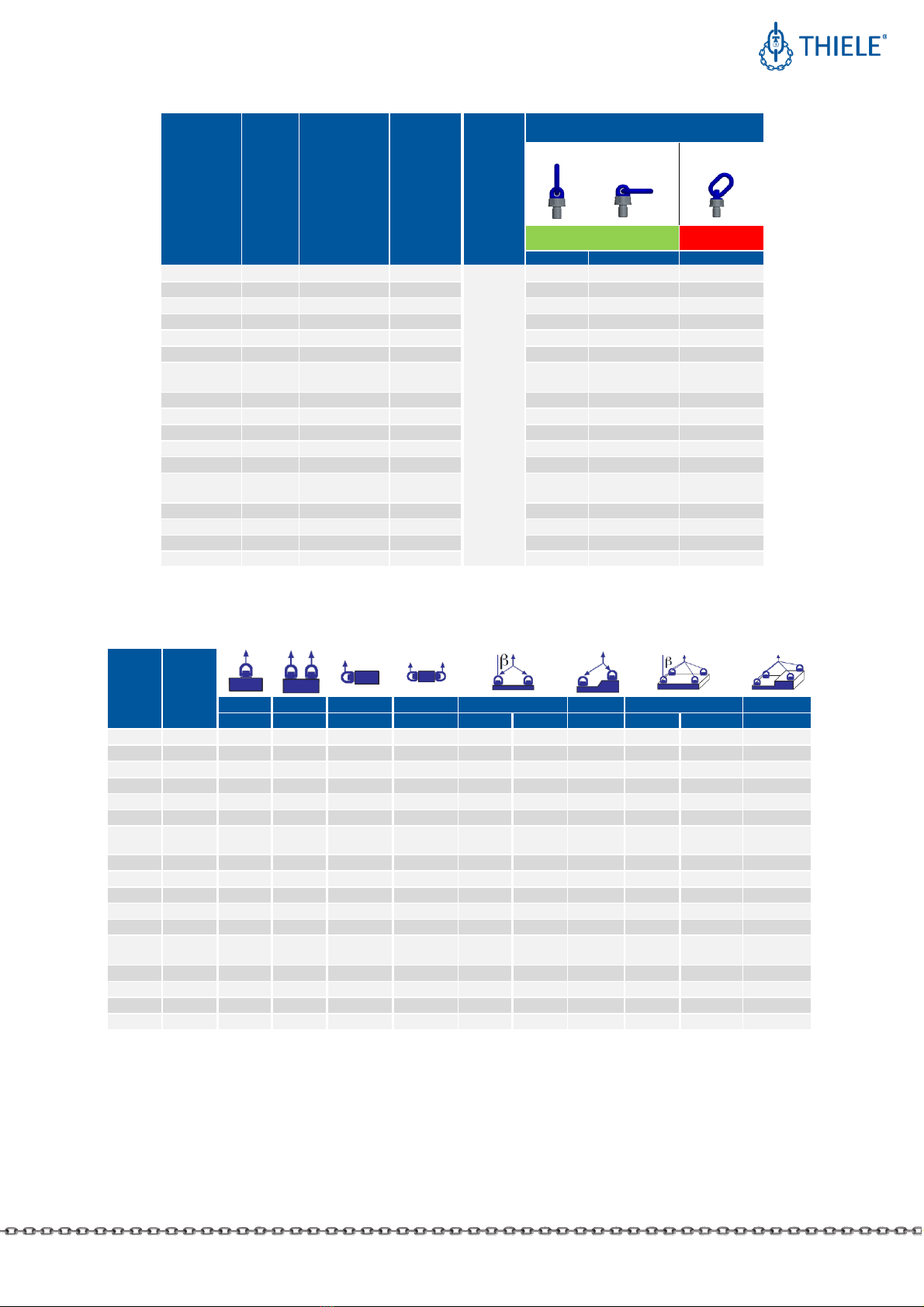
3.2 Technical data for TWN 1830
Nominal WLL
[t]
Article-
No.
Suspension link
[mm]
Thread
d x G
[mm]
Tightenin g
torque
[Nm]
Working Load Limit for each lifting point
depending on alignment and inclination angle
= ± 5°
5° < ≤105°
5° < ≤45°
P R E F E R E D
to avoid
[t]
[t]
[t]
0,45
F34306
B13 x 55 x 33
M10 x 15
hand-
screwed
0,9
0,6
0,45
0,6
F34307
B13 x 55 x 33
M12 x 18
1,2
0,75
0,6
1,4
F34300
B13 x 55 x 33
M16 x 20
2,8
1,7
1,4
2,5
F34310
B16 x 70 x 35
M20 x 25
5,3
2,8
2,5
3,5
F34320
B18 x 85 x 40
M24 x 30
7,0
4,0
3,5
5,3
F34330
B22 x 100 x 50
M30 x 40
10
6,3
5,3
8,0
F34340
B22 x 100 x 50
M36 x 50
15
9,5 1)
10 2)
8,0
10
F34350
B32 x 140 x 70
M42 x 60
18
13
10
12,5
F34353
B32 x 140 x 70
M45 x 65
20
15
12,5
12,5
F34355
B32 x 140 x 70
M48 x 68
20
16
12,5
12,5
F34361#
B32 x 140 x 70
M52 x 78 #
20
16
12,5
17
F34360
B32 x 140 x 70
M56 x 78
28
22
17
17
F34363
B32 x 140 x 70
M64 x 96
28
22 1)
25 2)
17
31,5
F34380
B45 x 220 x 110
M72 x 108
50
40
31,5
35
F34383
B45 x 220 x 110
M80 x 120
50
48
35
40 t
F34385
B45 x 220 x 110
M90 x 135
50
50
40
40 t
F34388
B45 x 220 x 110
M100 x 150
50
50
40
1) until date of manufacture „1220“ (December 2020)
2) from date of manufacture „0121“ (January 2021)
Working Load Limit (WLL) depending on number of legs and inclination angle in t
Nominal
WLL
[t]
Thread
[mm]
1-leg
2- leg
1- leg
2- leg
2- leg 5)
2- leg 5)
3-/4- leg5)
3-/4- leg5)
± 5°
± 5°
75- 105°
75- 105°
0°- 45°
45°- 60°
dissym.6)
0°- 45°
45°- 60°
dissym.6)
0,45
M10
0,9
1,8
0,6
1,2
0,85
0,6
0,6
1,3
0,9
0,6
0,6
M12
1,2
2,4
0,75
1,5
1,0
0,75
0,75
1,57
1,12
0,75
1,4
M16
2,8
5,6
1,7
3,4
2,4
1,7
1,7
3,6
2,6
1,7
2,5
M20
5,3
10,6
2,8
5,6
4,0
2,8
2,8
5,9
4,2
2,8
3,5
M24
7,0
14
4,0
8,0
5,7
4,0
4,0
8,5
6,0
4,0
5,3
M30
10
20
6,3
12,6
8,9
6,3
6,3
13,4
9,5
6,3
8,0
M36
15
30
9,5 3)
104)
193)
204)
13,4 3)
14,1 4)
9,5 3)
104)
9,5 3)
104)
20,2 3)
21,2 4)
14,3 3)
154)
9,5 3)
104)
10
M42
18
36
13
26
18,2
13
13
27,3
19,5
13
12,5
M45
20
40
15
30
21,2
15
15
31,8
22,5
15
12,5
M48
20
40
16
32
22,6
16
16
33,9
24
16
12,5
M52 #
20
40
16
32
22,6
16
16
33,9
24
16
17
M56
28
56
22
44
31,1
22
22
46,7
33
22
17
M64
28
56
223)
254)
443)
504)
31,1 3)
35,3 4)
223)
254)
223)
254)
46,7 3)
534)
333)
37,5 4)
223)
254)
31,5
M72
50
100
40
80
56
40
40
85
60
40
35
M80
50
100
48
96
68
48
48
102
72
48
40
M90
50
100
50
100
71
50
50
106
75
50
40
M100
50
100
50
100
71
50
50
106
75
50
3) until date of manufacture „1220“ (December 2020)
4) from date of manufacture „0121“ (January 2021)
5) for the prefered alignment
6) Reduced WLL according to DIN 685-5

OPERATING INSTRUCTIONS
LIFTING POINTS, SCREW TYPE
THIELE GmbH & Co. KG # Change indicator
www.thiele.de | info@thiele.de B07905-M replaces B07905-L
© All rights reserved EN 07.2021 4 | 6
4COMMISSIONING
Prior to using the components for the first time make sure that
•the lifting points comply with the order and have not been damaged,
•test certificate, statement of compliance, and operating instructions are at hand,
•markings correspond with what is specified in the documentation,
•inspection deadlines and the qualified persons for examinations are determined,
•visibility and functional testing are carried out and documented,
•documentations are safely kept in an orderly manner.
Dispose of the packing in an environmentally compatible way according to local rules.
5ASSEMBLY AND REMOVAL
5.1 Preparations
The mounting location for each lifting point must ensure that
•the load can take the forces safely to be applied without suffering deformation,
•the lifting point can be assembled flush,
•no areas of danger are created (crushing point, shearing point),
•transportation is not restrained by overhang,
•deflections of sling parts are avoided,
•incorrect use is avoided,
•the suspension gear cannot be damaged, for example by sharp edges,
•the lifting point can be used easily.
5.2 Assembly
The useful depth of the thread must enable the lifting points to be safely screwed in.
Use only the delivered screws!
Make sure the tapped hole is arranged at right angle to the attachment face on the
component. The depth of the thread „L“ of the component must at least be as follows:
L = 1,0 x d for steel
L = 1,25 x d for castings
L = 2,0 x d for aluminum
L = 2,5 x d in aluminum-magnesium-alloys
(L = depth of thread; d = thread diameter)
•Make sure the threads of the lifting point and in the
component are clean and dry.
•If lifting points should remain on the component a thread
locker has to be used.
•In case of a bolted joint the nut must be secured against unintentionally loosening.
•TWN 0123, TWN 1120, TWN 1830 and TWN 1884:
Use a suitable open-ended spanner, ring spanner or allen key to fix the lifting
points hand-tight.
•TWN 0121/1, TWN 0122, TWN 0127 and TWN 1890:
Take care to tighten the screws by the right torque shown in the table. As long as
it is ensured there is no load turning for a singular use and the lifting point cannot
be loosened a hand tightening of the lifting points by a suitable open-ended
spanner or ring spanner is sufficient. An additional check is necessary in case of a
repeated load lowering.
•TWN 1830 and TWN 1884:
Take care not to exceed the tightening torque of 40 Nm for screws M10 and M12.
There must be made a chamfer on the hole for the thread:
Thread [mm]
Chamfer [mm]
M8
1,5
+0,5
x 45°
M10, M12
2,0
+0,5
x 45°
M16, M20
2,5
+0,5
x 45°
M24, M30
3,5
+0,5
x 45°
M36 - M48
4,0
+0,5
x 45°
M52
#
- M100
4,5
+0,5
x 45°
6CONDITIONSOFUSE
6.1 Normal Use
The top part of the lifting point including attachment link must always be freely
movable.
It must not rest on or be supported by other structural parts.
When attaching the components make sure the position of the lifting point always
enables forces to be exerted in longitudinal direction of the suspension link.
Make sure only the top parts of the lifting points turn into loading direction and not
the firmly secured stationary portion.
Using 4-leg chain link assemblies may cause higher risk because only 2 opposite legs
carrying the load. Check the Working Load Limit of lifting point and chain link assembly
carefully and chose if necessary bigger sizes.
The force must be applied lengthwise to the suspension link.
TWN 1830:
The lifting point must not be used for a permanent or prolonged turning of the load.
to prefer to avoid not permitted
TWN 1890:
TWN 1884:
Components connected to the eyelet must always be able to move freely.
6.2 Use in through holes #
If screwable lifting points are fastened by means of nuts in holes (e.g. of metal sheets),
the following conditions must be observed:
•Rotating or turning the load is not permitted.
•The strength class of the nuts must be 10 or higher.
•The chamfer at the end of the screw thread must protrude from the nut.
•It must be ensured that the component to be lifted is suitable to withstand the force
to be applied safely and without deformation, including the corresponding safety
factors.
•Suitable action must be taken to ensure that the nut cannot loosen unintentionally,
e.g. suitable torque or threadlocker.
OPERATING INSTRUCTIONS
LIFTING POINTS, SCREW TYPE
THIELE GmbH & Co. KG # Change indicator
www.thiele.de | info@thiele.de B07905-M replaces B07905-L
© All rights reserved EN 07.2021 5 | 6
6.3 Influence of Temperature
The permissible Working Load Limit of the lifting points reduces at elevated
temperatures.
The reduced Working Load Limit figures shown in the following tables shall only apply
for short-term use at the temperatures indicated.
Temperatu re range
1) #
Remaining Workin g Load Limit (WLL)
-20 °C ≤ t ≤ 100 °C
100 %
100 °C < t ≤ 200 °C
85 %
200 °C < t ≤ 250 °C
80 %
250 °C < t ≤ 300 °C
75 %
1)
other temperatu re ranges only after consultatio n with the manufac tu re r
If the lifting points have been exposed to temperatures exceeding the maximum values
specified, they must no longer be used.
TWN 1830 and TWN 1884:
Take care for a loss of lubricant depending on several fitting positions and higher
temperatures. A higher wear may occur.
Shorten the inspection interval for that case.
6.4 Environmental Influence
Lifting points must not be used in environments where acids, aggressive or corrosive
chemicals or their fumes are present.
Hot-dip galvanizing or a galvanic treatment is prohibited as well.
7INSPECTIONS, MAINTENANCE AND DISPOSAL
7.1 General
Inspections and maintenance must be arranged for by the owner!
Inspection deadlines shall be determined by the owner!
Inspections must be carried out and documented by competent persons regularly but
at least once a year, or more frequently if the lifting points are in heavy-duty service.
After three years at the latest they must additionally be examined for cracks. A load
test shall never be considered a substitute for this examination.
The results of the inspection shall be entered into a register (DGUV I 209-062 or DGUV
I 209-063) to be prepared when the lifting point is firstly used. The register will show
characteristic data of the lifting points and other components as well as identity details.
Immediately stop using lifting points that show the following defects:
•missing or illegible identification/marking,
•deformation, elongation or fractures,
•cuts, notches, cracks, incipient cracks, pinching,
•no freely rotating or turning possible,
•heating beyond permissible limits,
•severe corrosion,
•wear exceeding 10 %, for example in the suspension link diameter area,
•defect screws,
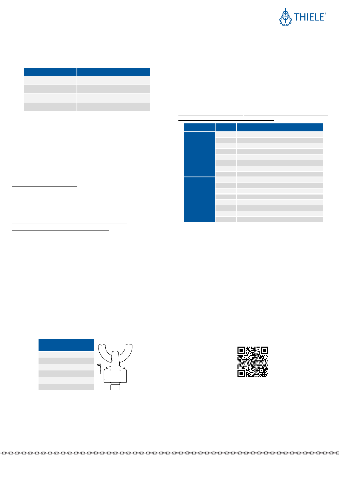
•TWN 1830: gap size „s“ exceeds figures in table below:
Max. gap size „s“ for TWN 1830
Thread
s [mm]
M10 –M20
1.5
M24
2.0
M30
2.5
M36
3.0
M42 –M64
3.5
M72 –M100
4,0
Inspection Service
THIELE offers inspection, maintenance and repair services for lifting points performed
by trained and competent personnel.
7.2 Maintenance
Maintenance and repair work must only be performed by competent persons.
Minor notches and cracks at suspension links may be eliminated by careful grinding
observing the maximum cross section reduction requirement of 10 % and avoid making
more severe cuts or scores.
All maintenance and repair activities are to be documented.
7.3 Disposal
All components and accessories of steel taken out of service are to be scrapped in line
with local regulations and provisions.
8SPARE PARTS
Only use original THIELE-spare parts. Exclusively use original THIELE screws and bolts
because these are made to meet special requirements.
Type
WLL
Article No.
Screw data
TWN 0127
3,15
Z07742
M20 x 50 ISO 4017 10.9
5,3
Z09017
M24 x 50 ISO 4017 10.9
TWN 1884
0,5
Z11727
DIN 7991 M8 x 30 10.9
0,75
Z11728
DIN 7991 M10 x 30 10.9
1,0
Z11363
DIN 7991 M12 x 35 12.9
1,7
Z10869
DIN 7991 M16 x 50 10.9
2,6
Z11200
DIN 7991 M20 x 60 10.9
3,5
Z11199
DIN 7991 M24 x 70 10.9
TWN 1890
0,63
Z10836
M10 x 45 ISO 4017 12.9
1,0
Z10795
M12 x 50 ISO 4017 12.9
1,7
Z09544
M16 x 70 ISO 4017 10.9
2,5
Z08692
M20 x 80 ISO 4017 10.9
4,0
Z09809
M24 x 90 ISO 4017 12.9
6,0
Z07810
M30 x 100 ISO 4017 12.9
8,0
Z07828
M36 x 120 ISO 4017 12.9
10
Z10136
M42 x 140 ISO 4017 10.9
9USE OF DIFFERENT SCREWS
If local circumstances dictate that different screws must be used from those supplied
with the installation, or listed in Section 8, the operator must ensure that
•these fasteners conform to the specified diameter and strength class ,
•they can achieve the minimum required screw-in depth,
•they are 100 % crack tested,
•each bolt has a proven notched impact energy of min. 36 J as a mean value of
three samples tested at -20 °C or at the lowest fitting temperature, if this is below
-20 °C, and that none of the samples fall below 25 J,
•written confirmation of the crack test and impact energy results is enclosed with
the technical documentation.
10 STORAGE
Lifting points have to be stored in dry locations at temperatures ranging between 0 °C
and +40 °C.
11 THIELE OPERATING AND MOUNTING INSTRUCTIONS
Current operating and installation instructions are available as a PDF download on the
homepage.
12 PUBLISHING INFORMATION
THIELE GmbH & Co. KG, Werkstraße 3, 58640 Iserlohn, Germany
Tel.: +49(0)2371/947-0
Email: info@thiele.de

OPERATING INSTRUCTIONS
LIFTING POINTS, SCREW TYPE
THIELE GmbH & Co. KG # Change indicator
www.thiele.de | info@thiele.de B07905-M replaces B07905-L
© All rights reserved EN 07.2021 6 | 6
EU DECLARATION OF CONFORMITY
acc. to Machinery Directive 2006/42/EG, Annex II A for a machine
THIELE GmbH & Co. KG herewith declares as manufacturer that
•TWN 0121/1 Lifting points, rotatable, with slide bearing
•TWN 0122 Lifting points
•TWN 0123 Lifting points
•TWN 0127 Lifting points MDB
•TWN 1120 TITAN Lifting points, rotatable, with slide bearing
•TWN 1830 X-TREME Lifting points, rotatable, with ball bearing
•TWN 1884 KE-Eyebolts
•TWN 1890 Lifting points XS-Point, rotatable
are placed on the market in the form of a complete machine by THIELE together with
the relevant test certificate and are in compliance with the applicable provisions of the
EU Machinery Directive 2006/42/EG.
The following harmonized standards have been observed:
•DIN EN ISO 12100
•DIN EN 1677-1
•DIN EN 1677-4
Other standards and specifications have also been observed as follows:
•DIN 685-5
•DIN 5688-3
This declaration/statement is not meant to warrant any product properties.
Safety notes and instructions pertinent to the products must be observed.
Responsible for the documentation: Iserlohn, 27th July 2021
Rene Völz Dr. Michael Hartmann
(Head of QA and EP) (Managing Director)
Tel.: +49(0)2371/947-541
Other manuals for TWN 0121/1
3
This manual suits for next models
7
Table of contents
Other Thiele Lifting System manuals


Popular Lifting System manuals by other brands


Meganex
Meganex MEG16 instruction manual

JLG
JLG DVL Series Operation and safety manual

ATH-Heinl
ATH-Heinl Flex Lift 30 operating instructions

Safelift
Safelift PushAround PA35 Original instructions

Telpro
Telpro PARAGON PRO TROLL 112 manual

Snorkel
Snorkel MHP 13/35 Mark II Maintenance and repair parts manual