THIEMAN TVLR 125 User manual

TVLR SERIES
Railgates By THIEMAN
TVLR 125, 16, 20, 30
INSTALLATION INSTRUCTIONS
IMPORTANT! KEEP IN VEHICLE!
!
PLEASE EAD AND UNDE STAND THE CONTENTS OF THIS
MANUAL BEFO E OPE ATING THE EQUIPMENT.
TAILGATES, INC.
600 East Wayne Street
Celina, Ohio 45822
Phone: 419-586-7727 Fax: 419-586-9724
HIEMAN
NTEA
THE ASSOCIATION FOR THE WORK TRUCK INDUSTRY
TM
MEMBER

2.
ATTENTION INSTALLE S:
Changes are made periodically to the installation procedure to comply with engineering
changes. To ensure proper liftgate operation, it is VE Y IMPO TANT to read and understand
the installation instructions before attempting an installation. Installers also MUST read and
understand the liftgate’s Owner’s Manual before installing the liftgate, so they can operate the
liftgate safely as required during different stages of the installation process. NEVE perform a
modification on the liftgate, which is not specifically covered in this manual or which is
unauthorized by Thieman. Modifications may result in failure of the liftgate and may create
hazards for liftgate installers, operators, or maintainers. Serious damage, equipment failure, or
operator injury could result from improper installation. This equipment MUST have all decals
applied properly. FAILU E to apply all decals properly will VOID all warranties! Any installer
with questions or doubts should contact Thieman before proceeding.
NOTES:
1. All maximum mounting dimensions are shown with the vehicle empty; all minimum mounting
dimensions are shown with the vehicle loaded.
2. Check the bed height when vehicle is parked on a level surface.
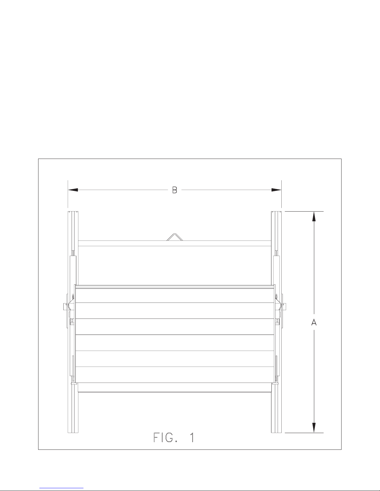
3. Refer to figure 1 and table 1 for overall dimensions of liftgates and bed height ranges for
different models.
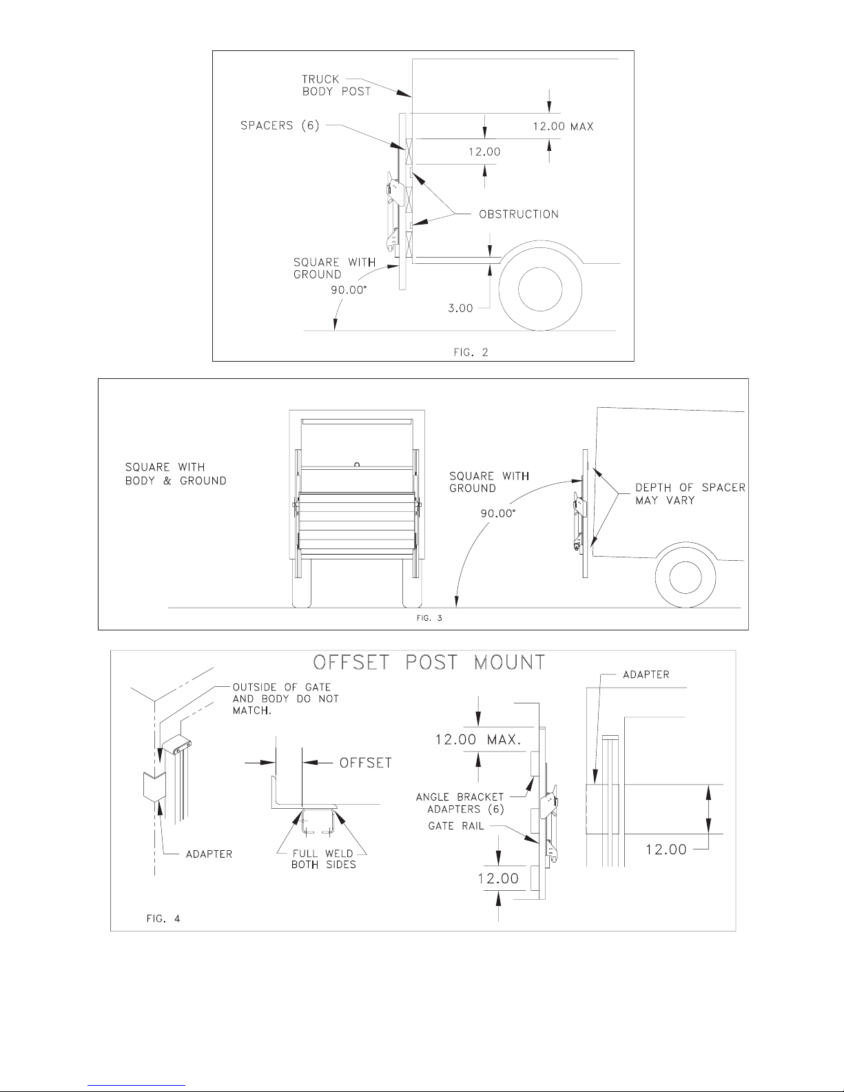
4. The TVLR series railgates are all level ride, which means when the vehicle is located on a
level surface, the rails should be perpendicular to the ground. When mounting, consideration
should be given to the platform position with the truck both empty and loaded. See figure 2
and 3.
NOTES:
1. All bed height ranges shown in table 1 allow installer to provide a minimum of 18" of ground
clearance by cutting off the lower end of the rail as needed unless otherwise stated. Rails
must NOT be cut more than 25" above the ground (Note: 25” measurement must be made
with truck unloaded. See Step 12 of Installation Instructions. On special orders, consult
factory as the allowable trim dimensions may vary from what is shown here).
2. Optional light covers in which the lights are below the cylinder housing will not allow the total
18" inches of ground clearance on standard bed models in the bed height range of 33-36".
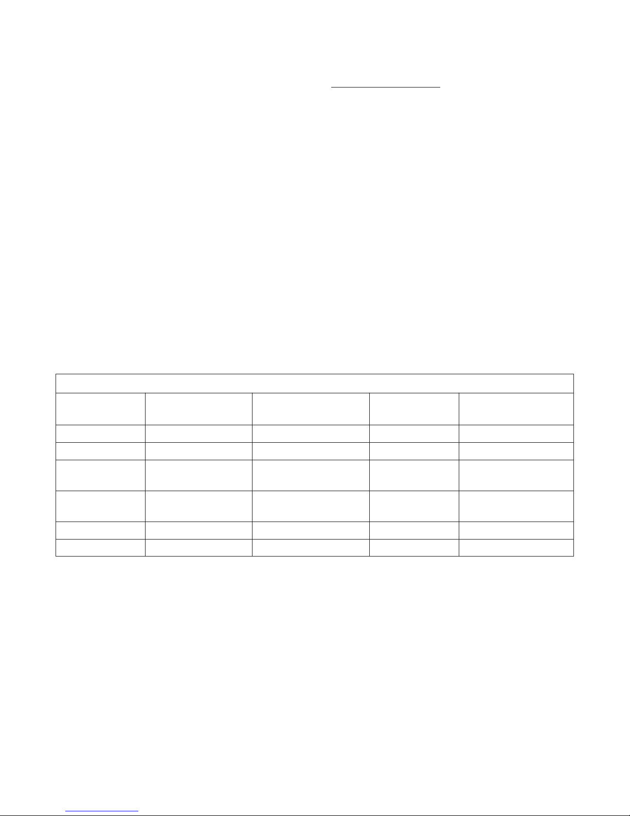
TVL 125/16/20/30
MODEL TYPE RAIL HEIGHT "A" FRAME WIDTH "B" BED HEIGHT ABOVE BED RANGE
RANGE
STANDARD 85 80 33-54 NA
STANDARD 85 90, 95, 100 33-56 NA
ABOVE BED 89 80 33-40 16-14
41-44 15-10
ABOVE BED 89 90, 95, 100 33-40 16
41-46 15-10
LOW BED 83 80 33-40 16-14
LOW BED 83 90, 95, 100 33-40 16
Table 1.

3.
INSTALLATION INST UCTIONS
Step 1 Inspect entire package of your new liftgate for obvious damage. Report any damage to
the freight line who delivered your liftgate. DO NOT REMOVE ANY BANDING!
Step 2 Locate the vehicle on which the liftgate is to be mounted on a dry and level floor and
open the rear door on the vehicle.
Step 3 Raise gate and place it against the rear of the vehicle and remove any obstructions
where possible. If obstruction can not be removed, use 4 spacers 12" long x 3" wide by
depth of interference and weld to top and bottom of rails. See figure 2. (If structural
angle or tubing is used for spacer, it must have a .25" minimum wall thickness). The
depth of the spacers may vary from top to bottom to enable a perpendicular mounting
to the ground. See figure 3.
Step 4 If the gate width does not match the width of the vehicle body, fabricate 4 adapters .25"
minimum wall thickness x 12" long. Weld adapters to the back side of liftgate's rails to
match location of body's rear corner posts as shown in figure 4.

4.
Step 5 If the truck's rear corner posts are aluminum, four steel angle brackets .25" minimum
wall thickness x 12" must be fabricated and attached as shown in figure 5. Bolt
brackets to rear of vehicle as required to support the load.

5.
Step 6 Raise lift and square it with the rear sill of vehicle as shown in figure 6. Temporary
supports as shown in figure 7 may be welded to cylinder housing to assist in squaring
lift to rear sill of vehicle.
Step 7 Center the liftgate on the truck body and tack weld frame of liftgate to rear sill and to
the rear post of body as shown in figure 8. DO NOT REMOVE FOR LIFT OR CRANE
UNTIL ALL WELDING IS COMPLETE!
Step 8 Review all mounting dimensions and be certain gate is square and centered with
respect to the body and rails are perpendicular to the ground.
Step 9 Weld rail adapters to vehicle body or where gate is attached directly to vehicle use
eight welds three inches long on each side of the rail. See figure 9.

6.
Step 10 If liftgate installation is on a flatbed vehicle, fabricate load bearing support tubes and
diagonal braces as shown in Figure 10. Square the support tubes with the bed and
perpendicular to the ground as shown, and weld braces to vehicle body and support
tubes. Then weld liftgate rails to support tubes on both the inside and outside corners
of each rail.
Step 11 Weld cylinder housing to rear of body payload area. Note: Some models have plastic
oil reservoirs on their power units. Necessary precautions must be taken during
welding to prevent heat damage to reservoirs on these models. Recheck all welds
and remove forklift or crane from liftgate. Remove lifting crossbar from rails and grind
rails smooth.
Step 12 If possible, install diagonal braces from the lower part of the rails to the vehicle body
(see Figure 11). On lower bed heights, the rails may need trimmed to maintain an
adequate 18" of ground clearance. NEVER trim the rails more than 25" from the
ground OR so high that lower nylon wear pads drop, EVEN PARTIALLY, out of rails,
which may cause liftgate to jam up or cause damage to liftgate (see Figure 11). This
25" maximum dimension MUST be measured on an unloaded truck, or this dimension
will be exceeded when the truck is unloaded. (On special orders, consult factory as
the allowable trim dimensions may vary from what is shown here).

7.
Step 13 Fasten the 150 AMP circuit breaker provided within 2 ft. of the truck battery. Route
battery cable from the pump enclosure toward the 150 AMP breaker. AVOID SHARP
CORNERS AND HIGH HEAT AREAS! Use cable clips provided to secure the cable to
the truck frame every 2 feet. Cut the cable to the desired length and strip .88" of
insulation from the end. Slide the pre-cut heat shrink over the end of the cable.
Secure the cable lug in a vise and apply heat to the connector and insert the cable as
the solder melts. Allow connector to cool and install the heat shrink. Attach this end to
one terminal on the 150 amp circuit breaker. Install heavy ground cable from negative
battery terminal to the frame. Wire the breaker to the truck battery using the 2ft. cable
provided. Bolt the grounding cable to the truck frame. See figure 12.
Step 14 Many late model trucks have battery connections as shown in figure 12. The ground
cable from the battery may be run directly to the engine block with only a light braided
ground strap connecting the block to the chassis. Where this is the case, the factory
installed cable usually does not provide an adequate ground circuit for operating
battery powered liftgates. We recommend that the cables labeled with an "X" be not
less than #2 gauge cable as supplied in the installation kit. Also because of the high
current draw (Approximately 200A) we recommend that the alternator be a heavy
duty type and the battery must have a 150 AMP minimum reserve capacity.

8.
Step 16 Platform manual closing torsion assist is preset at the factory, however, if it is
necessary to adjust the closing torsion, use the following steps to do so: (See figure
14)
A. Place the platform in the stowed(vertical) position making sure the platform stow
bars are secured in the resting plates on both sides of the liftgate.
B. Remove the .62" diameter retention bolt(A) from the center of the tension adjusting
bracket.
C. Place a .50" square breaker bar in the square hole of the tension adjusting
bracket.
D. Turn breaker bar counterclockwise to relieve the force on the .38" diameter bolt(B)
and remove bolt(B) noting the position of the tension adjusting bracket at the initial
setting.
Step 15 The TVLR above bed models are pre-set to travel 10 inches above bed. Depending
on the bed height it may be possible to obtain up to 16 inches above bed. Refer to
tables 1 and 2. To do this some of the lift chain must be removed. This amount is the
same as the additional travel desired. The platform must be completely lowered to the
ground and the cylinder housing cover removed. Remove the jam nuts and tension
rods attached to the chain and cut off the required amount from each chain. Push the
cylinder rod in and reassemble the tension rods and replace cover. Raise the platform
and check dimensions and adjust as necessary.

9.
E. To increase tension, use the breaker bar to rotate bracket counterclockwise
beyond its initial setting until the desired tension is reached. Line up a hole in the
adjusting bracket with one of the two holes in the slider and thread the .38"
diameter bolt (B) through the aligned holes to secure the desired setting.
F. Replace retention bolt(A) and tighten both bolts(A and B) securely.
Step 17 If the liftgate was mounted correctly to the truck, the platform should be parallel to the
ground in it's open position, however, if minor adjustments are required, simply
tighten adjusting nuts(A) On U-bolt(B) on platform block(C) to raise the ramp end of
the platform or to lower the ramp end simply loosen nuts(A). See figure 15. Similar
adjustments should be made on both sides of the platform so that both chains see
the same tension when loaded. CAUTION: U-BOLT(B) MUST REMAIN
COMPLETELY THREADED THROUGH NUTS(A).
Step 18 Set adjustment angles on either side of liftgate to hold platform vertical such that the

10.
stow bars on platform are aligned with the resting plate slots. Inspect alignment with
stow bars raised completely out of resting plate slots (See figure 4A). If they are out
of alignment, put the platform in the stored position. Raise platform slightly, so that
stow bars are not sitting on the bottom of the resting plate slot, so there is tension in
chains (See figure 4B). Then, unloosen screws on the adjustment angles and move
angles so they are tight against the vertical platform. Once angles are adjusted,
tighten screws. Be sure to do this for both sides. Repeat inspection of stow bar
alignment and readjust if necessary. Failure to keep stow bars aligned with resting
plate slots can result in excessive wear of stow bars and resting plates.
Step 19 Thieman recommends that the installer perform a weight test of the liftgate to check
the welds or mounting bolts and the structural integrity of the body or frame of the
truck or trailer. The load used should be the maximum weight rating of the particular
liftgate with the weight centrally located on the platform. A minimum of 20 cycles
should be made to insure the integrity of the mounting.
Step 20 If applying a finished coat of paint, mask off the openings in the vertical frame rails so
that no paint gets inside, where the I-beam sliders track up and down. WARNING:
OVERSPRAY IN RAILS CAN GET EMBEDDED IN NYLON WEAR PADS ON
SLIDERS, WHICH CAN CAUSE LIFTGATE TO NOT OPERATE SMOOTHLY. When
painting, carefully grease or mask fittings and exposed portion of the piston rod.
Finish paint as required and remove the pre-mask on decals already applied by
Thieman. Apply decals from installation kits in the appropriate locations as shown.
The decals MUST be applied or all warranties are VOID!

11.
Item Part Name Part Number
1 Warning Decal-center load 4682
2 Fast Idle Decal 4650150
3 Danger Decal-no riding 4609
4 Operating Decal 4650780
5 Capacity Decal 1250# 4650060
5 Capacity Decal 1600# 4650750
5 Capacity Decal 2000# 4650100
5 Capacity Decal 3000# 4650120
6 Caution Decal-pinch point 4650790
7 Caution Decal-cover 4650760
8 Caution Decal-working area 4650770
9 Reflector (3) 5705
10 Thieman Nameplate 4650801
11 Toggle Switch Decal(1) 4650820
12 Wiring Decal 4617
13 Warning Decal - High Pressure 4620
14 Lubrication Instruction Decal 4662
15 Lube Location Decal (4) 4663
16 Urgent Warning Decal 4681
Step 21 Any lights that were removed or obstructed must be replaced or relocated in such a
manner that the completed vehicle must be in compliance with FMVSS 108(49 CFR
571.108). If the liftgate was ordered with the optional light kit, refer to the light wiring
pictorial for wiring details.
INSPECTION AND LOCATION OF DECALS
Inspect all decals listed below to be certain they are in the proper location and are legible.
ALL DECALS MUST BE IN PLACE AND LEGIBLE OR ALL WARRANTIES ARE VOID!

10/17 • 1M • MP94021
LIGHT WI ING PICTO IAL
Other manuals for TVLR 125
1
This manual suits for next models
3
Table of contents