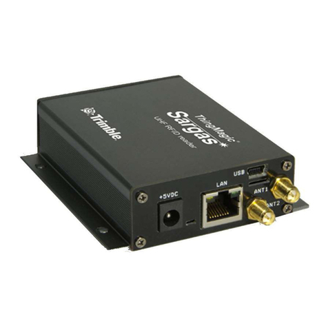
ThingMagic Mercury6e M6e-30dBm Installation instructions

M6e-31.5dBm Hardware Guide
For: M6e (Firmware Ver. 1.7 and later)

Government Limited Rights Notice:
All documentation and manuals were developed at private expense and
no part of it was developed using Government funds.
The U.S. Government’s rights to use, modify, reproduce, release, perform,
display, or disclose the technical data contained herein are restricted by
paragraph (b)(3) of the Rights in Technical Data — Noncommercial Items
clause (DFARS 252.227-7013(b)(3)), as amended from time-to-time. Any
reproduction of technical data or portions thereof marked with this legend
must also reproduce the markings. Any person, other than the U.S.
Government, who has been provided access to such data must promptly
notify ThingMagic, Inc.
ThingMagic, Mercury, Reads Any Tag, and the ThingMagic logo are
trademarks or registered trademarks of ThingMagic, A Division of Trimble.
Other product names mentioned herein may be trademarks or registered
trademarks of Trimble or other companies.
©2011 ThingMagic – a division of Trimble Navigation Limited. ThingMagic
and The Engine in RFID are registered trademarks of Trimble Navigation
Limited. Other marks may be protected by their respective owners. All
Rights Reserved.d
ThingMagic, A Division of Trimble
One Cambridge Center, 11th floor
Cambridge, MA 02142
866-833-4069
02 Revision 2
February, 2011

3
Revision Table
Date Version Description
4/2010 01 RevA First Draft for Beta release
8/2010 01 RevB • Updated GPIO content
• Added FCC regulation info section
2/2011 02 Rev2 • updated content to meet regulatory requirements

4

Mercury Embedded Modules Developer’s Guide 5
Contents
Communication Regulation Information . . . . . . . . . . . . . . . . . . . . . . . . . . . . . . . . . . . . . . . . . . . . . . . . . . . . . . . 9
Federal Communication Commission Interference Statement . . . . . . . . . . . . . . . . . . . . . . . . . . . . . . . . . . 9
Industry Canada . . . . . . . . . . . . . . . . . . . . . . . . . . . . . . . . . . . . . . . . . . . . . . . . . . . . . . . . . . . . . . . . . . . . . . 11
Industrie Canada 12
Mercury6e Introduction . . . . . . . . . . . . . . . . . . . . . . . . . . . . . . . . . . . . . . . . . . . . . . . . . . . . . .13
Hardware Overview . . . . . . . . . . . . . . . . . . . . . . . . . . . . . . . . . . . . . . . . . . . . . . . . . . . . . . . . .15
Hardware Interfaces . . . . . . . . . . . . . . . . . . . . . . . . . . . . . . . . . . . . . . . . . . . . . . . . . . . . . . . . . . . . . . . . . . . . . . . .16
Antenna Connections . . . . . . . . . . . . . . . . . . . . . . . . . . . . . . . . . . . . . . . . . . . . . . . . . . . . . . . . . . . . . . . . . . 16
Antenna Requirements 16
Digital/Power Connector . . . . . . . . . . . . . . . . . . . . . . . . . . . . . . . . . . . . . . . . . . . . . . . . . . . . . . . . . . . . . . . 16
Control Signal Specification 17
General Purpose Input/Output (GPIO) 19
Reset Line 20
Power Requirements. . . . . . . . . . . . . . . . . . . . . . . . . . . . . . . . . . . . . . . . . . . . . . . . . . . . . . . . . . . . . . . . . . . . . . . .21
RF Power Output . . . . . . . . . . . . . . . . . . . . . . . . . . . . . . . . . . . . . . . . . . . . . . . . . . . . . . . . . . . . . . . . . . . . . 21
Power Settings for Authorized Antennas and Cables 21
Power Supply Ripple . . . . . . . . . . . . . . . . . . . . . . . . . . . . . . . . . . . . . . . . . . . . . . . . . . . . . . . . . . . . . . . . . . 22
Power Consumption . . . . . . . . . . . . . . . . . . . . . . . . . . . . . . . . . . . . . . . . . . . . . . . . . . . . . . . . . . . . . . . . . . . 22
Environmental Specifications . . . . . . . . . . . . . . . . . . . . . . . . . . . . . . . . . . . . . . . . . . . . . . . . . . . . . . . . . . . . . . . .24
Operating Temperature . . . . . . . . . . . . . . . . . . . . . . . . . . . . . . . . . . . . . . . . . . . . . . . . . . . . . . . . . . . . . . . . 24
Electro-Static Discharge (ESD) Specification . . . . . . . . . . . . . . . . . . . . . . . . . . . . . . . . . . . . . . . . . . . . . . 24
Assembly Information . . . . . . . . . . . . . . . . . . . . . . . . . . . . . . . . . . . . . . . . . . . . . . . . . . . . . . . . . . . . . . . . . . . . . . . 25
Cables and Connectors . . . . . . . . . . . . . . . . . . . . . . . . . . . . . . . . . . . . . . . . . . . . . . . . . . . . . . . . . . . . . . . . 25
Digital Interface 25
Antennas 25
M6e Mechanical Drawing. . . . . . . . . . . . . . . . . . . . . . . . . . . . . . . . . . . . . . . . . . . . . . . . . . . . . . . . . . . . . . . 26
Authorized Antennas. . . . . . . . . . . . . . . . . . . . . . . . . . . . . . . . . . . . . . . . . . . . . . . . . . . . . . . . . . . . . . . . . . . . . . . .27
Authorized Cables . . . . . . . . . . . . . . . . . . . . . . . . . . . . . . . . . . . . . . . . . . . . . . . . . . . . . . . . . . . . . . . . . . . . . . . . . .28

6Mercury Embedded Modules Developer’s Guide
Firmware Overview. . . . . . . . . . . . . . . . . . . . . . . . . . . . . . . . . . . . . . . . . . . . . . . . . . . . . . . . . .29
Boot Loader . . . . . . . . . . . . . . . . . . . . . . . . . . . . . . . . . . . . . . . . . . . . . . . . . . . . . . . . . . . . . . . . . . . . . . . . . . . . . . . . 30
Application Firmware . . . . . . . . . . . . . . . . . . . . . . . . . . . . . . . . . . . . . . . . . . . . . . . . . . . . . . . . . . . . . . . . . . . . . . .31
Programming the M6e . . . . . . . . . . . . . . . . . . . . . . . . . . . . . . . . . . . . . . . . . . . . . . . . . . . . . . . . . . . . . . . . . 31
Upgrading the M6e. . . . . . . . . . . . . . . . . . . . . . . . . . . . . . . . . . . . . . . . . . . . . . . . . . . . . . . . . . . . . . . . . . . . 31
Verifying Application Firmware Image . . . . . . . . . . . . . . . . . . . . . . . . . . . . . . . . . . . . . . . . . . . . . . . . . . . . . 31
Custom On-Reader Applications . . . . . . . . . . . . . . . . . . . . . . . . . . . . . . . . . . . . . . . . . . . . . . . . . . . . . . . . . . . . . 32
Communication Protocol. . . . . . . . . . . . . . . . . . . . . . . . . . . . . . . . . . . . . . . . . . . . . . . . . . . . .33
Serial Communication Protocol . . . . . . . . . . . . . . . . . . . . . . . . . . . . . . . . . . . . . . . . . . . . . . . . . . . . . . . . . . . . . .34
Host-to-Reader Communication . . . . . . . . . . . . . . . . . . . . . . . . . . . . . . . . . . . . . . . . . . . . . . . . . . . . . . . . . 34
Reader-to-Host Communication . . . . . . . . . . . . . . . . . . . . . . . . . . . . . . . . . . . . . . . . . . . . . . . . . . . . . . . . . 35
CCITT CRC-16 Calculation 35
User Programming Interface. . . . . . . . . . . . . . . . . . . . . . . . . . . . . . . . . . . . . . . . . . . . . . . . . . . . . . . . . . . . . . . . . 36
Functionality of the Mercury6e . . . . . . . . . . . . . . . . . . . . . . . . . . . . . . . . . . . . . . . . . . . . . . .37
Regulatory Support . . . . . . . . . . . . . . . . . . . . . . . . . . . . . . . . . . . . . . . . . . . . . . . . . . . . . . . . . . . . . . . . . . . . . . . . .38
Supported Regions. . . . . . . . . . . . . . . . . . . . . . . . . . . . . . . . . . . . . . . . . . . . . . . . . . . . . . . . . . . . . . . . . . . . 38
Frequency Setting. . . . . . . . . . . . . . . . . . . . . . . . . . . . . . . . . . . . . . . . . . . . . . . . . . . . . . . . . . . . . . . . . . . . . 38
Frequency Units 39
Frequency Hop Table . . . . . . . . . . . . . . . . . . . . . . . . . . . . . . . . . . . . . . . . . . . . . . . . . . . . . . . . . . . . . . . . . . 39
Protocol Support . . . . . . . . . . . . . . . . . . . . . . . . . . . . . . . . . . . . . . . . . . . . . . . . . . . . . . . . . . . . . . . . . . . . . . . . . . . 40
ISO 18000-6C (Gen2). . . . . . . . . . . . . . . . . . . . . . . . . . . . . . . . . . . . . . . . . . . . . . . . . . . . . . . . . . . . . . . . . 40
Protocol Configuration Options 40
Protocol Specific Functionality 41
I-PX. . . . . . . . . . . . . . . . . . . . . . . . . . . . . . . . . . . . . . . . . . . . . . . . . . . . . . . . . . . . . . . . . . . . . . . . . . . . . . . . . 41
Protocol Configuration Options 41
ISO 18000-6B . . . . . . . . . . . . . . . . . . . . . . . . . . . . . . . . . . . . . . . . . . . . . . . . . . . . . . . . . . . . . . . . . . . . . . . 41
Protocol Configuration Options 41
Antenna Ports . . . . . . . . . . . . . . . . . . . . . . . . . . . . . . . . . . . . . . . . . . . . . . . . . . . . . . . . . . . . . . . . . . . . . . . . . . . . . . 42
Using a Multiplexer . . . . . . . . . . . . . . . . . . . . . . . . . . . . . . . . . . . . . . . . . . . . . . . . . . . . . . . . . . . . . . . . . . . . 42
Port Power and Settling Time . . . . . . . . . . . . . . . . . . . . . . . . . . . . . . . . . . . . . . . . . . . . . . . . . . . . . . . . . . . 44
Tag Handling . . . . . . . . . . . . . . . . . . . . . . . . . . . . . . . . . . . . . . . . . . . . . . . . . . . . . . . . . . . . . . . . . . . . . . . . . . . . . . .46
Tag Buffer . . . . . . . . . . . . . . . . . . . . . . . . . . . . . . . . . . . . . . . . . . . . . . . . . . . . . . . . . . . . . . . . . . . . . . . . . . . 46
Tag Streaming 46
Tag Read Meta Data . . . . . . . . . . . . . . . . . . . . . . . . . . . . . . . . . . . . . . . . . . . . . . . . . . . . . . . . . . . . . . . . . . . . . . . .47
Power Management. . . . . . . . . . . . . . . . . . . . . . . . . . . . . . . . . . . . . . . . . . . . . . . . . . . . . . . . . . . . . . . . . . . . . . . . . 48
Power Modes . . . . . . . . . . . . . . . . . . . . . . . . . . . . . . . . . . . . . . . . . . . . . . . . . . . . . . . . . . . . . . . . . . . . . . . . 48

Mercury Embedded Modules Developer’s Guide 7
Transmit Modes. . . . . . . . . . . . . . . . . . . . . . . . . . . . . . . . . . . . . . . . . . . . . . . . . . . . . . . . . . . . . . . . . . . . . . . 48
DRM Compliant Mode 49
Power Save Mode (non-DRM Compliant) 49
Performance Characteristics. . . . . . . . . . . . . . . . . . . . . . . . . . . . . . . . . . . . . . . . . . . . . . . . . . . . . . . . . . . . . . . . .50
Event Response Times . . . . . . . . . . . . . . . . . . . . . . . . . . . . . . . . . . . . . . . . . . . . . . . . . . . . . . . . . . . . . . . . . 50
Save and Restore Configuration . . . . . . . . . . . . . . . . . . . . . . . . . . . . . . . . . . . . . . . . . . . . . . . . . . . . . . . . . . . . .51
Appendix A: Error Messages . . . . . . . . . . . . . . . . . . . . . . . . . . . . . . . . . . . . . . . . . . . . . . . . .53
Common Error Messages . . . . . . . . . . . . . . . . . . . . . . . . . . . . . . . . . . . . . . . . . . . . . . . . . . . . . . . . . . . . . . . . . . .53
FAULT_MSG_WRONG_NUMBER_OF_DATA – (100h) 53
FAULT_INVALID_OPCODE – (101h) 54
FAULT_UNIMPLEMENTED_OPCODE – 102h 54
FAULT_MSG_POWER_TOO_HIGH – 103h 54
FAULT_MSG_INVALID_FREQ_RECEIVED (104h) 55
FAULT_MSG_INVALID_PARAMETER_VALUE - (105h) 55
FAULT_MSG_POWER_TOO_LOW - (106h) 55
FAULT_UNIMPLEMENTED_FEATURE - (109h) 56
FAULT_INVALID_BAUD_RATE - (10Ah) 56
Bootloader Faults. . . . . . . . . . . . . . . . . . . . . . . . . . . . . . . . . . . . . . . . . . . . . . . . . . . . . . . . . . . . . . . . . . . . . . . . . . . 57
FAULT_BL_INVALID_IMAGE_CRC – 200h 57
FAULT_BL_INVALID_APP_END_ADDR – 201h 57
Flash Faults . . . . . . . . . . . . . . . . . . . . . . . . . . . . . . . . . . . . . . . . . . . . . . . . . . . . . . . . . . . . . . . . . . . . . . . . . . . . . . . .58
FAULT_FLASH_BAD_ERASE_PASSWORD – 300h 58
FAULT_FLASH_BAD_WRITE_PASSWORD – 301h 58
FAULT_FLASH_UNDEFINED_ERROR – 302h 59
FAULT_FLASH_ILLEGAL_SECTOR – 303h 59
FAULT_FLASH_WRITE_TO_NON_ERASED_AREA – 304h 59
FAULT_FLASH_WRITE_TO_ILLEGAL_SECTOR – 305h 59
FAULT_FLASH_VERIFY_FAILED – 306h 60
Protocol Faults . . . . . . . . . . . . . . . . . . . . . . . . . . . . . . . . . . . . . . . . . . . . . . . . . . . . . . . . . . . . . . . . . . . . . . . . . . . . .61
FAULT_NO_TAGS_FOUND – (400h) 62
FAULT_NO_PROTOCOL_DEFINED – 401h 62
FAULT_INVALID_PROTOCOL_SPECIFIED – 402h 62
FAULT_WRITE_PASSED_LOCK_FAILED – 403h 63
FAULT_PROTOCOL_NO_DATA_READ – 404h 63
FAULT_AFE_NOT_ON – 405h 63
FAULT_PROTOCOL_WRITE_FAILED – 406h 64
FAULT_NOT_IMPLEMENTED_FOR_THIS_PROTOCOL – 407h 64
FAULT_PROTOCOL_INVALID_WRITE_DATA – 408h 64

8Mercury Embedded Modules Developer’s Guide
FAULT_PROTOCOL_INVALID_ADDRESS – 409h 64
FAULT_GENERAL_TAG_ERROR – 40Ah 65
FAULT_DATA_TOO_LARGE – 40Bh 65
FAULT_PROTOCOL_INVALID_KILL_PASSWORD – 40Ch 65
FAULT_PROTOCOL_KILL_FAILED - 40Eh 65
FAULT_PROTOCOL_BIT_DECODING_FAILED - 40Fh 66
FAULT_PROTOCOL_INVALID_EPC – 410h 66
FAULT_PROTOCOL_INVALID_NUM_DATA – 411h 66
FAULT_GEN2 PROTOCOL_OTHER_ERROR - 420h 66
FAULT_GEN2_PROTOCOL_MEMORY_OVERRUN_BAD_PC - 423h 67
FAULT_GEN2 PROTOCOL_MEMORY_LOCKED - 424h 67
FAULT_GEN2 PROTOCOL_INSUFFICIENT_POWER - 42Bh 67
FAULT_GEN2 PROTOCOL_NON_SPECIFIC_ERROR - 42Fh 68
FAULT_GEN2 PROTOCOL_UNKNOWN_ERROR - 430h 68
Analog Hardware Abstraction Layer Faults. . . . . . . . . . . . . . . . . . . . . . . . . . . . . . . . . . . . . . . . . . . . . . . . . . . . 69
FAULT_AHAL_INVALID_FREQ – 500h 69
FAULT_AHAL_CHANNEL_OCCUPIED – 501h 69
FAULT_AHAL_TRANSMITTER_ON – 502h 69
FAULT_ANTENNA_NOT_CONNECTED – 503h 69
FAULT_TEMPERATURE_EXCEED_LIMITS – 504h 70
FAULT_POOR_RETURN_LOSS – 505h 70
FAULT_AHAL_INVALID_ANTENA_CONFIG – 507h 70
Tag ID Buffer Faults . . . . . . . . . . . . . . . . . . . . . . . . . . . . . . . . . . . . . . . . . . . . . . . . . . . . . . . . . . . . . . . . . . . . . . . . 72
FAULT_TAG_ID_BUFFER_NOT_ENOUGH_TAGS_AVAILABLE – 600h 72
FAULT_TAG_ID_BUFFER_FULL – 601h 72
FAULT_TAG_ID_BUFFER_REPEATED_TAG_ID – 602h 72
FAULT_TAG_ID_BUFFER_NUM_TAG_TOO_LARGE – 603h 73
System Errors . . . . . . . . . . . . . . . . . . . . . . . . . . . . . . . . . . . . . . . . . . . . . . . . . . . . . . . . . . . . . . . . . . . . . . . . . . . . . . 74
FAULT_SYSTEM_UNKNOWN_ERROR – 7F00h 74
FAULT_TM_ASSERT_FAILED – 7F01h 74
Appendix B: Getting Started - Devkit. . . . . . . . . . . . . . . . . . . . . . . . . . . . . . . . . . . . . . . . . .75
Devkit USB Interfaces. . . . . . . . . . . . . . . . . . . . . . . . . . . . . . . . . . . . . . . . . . . . . . . . . . . . . . . . . . . . . . . . . . . . . . . 75
USB/RS232 . . . . . . . . . . . . . . . . . . . . . . . . . . . . . . . . . . . . . . . . . . . . . . . . . . . . . . . . . . . . . . . . . . . . . . . . . 75
Native USB . . . . . . . . . . . . . . . . . . . . . . . . . . . . . . . . . . . . . . . . . . . . . . . . . . . . . . . . . . . . . . . . . . . . . . . . . . 75
Demo Application. . . . . . . . . . . . . . . . . . . . . . . . . . . . . . . . . . . . . . . . . . . . . . . . . . . . . . . . . . . . . . . . . . . . . . . . . . . 77
Demo Tool Notes . . . . . . . . . . . . . . . . . . . . . . . . . . . . . . . . . . . . . . . . . . . . . . . . . . . . . . . . . . . . . . . . . . . . . 77

Communication Regulation Information
9
Communication Regulation Information
WARNING!
Operation of the M6e module requires professional installation to
correctly set the TX power for the RF cable and antenna selected.
EMC FCC 47 CFR, Part 15
Industrie Canada RSS-210
Federal Communication Commission Interference Statement
This equipment has been tested and found to comply with the limits for a Class B
digital device, pursuant to Part 15 of the FCC Rules. These limits are designed to
provide reasonable protection against harmful interference in a residential installation.
This equipment generates uses and can radiate radio frequency energy and, if not
installed and used in accordance with the instructions, may cause harmful interference to
radio communications. However, there is no guarantee that interference will not occur in a
particular installation. If this equipment does cause harmful interference to radio or
television reception, which can be determined by turning the equipment off and on, the
user is encouraged to try to correct the interference by one of the following measures:
Reorient or relocate the receiving antenna.
Increase the separation between the equipment and receiver.
Connect the equipment into an outlet on a circuit different from that to which the
receiver is connected.
Consult the dealer or an experienced radio/TV technician for help.
This device complies with Part 15 of the FCC Rules. Operation is subject to the following
two conditions: (1) This device may not cause harmful interference, and (2) this device
must accept any interference received, including interference that may cause undesired
operation.
FCC Caution: Any changes or modifications not expressly approved by the party
responsible for compliance could void the user's authority to operate this equipment.
This transmitter module is authorized to be used in other devices only by OEM
integrators under the following conditions:
1. The antenna(s) must be installed such that a minimum separation distance of 25cm is
maintained between the radiator (antenna) & user’s/nearby people’s body at all
times.

Communication Regulation Information
10
2. The transmitter module must not be co-located with any other antenna or transmitter.
As long as the two conditions above are met, further transmitter testing will not be
required. However, the OEM integrator is still responsible for testing their end-product for
any additional compliance requirements required with this module installed (for example,
digital device emissions, PC peripheral requirements, etc.).
Note
In the event that these conditions can not be met (for certain configurations
or co-location with another transmitter), then the FCC authorization is no
longer considered valid and the FCC ID can not be used on the final product.
In these circumstances, the OEM integrator will be responsible for re-
evaluating the end product (including the transmitter) and obtaining a
separate FCC authorization.
The OEM integrator has to be aware not to provide information to the end user regarding
how to install or remove this RF module in the user manual of the end product.
User Manual Requirement
The user manual for the end product must include the following information in a
prominent location;
“To comply with FCC’s RF radiation exposure requirements, the antenna(s) used for this
transmitter must be installed such that a minimum separation distance of 25cm is
maintained between the radiator (antenna) & user’s/nearby people’s body at all times and
must not be co-located or operating in conjunction with any other antenna or transmitter.”
AND
“The transmitting portion of this device carries with it the following two warnings:
“This device complies with Part 15....”
AND
“Any changes or modifications to the transmitting module not expressly approved by
ThingMagic Inc. could void the user’s authority to operate this equipment” “
End Product Labeling
The final end product must be labeled in a visible area with the following:
“Contains Transmitter Module FCC ID: QV5MERCURY6E-A”

Communication Regulation Information
11
or
“Contains FCC ID: QV5MERCURY6E-A.”
Industry Canada
Under Industry Canada regulations, this radio transmitter may only operate using an
antenna of a type and maximum (or lesser) gain approved for the transmitter by Industry
Canada. To reduce potential radio interference to other users, the antenna type and its
gain should be so chosen that the equivalent isotropically radiated power (e.i.r.p.) is not
more than that necessary for successful communication.
This radio transmitter (identify the device by certification number, or model number if
Category II) has been approved by Industry Canada to operate with the antenna types
listed below with the maximum permissible gain and required antenna impedance for
each antenna type indicated. Antenna types not included in this list, having a gain greater
than the maximum gain indicated for that type, are strictly prohibited for use with this
device
Operation is subject to the following two conditions: (1) this device may not cause
interference, and (2) this device must accept any interference, including interference that
may cause undesired operation of the device.
To reduce potential radio interference to other users, the antenna type and its gain should
be so chosen that the equivalent isotropically radiated power (e.i.r.p.) is not more than
that permitted for successful communication.
This device has been designed to operate with the antennas and cables listed in
Authorized Antennas and Authorized Cables tables. Antennas or cables not included in
these lists are strictly prohibited for use with this device.
To comply with IC RF exposure limits for general population/uncontrolled exposure, the
antenna(s) used for this transmitter must be installed to provide a separation distance of
at least 25 cm from all persons and must not be collocated or operating in conjunction
with any other antenna or transmitter.
End Product Labeling
The final end product must be labeled in a visible area with the following:
“Contains ThingMagic Inc. Mercury6e (or appropriate model number you’re filing with IC)
transmitting module FCC ID: QV5MERCURY6E-A (IC: 5407A-MERCURY6EA)”

Communication Regulation Information
12
Industrie Canada
Conformément à la réglementation d'Industrie Canada, le présent émetteur radio peut
fonctionner avec une antenne d'un type et d'un gain maximal (ou inférieur) approuvé pour
l'émetteur par Industrie Canada. Dans le but de réduire les risques de brouillage
radioélectrique à l'intention des autres utilisateurs, il faut choisir le type d'antenne et son
gain de sorte que la puissance isotrope rayonnée équivalente (p.i.r.e.) ne dépasse pas
l'intensité nécessaire à l'établissement d'une communication satisfaisante.
Le présent émetteur radio (identifier le dispositif par son numéro de certification ou son
numéro de modèle s'il fait partie du matériel de catégorie I) a été approuvé par Industrie
Canada pour fonctionner avec les types d'antenne énumérés ci-dessous et ayant un gain
admissible maximal et l'impédance requise pour chaque type d'antenne. Les types
d'antenne non inclus dans cette liste, ou dont le gain est supérieur au gain maximal
indiqué, sont strictement interdits pour l'exploitation de l'émetteur
Le fonctionnement de l’ appareil est soumis aux deux conditions suivantes:
1. Cet appareil ne doit pas perturber les communications radio, et
2. cet appareil doit supporter toute perturbation, y compris les perturbations qui
pourraient provoquer son dysfonctionnement.
Pour réduire le risque d'interférence aux autres utilisateurs, le type d'antenne et son gain
doivent être choisis de façon que la puissance isotrope rayonnée équivalente (PIRE) ne
dépasse pas celle nécessaire pour une communication réussie.
L’ appareil a été conçu pour fonctionner avec les antennes et les câbles énumérés dans
les tables Antennes Autorisées et Câbles Autorisés. Il est strictement interdit de l’ utiliser
l’ appareil avec des antennes ou câbles qui ne sont pas inclus dans ces listes.
Au but de conformer aux limites d'exposition RF pour la population générale (exposition
non-contrôlée), les antennes utilisés doivent être installés à une distance d'au moins 25
cm de toute personne et ne doivent pas être installé en proximité ou utilisé en conjonction
avec un autre antenne ou transmetteur.
Marquage sur l’ étiquette du produit complet dans un endroit visible: "Contient
ThingMagic transmetteur, FCC ID: QV5MERCURY6E-A (IC:5407A-MERCURY6EA)"

Mercury6e Introduction 13
Mercury6e Introduction
The ThingMagic®Mercury6e®(M6e) embedded module is an RFID engines that you can
integrate with other systems to create RFID-enabled products.
Applications to control the M6e modules and derivative products can be written using the
high level MercuryAPI. The MercuryAPI supports Java, .NET and C programming
environments. The MercuryAPI Software Development Kit (SDK) contains sample
applications and source code to help developers get started demoing and developing
functionality. For more information on the MercuryAPI see the MercuryAPI Programmers
Guide and the MercuryAPI SDK, available on the ThingMagic website.
This document is for hardware designers and software developers. It describes the
hardware specifications and firmware functionality and provides guidance on how to
incorporate the M6e module within a third-party host system. The rest of the document is
broken down into the following sections:
Hardware Overview - This section provides detailed specifications of the M6e
hardware. This section should be read in its entirety before designing hardware or
attempting to operate the M6e module in hardware other than the ThingMagic
DevKit.
Firmware Overview - This section describes provides a detailed description of the M6e
firmware components including the bootloader and application firmware.
Communication Protocol - This section provides an overview of the low level serial
communications protocol used by the M6e.
Functionality of the Mercury6e - This section provides detailed descriptions of the M6e
features and functionality that are supported through the use of the MercuryAPI.
Appendix A: Error Messages - This appendix lists and provides causes and suggested
solutions for M6e Error Codes.
Appendix B: Getting Started - Devkit - QuickStart guide to getting connected to the M6e
Developer’s Kit and using the Demo Applications included with the MercuryAPI SDK.

14 Mercury6e Introduction

Hardware Interfaces
16 Hardware Overview
Hardware Interfaces
Antenna Connections
The M6e supports four monostatic bidirectional RF antennas through four MMCX
connectors: labeled J1 through J4 on the module. See Cables and Connectors for more
information on antenna connector parts.
The maximum RF power that can be delivered to a 50 ohm load from each port is 1.4
Watts, or +31.5 dBm (operation above 30dBm requires a professional installer).
Note
The RF ports can only be energized one at a time.
Antenna Requirements
The performance of the M6e is affected by antenna quality. Antennas that provide good
50 ohm match at the operating frequency band perform best. Specified sensitivity
performance is achieved with antennas providing 17 dB return loss or better across the
operating band. Damage to the module will not occur for any return loss of 1 dB or
greater. Damage may occur if antennas are disconnected during operation or if the
module sees an open or short circuit at its antenna port.
Antenna Detection
To minimize the chance of damage due to antenna disconnection, the M6e supports
antenna detection. Detection can be done automatically or manually, the choice of which
is configured through API calls. Regardless of how it’s used it is generally recommend
that antenna detection be enabled as it helps protect the module from possible damage
due to return losses less than 1 dB.
Digital/Power Connector
The digital connector provides power, serial communications signals, shutdown and reset
signals to the M6e module, and access to the GPIO inputs and outputs. These signals are
provided through connector part number: Molex 53261-1571 - 1.25mm pin centers, 1

Hardware Interfaces
Hardware Overview 17
amp per pin rating. which mates with Molex housing p/n 51021-1500 with crimps p/n
63811-0300. See Cables and Connectors for more information on typical cable parts.
Control Signal Specification
TTL Level UART Interface
The module communicates to a host processor via a TTL logic level UART serial port or
via a USB port. Both ports are accessed on the 15-pin Digital/Power Connector. The TTL
logic level UART supports complete functionality. The USB port supports complete
functionality except the lowest power operational mode.
Note
Power Consumption specifications apply to control via the TTL UART.
M6e Digital Connector Signal Definition
Molex
53261-1571
Pin Number
Signal
Signal
Direction
(In/Out of M6e)
Notes
1 GND P/S Return Must connect both GND pins to ground
2 GND P/S Return
3 +5VDC P/S Input Must connect both 5V supplies
4 +5 VDC P/S Input
5 GPIO1 Bi-directional Input 5VDC tolerant, 16mA Source/Sink
6 GPIO2 Bi-directional
7 GPIO3 Bi-directional
8 GPIO4 Bi-directional
9 UART_RX_TTL In In + 10k Ohm to Ground
10 UART_TX_TTL Out Out
11 USB_DM Bi-directional USB Data (D-) signal
12 USB_DP Bi-directional USB Data (D+) signal
13 USB_5VSENSE In Input 5V to tell module to talk on USB
14 SHUTDOWN In Disable all 5V Inputs
15 RESET Bi-directional HIGH output indicates Boot Loader is running
LOW output indicates Application Firmware is
running
Note: Not 5V tolerant.

Hardware Interfaces
18 Hardware Overview
TTL Level TX
V-Low: Max 0.4 VDC
V-High: 2.1 to 3.3 VDC
8 mA max
TTL Level RX
V-Low: -0.3 to 0.6 VDC
V-High: 2.2 to 5 VDC
(Tied to ground through a 10kOhm pull-up resistor. It is not harmful, but not
recommended to drive the input above 3.3 V.)
A level converter could be necessary to interface to other devices that use standard 12V
RS232. Only three pins are required for serial communication (TX, RX, and GND).
Hardware handshaking is not supported. The M6e serial port has an interrupt-driven
FIFO that empties into a circular buffer.
The connected host processor’s receiver must have the capability to receive up to 256
bytes of data at a time without overflowing.
Baud rates supported:
– 9600
– 19200
– 38400
– 115200
– 230400
– 460800
– 921600
Note
The baudrate in the Boot Loader mode depends on whether the module
entered the bootloader mode after a power-up or through an assert or “boot
bootloader” user command. Upon power up if the Reset Line is LOW then the
default baud rate of 9600 will be used. If the module returns to the
bootloader from Application Firmware mode, then the current state and
baudrate will be retained.
USB Interface
Supports USB 2.0 full speed device port (12 Megabits per second) using the two USB
pins (USB_DM and USB_DP).

Hardware Interfaces
Hardware Overview 19
General Purpose Input/Output (GPIO)
The four GPIO connections, provided through the M6e Digital Connector Signal Definition,
may be configured as inputs or outputs using the MercuryAPI. The GPIO pins connect
through 100 ohm resistors to the high current PA0 to PA3 pins of the AT91SAM7X
processor. The processor data sheet can be consulted for additional details.
Pins configured as inputs must not have input voltages that exceed voltage range of -0.3
volts to +5.5 volts. In addition, during reset the input voltages should not exceed 3.3V.
Outputs may source and sink 16 mA. Voltage drop in the series 100 ohm resistor will
reduce the delivered voltage swing for output loads that draw significant current.
Input Mode
– TTL compatible inputs,
– Logic low < 0.8 V,
– Logic high > 2.0V.
– 5V tolerant
Output Mode
– 3.3 Volt CMOS Logic Output with 100 ohms in series.
– Greater than 1.9 Volts when sourcing 8 mA.
– Greater than 2.9 Volts when sourcing 0.3 mA.
– Less than 1.2 Volts when sinking 8 mA.
– Less than 0.2 Volts when sinking 0.3 mA.
Module power consumption can be adversely affected by incorrect GPIO configuration.
Similarly, the power consumption of external equipment connected to the GPIOs can also
be adversely affected. The following instructions will yield specification compliant
operation.
On power up, the M6E module configures its GPIOs as outputs to avoid contention from
user equipment that may be driving those lines. The input configuration is as a 3.3 volt
logic CMOS input and will have a leakage current not in excess of 400 nA. The input is in
an undetermined logic level unless pulled externally to a logic high or low. Module power
consumption for floating inputs is unspecified. With the GPIOs configured as inputs
and individually pulled externally to either high or low logic level, module power
consumption is as listed in the M6e Power Consumption table.
GPIOs may be reconfigured individually after power up to become outputs. This
configuration takes effect either at API execution or a few tens of milliseconds after power
up if the configuration is stored in nonvolatile memory. The configuration to outputs is

Hardware Interfaces
20 Hardware Overview
defeated if the module is held in the boot loader by Reset Line being held low. Lines
configured as outputs consume no excess power if the output is left open. Specified
module power consumption is achieved for one or more GPIO lines set as output and left
open. Users who are not able to provide external pull ups or pull downs on any given
input, and who do not need that GPIO line, may configure it as an output and leave it
open to achieve specified module power consumption.
Configuring GPIO Settings
The GPIO lines are configured as inputs or outputs through the MercuryAPI by setting the
reader configuration parameters /reader/gpio/inputList and /reader/gpio/outputList. Once
configured as inputs or outputs the state of the lines can be Get or Set using the gpiGet()
and gpoSet() methods, respectively. See the language specific reference guide for more
details.
Reset Line
Upon power up the RESET (pin 15) line is configured as an input. The input value will
determine whether the Boot Loader will wait for user commands or immediately load the
Application Firmware image and enter application mode. After that action is completed, this
line is configured as an output line. While the unit continues to be in bootloader the line is
driven high.
Once in application mode, the RESET line is driven low. if the module returns to the
bootloader mode, either due to an assert or “boot bootloader”, the RESET line will again
be driven high.
To minimize power consumption in the application, the RESET line should be either left
open or pulled weakly low (10k to ground).
Other manuals for Mercury6e M6e-30dBm
1
This manual suits for next models
1
Table of contents
Other ThingMagic RFID System manuals
Popular RFID System manuals by other brands
Dormakaba
Dormakaba SP320 user manual
Stid
Stid ARCS-A/BT1 installation instructions
Siemens
Siemens Simatic RF600 Configuration manual
Feig Electronic
Feig Electronic OBID classic-pro ID CPR.02.10-AD installation manual

Rockwell Automation
Rockwell Automation Allen-Bradley 58UHF user manual
CSL
CSL CS468 user manual

