© 2012 Thorlabs4
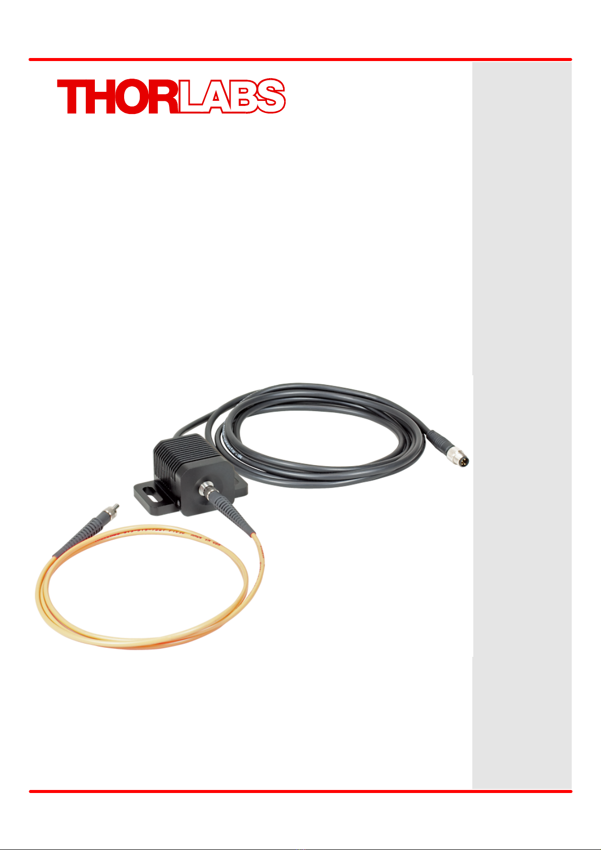
MxxxF1 Series
2 Operating Instruction
Take care for air ventilation in order to avoid overheating of the LED. Increased temperature
leads to optical power drop and shortened life time.
Note
Optical fibers exhibit in conjunction with UV LED (365nm, 385nm and 455nm) a behavior,
which seems paradoxal on a first glance: This high-energy emission causes a change of the
optical properties of the fiber, particularly it leads to a change of refraction index. This change
is expressed in a slow decrease of insertion loss and improved coupling properties. Thus, and
for a certain time interval after switching on the LED, the optical power increases and reaches
a stable value after 5-20min, depending on the fiber type and wavelength. This process is
reversible, but the relaxation may take hours and can be forced e.g. by heating the fiber.
Please pay attention to this behavior if your application is sensitive with respect to power
stability.
The following picture shows the male connector of the MxxxF1 fiber coupled LED. It is a
standard M8x1 sensor circular connector. Pin 1 and 2 are the connection to the LED. Pin 3 and
4 are used for the internal EEPROM in the MxxxF1 series. Do not use these connections when
using a different LED driver than the Thorlabs series of LED drivers.
Pinning of the DC connector of MxxxF1 (view from pin side)
Power supply
We recommend to use Thorlabs DC2100 or LEDD1B LED current drivers (for control of single
LED), alternatively DC4100 with DC4100-HUB (control of up to 4 individual LED
simultaneously). These current sources are fully compatible with MxxxF1 fiber coupled LED.
The following table gives an overview about the different LED drivers.
In case you decide to use your own DC source, please make sure that the operation current
won’t exceed the max. allowed value (see Technical Data ).
6