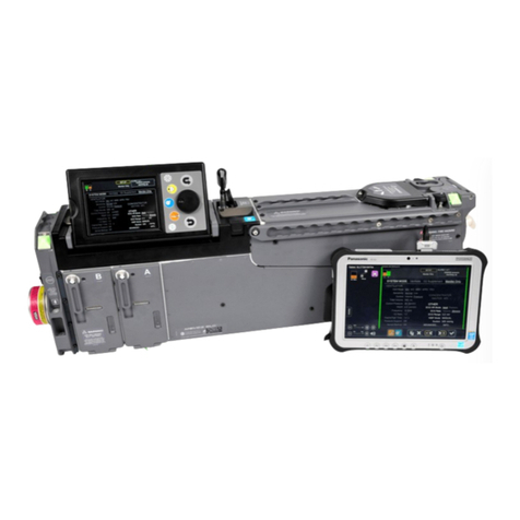
Thornhill Medical RESPIRACT RA-MR User manual

CAUTION:
•Investigational Device: Limited by Federal Law to Investigational Use Only
•Investigational Device: To Be Used by Qualified Investigators Only
•Instrument de Recherche : Réservé uniquement à l'usage de chercheurs
compétents
Operator’s Manual

Part Number: 127270 Rev. C 2020/MAR/25
© 2017 Thornhill Research Inc. All Rights Reserved

Thornhill Research Inc. RA-MR™ Operator’s Manual
iii
Contact Information
MANUFACTURER
Address: Thornhill Research Inc.
60 Wingold Ave
Toronto, Ontario
Canada M6B 1P5
Phone: +1.416.597.1325 or +1.888.597.1325
Website: www.thornhillmedical.com

Thornhill Research Inc. RA-MR™ Operator’s Manual
iv
Table of Contents
DEVICE INFORMATION.......................................................................................................................................................2
1. MANUFACTURER INFORMATION...........................................................................................................................2
2. SYSTEM INFORMATION.............................................................................................................................................2
2.1. SYSTEM’S INTENDED USE..........................................................................................................................................2
2.2. SYSTEM’S INTENDED OPERATOR...............................................................................................................................2
2.3. SYSTEM’S INTENDED OPERATING ENVIRONMENT.....................................................................................................2
2.4. SYSTEM’S INTENDED SUBJECT ..................................................................................................................................2
2.5. CONTRAINDICATIONS................................................................................................................................................2
3. OPERATING PROCEDURES .......................................................................................................................................3
3.1. GETTING STARTED ....................................................................................................................................................3
3.1.1. RA-MR™ CONTROL ROOM UNIT ....................................................................................................................5
3.1.2. The RA-MR™ MRI UNIT.....................................................................................................................................9
3.1.3. THE RA-MR™ SUBJECT BREATHING CIRCUIT AND CONSUMABLE MASK AND CIRCUIT ..................11
3.1.4. Initial Setup of the RA-MR™ System .................................................................................................................11
3.2. STARTING THE PROGRAM ........................................................................................................................................16
3.3. BUILD A STUDY .......................................................................................................................................................19
3.4. EDIT PARTICIPANTS.................................................................................................................................................26
3.5. CALIBRATE DEVICE.................................................................................................................................................27
3.6. SYSTEM INFO...........................................................................................................................................................34
3.7. DEPRESSURIZE.........................................................................................................................................................36
3.8. RUN ASESSION .......................................................................................................................................................36
3.8.1. Setting up a study...............................................................................................................................................36
3.9. MAIN USER SCREEN.................................................................................................................................................41
3.9.1. Navigating the Main Screen...............................................................................................................................41
3.10. BEGINNING A TEST..................................................................................................................................................43
3.10.1. Connecting the Subject to the System.................................................................................................................43
3.10.2. Run Prep............................................................................................................................................................48
3.10.3. Run Sequence.....................................................................................................................................................51
3.10.4. Shutdown System................................................................................................................................................51
3.11. TEST FILES ..............................................................................................................................................................52
3.11.1. EndTidal file ......................................................................................................................................................52
3.11.2. Events file...........................................................................................................................................................53
4WARNINGS AND PRECAUTIONS............................................................................................................................54
5SOFTWARE ALARMS & ERRORS...........................................................................................................................56
6SPECIFICATIONS........................................................................................................................................................60
6.1 OPERATING ENVIRONMENT.....................................................................................................................................60
6.2 STORAGE ENVIRONMENT ........................................................................................................................................60
6.3 PHYSICAL DIMENSIONS ...........................................................................................................................................60
6.4 INPUT POWER...........................................................................................................................................................60
6.5 RA-MR™ SPECIFICATIONS .....................................................................................................................................60
7SYSTEM SUPPLY LIST REQUIREMENTS .............................................................................................................61
8SERVICE AND MAINTENANACE SCHEDULE .....................................................................................................62
8.1 SYSTEM CLEANING..................................................................................................................................................62
9PACKING AND UNPACKING INSTRUCTIONS.....................................................................................................63
9.1 UNPACKING INSTRUCTIONS.....................................................................................................................................63
9.2 REPACKING INSTRUCTIONS .....................................................................................................................................66

Thornhill Research Inc. RA-MR™ Operator’s Manual
v
10 STAND AND OXYGEN RESERVOIR ASSEMBLY INSTRUCTIONS..................................................................69
10.1 STAND ASSEMBLY...................................................................................................................................................69
10.2 MOUNTING MRI UNIT ON STAND AND INSTALLING OXYGEN RESERVOIR.................................................................74
10.3 REMOVING MRI UNIT FROM STAND FOR SHIPPING FOR CALIBRATION AND MAINTENANCE......................................78

Thornhill Research Inc. RA-MR™ Operator’s Manual
2
DEVICE INFORMATION
Device Name: RA-MR™
Device Model: RA-MR
1. MANUFACTURER INFORMATION
Thornhill Research Incorporated
60 Wingold Avenue
Toronto, Ontario, Canada
M6B 1P5
2. SYSTEM INFORMATION
2.1.SYSTEM’S INTENDED USE
The intended use of the RA-MR™ system is to control end-tidal partial pressures of CO2& O2in
spontaneously breathing subjects.
2.2.SYSTEM’S INTENDED OPERATOR
RA-MRTM is intended to be used by trained persons under the supervision of a physician in
compliance with approved research or clinical protocols.
2.3.SYSTEM’S INTENDED OPERATING ENVIRONMENT
The RA-MR™ System is to be used in a research institution or laboratory environment, such as
MR suites, and hospital settings.
2.4.SYSTEM’S INTENDED SUBJECT
The RA-MR™ is intended to be used on spontaneously breathing subjects between 30kg and
100kg.
2.5.CONTRAINDICATIONS
The RA-MR™ is not intended to be used on subjects with any of the following conditions:
Absolute contraindications:
•Subjects refusing to undergo testing
•Subjects with obstructive or resistive lung disease whose PaCO2at rest is greater than
50mmHg or whose venous serum bicarbonate is greater than 26 mEq/L
•Subjects with pre-existing respiratory acidosis
•Subjects who require portable oxygen at rest or with exercise
•Subjects with chronic heart failure or severe pulmonary disease who are unable to
climb one flight of stairs due to shortness of breath
•Subjects with severe heart failure or restrictive lung disease with resting respiratory
rate over 15 breaths/min

Thornhill Research Inc. RA-MR™ Operator’s Manual
3
Relative contraindications:
•Pregnancy
•Obtundation
•Coma
•Confusion
•Delirium
•Dementia
•Unable to understand or carry out commands regarding keeping still and breathing
pattern
•Increased intracranial pressure due to space occupying lesion of obstruction of
outflow of CSF
•Intracerebral bleeding
•Subdural bleeding
•Cerebral edema
•Metabolic acidosis
3. OPERATING PROCEDURES
3.1.GETTING STARTED
The RA-MR™ system consists of 4 main components:
1. RA-MR™ Control Room Unit
2. RA-MR™ User Interface
3. RA-MR™MRI Unit
4. RA-MR™ Subject Breathing Circuit and RA-MR™ Consumable Mask and Circuit
(the system must be used only with RA-MR™ Consumable Masks and Circuits
supplied by Thornhill Research Inc. Non-specified accessories may impair the
performance).

Thornhill Research Inc. RA-MR™ Operator’s Manual
4
System Block Diagram

Thornhill Research Inc. RA-MR™ Operator’s Manual
5
3.1.1. RA-MR™ CONTROL ROOM UNIT
The FRONT PANEL of the RA-MR™ CONTROL ROOM UNIT is pictured below.
Windows A and B are shown in greater detail below.

Thornhill Research Inc. RA-MR™ Operator’s Manual
6
The function of each component is as follows:
1) Emergency Stop –Pressing this will ensure that the system is in a safe state, where the
subject breathes room air with no supply gases added. Once engaged, it must be reset
manually by rotating the button clockwise.
2) Alarm indicator light –Indicates the alarm state of the system. Refer to the user
interface MAIN SCREEN Notices to determine the cause of the error.
a) Solid Green –No alarm
b) Solid Yellow –Low priority alarm
c) Flashing Yellow –Medium priority alarm
d) Flashing Red –High priority alarm –the system is in a safe state where the
subject breathes room air with no CO2or hypoxic O2being added
3) Delivering –When illuminated blue, indicates when device is controlling gas delivery
during a sequence.

Thornhill Research Inc. RA-MR™ Operator’s Manual
7
The BACK PANEL of the RA-MR™ CONTROL ROOM UNIT is pictured below.

Thornhill Research Inc. RA-MR™ Operator’s Manual
8
The functions of each component are as follows:
4) Power switch –Turns control room unit power on or off.
NOTE: RA-MR™ USER INTERFACE has separate power switch.
5) Power cord adapter –Connect only the supplied medical grade power cord.
6) User Interface –Connects the control room unit to the RA-MR™ USER INTERFACE
to allow communication. The cable should be plugged into #6 above and into the
indicated port on the user interface computer prior to powering up the system.
7) Calibration Gas inlet (10% O2, 9% CO2, balance N2) –Connect to the calibration gas
supply at 40-60psi pressure.
8) Gas B inlet (10% O2, 90% CO2) –Connect to the gas cylinder supply at 40-60psi
pressure. Ensure:
a) The gas cylinder has sufficient gas supply to complete the study.
b) The gas cylinder is fully open to the regulator prior to connecting to the gas
inlet.
9) Gas C inlet (100% O2) –Connect to the O2gas supply line at 40-60psi pressure. If using
a gas cylinder as O2supply, ensure:
a) The gas cylinder has sufficient O2to complete the study, and
b) The gas cylinder is fully open to the regulator prior to connecting to gas inlet.
10) Gas A inlet (10% O2, 90% N2) –Connect to the gas cylinder supply at 40-60psi pressure.
Ensure:
a) The gas cylinder has sufficient gas supply to complete the study.
b) The gas cylinder is fully open to the regulator prior to connecting to gas inlet.
11) Black and Red Fiber Connections –Connect the matching fiber connections from the
RA-MR™ HOSE AND FIBER BUNDLE. These connections send data between the
RA-MR™ CONTROL ROOM UNIT and the RA-MR™ MRI UNIT.
Note: Always connect the gas lines of the RA-MR™ HOSE AND FIBER BUNDLE
before connecting the fiber lines. Similarly, disconnect the fiber lines before
disconnecting the gas lines. Failure to do so may result in fiber line damage.
12) CO2outlet (yellow) –Connect to appropriate gas line (yellow) in the RA-MR™ HOSE
AND FIBER BUNDLE.
Note: The RA-MR™ CONTROL ROOM UNIT must be turned off when connecting
or disconnecting this outlet.
13) Base gas outlet (blue)- Connect the appropriate gas line (blue) in the RA-MR™ HOSE
AND FIBER BUNDLE.
14) O2outlet (green)- Connect the appropriate gas line (green) in the RA-MR™ HOSE AND
FIBER BUNDLE.
Note: The RA-MR™ CONTROL ROOM UNIT must be turned off when connecting
or disconnecting this outlet.

Thornhill Research Inc. RA-MR™ Operator’s Manual
9
3.1.2. The RA-MR™ MRI UNIT
The FRONT PANEL of the RA-MR™MRI UNIT is pictured below.
The function of each component is as follows:
1) CO2gas outlet –Connects the appropriate gas line (yellow) from the mask hosing.
2) Breathing hose- Connects the appropriate line from the mask hosing.
3) O2outlet- Connects the appropriate gas line (green) from the mask hosing.
4) Pressure sensor inlet –Attach the mouth pressure sampling line from the mask hosing.
5) Gas sample port- Attach the gas sample line from the mask hosing.

Thornhill Research Inc. RA-MR™ Operator’s Manual
10
The BACK PANEL of the RA-MR™MRI UNIT is pictured below.
The functions of each component are as follows:
6) Gas C inlet (100% O2) –Connect the appropriate gas line (Green) in the RA-MR™ HOSE
AND FIBER BUNDLE. Provides oxygen delivery from the RA-MR™ CONTROL ROOM
UNIT to the RA-MR™ MRI UNIT.
Note: The RA-MR™ CONTROL ROOM UNIT must be turned off when connecting or
disconnecting this inlet.
7) Black and red fiber connection- Connect the matching color fiber connection from the RA-
MR™ HOSE AND FIBER BUNDLE.
Note: Always connect the gas lines of the RA-MR™ HOSE AND FIBER BUNDLE before
connecting the fiber lines. Similarly, disconnect the fiber lines before disconnecting the gas
lines. Failure to do so may result in fiber line damage.
8) CO2inlet (10% O2, 90% CO2) –Connect the appropriate gas line (yellow) in the RA-MR™
HOSE AND FIBER BUNDLE.
Note: The RA-MR™ CONTROL ROOM UNIT must be turned off when connecting or
disconnecting this outlet.
9) Base Gas inlet (10% O2, 90% N2) –Connect the appropriate gas line in the RA-MR™ HOSE
AND FIBER BUNDLE (Blue).
IMPORTANT: It is recommended to connect this gas line first when connecting the RA-MR™
HOSE AND FIBER BUNDLE. This ensures the easiest connection of the bundle. Connect the
fiber lines last. When disconnecting, remove the fiber connections first to prevent damage to the
cables.

Thornhill Research Inc. RA-MR™ Operator’s Manual
11
3.1.3. THE RA-MR™ SUBJECT BREATHING CIRCUIT AND CONSUMABLE MASK AND
CIRCUIT
•Use the RA-MR™ System only with a disposable breathing mask manifold supplied by
Thornhill Research Inc.
•Connect the RA-MR™ SUBJECT BREATHING CIRCUIT to the RA-MR™Control
ROOM UNIT and to the RA-MR™ CONSUMABLE MASK AND CIRCUIT as outlined
in the sections below.
3.1.4. Initial Setup of the RA-MR™ System
NOTE: THE RA-MR™ USER INTERFACE, RA-MR™ CONTROL ROOM UNIT
AND GAS TANKS ARE NOT MR SAFE AND SHOULD NEVER BE BROUGHT INTO
THE MR ROOM.
•First, connect the following:
1. The computer connection from the back of the RA-MR™ USER INTERFACE COM 1
port to the cable port on the rear panel of the RA-MR™ CONTROL ROOM UNIT.
2. The RA-MR™ USER INTERFACE power supply to an AC power outlet.
Note: To access the COM 1 port and the power supply connection port on the back of the
RA-MR™ USER INTERFACE, the rear cable cover must be removed by loosening the
associated three screws. Although the computer can be operated fully through the touch
interface, the supplied mouse and/or keypad can also be connected at the time. Once the
cables are in place, the cables can be routed through the middle opening and the cover
reattached.
3. The RA-MR™ CONTROL ROOM UNIT power supply to an AC power outlet, and to
the power connector on the rear panel.
4. Ensure the RA-MR™ HOSE AND FIBER BUNDLE is fed through stand holder on the
RA-MR™ MRI UNIT. Failure to do so may cause tipping hazard.
WARNING: DO NOT CONNECT THE COMPUTER TO A NETWORK CABLE OR
ANY OTHER DEVICES THAT WERE NOT SUPPLIED WITH THIS SYSTEM.
`

Thornhill Research Inc. RA-MR™ Operator’s Manual
12
5. Connect the RA-MR™ HOSE AND FIBER BUNDLE to the rear panel of the control
room unit and to the rear of RA-MR™ MRI UNIT. The end of the RA-MR™ HOSE
AND FIBER BUNDLE that attaches to the RA-MR™ CONTROL ROOM UNIT has a
red band with the following label:

Thornhill Research Inc. RA-MR™ Operator’s Manual
13
•When connecting the RA-MR™ HOSE AND FIBER BUNDLE to the RA-
MR™MRI UNIT, always start with the base gas line first (the center blue
line). Continue with the yellow and green gas lines.
•Next connect the two fiber lines, ensuring that the colors match.

Thornhill Research Inc. RA-MR™ Operator’s Manual
14
•To connect the RA-MR™ HOSE AND FIBER BUNDLE gas lines to the rear
panel of the RA-MR™ MRI UNIT, first depress the tab on the connector as
shown in the following picture then insert the gas line into place (to remove the
connection, depress the tab).
6. Place RA-MR™ MRI UNIT in appropriate position in MR room. Note: RA-MR™
MRI UNIT can operate in magnetic fields up to 500 Gauss. If placed too close to magnet, it
will first cause the gas sample pump to fail, then the power supply. The alarm indicator light
found on RA-MR™ MRI UNIT should be green or yellow, if light begins blinking red or
no lights are present then unit is too close to magnet. Simply moving unit a few centimeters
further from the magnet will restart failed functions.
7. Connect the gas lines from the tanks or wall supplies to the respective connections on the
rear panel of the RA-MR™ CONTROL ROOM UNIT.
a) Turn on the gas cylinder regulators and ensure there is a sufficient supply
(tank pressure) to complete the study. Note: 500 PSI signifies an empty tank.
b) Connect the colour-coded input hoses to the corresponding gas inlets. Note
that the connectors are keyed and may require rotation of up to 90 degrees
before they align with the inlet connector (To remove the connector, pull the
connector by the outer most collar).

Thornhill Research Inc. RA-MR™ Operator’s Manual
15
8. Connect lines from the RA-MR™ SUBEJCT BREATHING CIRCUIT to front of
RA-MR™ MRI UNIT and to RA-MR™ CONSUMABLE MASK AND CIRCUIT
(see picture below):
NOTE: THE MASK MUST NOT BE ON THE SUBJECT’S FACE AT THIS POINT.
9. Turn on the RA-MR™ USER INTERFACE via the power button.
10. Turn on the RA-MR™ CONTROL ROOM UNIT by pressing the power button.

Thornhill Research Inc. RA-MR™ Operator’s Manual
16
3.2.STARTING THE PROGRAM
The RA-MR™ System program will automatically start once the RA-MR™ User Interface
is turned on. However, if the program was previously exited (such as exiting to perform data
and file management), the program may be re-accessed by double-click the ‘RA-MR™
System User Icon’on the desktop.
This will bring up the following Main User Startup Screen:
If there is no communication between the RA-MR™ CONTROL ROOM UNIT and the RA-MR™
USER INTERFACE, the ‘Start Session’and ‘Calibrate Device’options will be greyed out. Make
sure RA-MR™ CONTROL ROOM UNIT is turned on and connected to the RA-MR™ USER
INTERFACE.
Table of contents
Other Thornhill Medical Medical Equipment manuals
Popular Medical Equipment manuals by other brands

Atos Medical
Atos Medical TheraBite JAW MOTION REHABILITATION SYSTEM Instructions for use

Bears of Hope
Bears of Hope Cuddle Cots Package and Assembly

Galvin Engineering
Galvin Engineering ClevaCare CLEVA010 Installation guidelines

ECOPOSTURAL
ECOPOSTURAL C3523 instructions

Petermann
Petermann Pegasus manual

Wonjin Muslan
Wonjin Muslan POWER-Q6000II user manual