Thrane&Thrane SAILOR 500 FleetBroadband User manual

SAILOR
500/250 FleetBroadband
USER MANUAL
BUY NOW

Thrane & Thrane A/S
SAILOR®500 FleetBroadband
SAILOR®250 FleetBroadband
User manual
Document number: TT98-125645-C
Release date: December 12, 2007

Information in this document is subject to change without notice and does not represent
a commitment on the part of Thrane & Thrane A/S. We recommend downloading the
latest version of the manual from the Thrane & Thrane Extranet.
Copyright © 2007 Thrane & Thrane A/S. All rights reserved.
Trademark acknowledgements:
•Thrane & Thrane is a registered trademark of Thrane & Thrane A/S in the European
Union and the United States.
•SAILOR is a registered trademark of Thrane & Thrane A/S in the European Union, the
United States and other countries.
•Windows and Outlook are registered trademarks of Microsoft Corporation in the
United States and other countries.
•Inmarsat is a registered trademark of International Maritime Satellite Organisation
(IMSO) and is licensed by IMSO to Inmarsat Limited and Inmarsat Ventures plc.
• Inmarsat’s product names are trademarks or registered trademarks of Inmarsat.
• Other product and company names mentioned in this manual may be trademarks or
trade names of their respective owners.

iii
Safety summary 1
The following general safety precautions must be observed during all
phases of operation, service and repair of this equipment. Failure to comply
with these precautions or with specific warnings elsewhere in this manual
violates safety standards of design, manufacture and intended use of the
equipment. Thrane & Thrane A/S assumes no liability for the customer's
failure to comply with these requirements.
Observe marked areas
Under extreme heat conditions do not touch
areas of the terminal or antenna that are
marked with this symbol, as it may result in
injury.
Microwave radiation hazards
During transmission the antenna in this system radiates Microwave
Power.This radiation may be hazardous to humans close to the antenna.
During transmission, make sure that nobody gets closer than the
recommended minimum safety distance.
On the SAILOR 500 FleetBroadband, the
minimum safety distance on the focal line to
the antenna panel is 1.3 m, based on a
radiation level of 10 W/m2. The radiation level is
100 W/m2at a distance of 0.4 m from the
antenna panel. Refer to the drawing on the
next page.
On the SAILOR 250 FleetBroadband, the
minimum safety distance on the focal line to
the antenna panel is 0.6 m, based on a
radiation level of 10 W/m2. The radiation level is
100 W/m2at a distance of 0.2 m from the
antenna panel. Refer to the drawing on the
next page.

iv
Distance to other equipment
Do not move the antenna closer to radars than the minimum safe distance
specified in the installation manual - it may cause damage to the antenna.
The equipment must be installed with the following minimum safe distances
to magnetic steering compass:
SAILOR FleetBroadband terminal: min. 0.3 m.
SAILOR 500 FleetBroadband antenna: min. 1.0 m
SAILOR 250 FleetBroadband antenna: min. 1.1 m
Service
User access to the interior of the terminal is prohibited. Only a technician
authorized by Thrane & Thrane A/S may perform service - failure to comply
with this rule will void the warranty. Access to the interior of the antenna is
allowed, but only for replacement of certain modules - as described in the
Installation manual. General service may only be performed by a technician
authorized by Thrane & Thrane A/S.
Do not service or adjust alone
Do not attempt internal service or adjustments unless another person,
capable of rendering first aid resuscitation, is present.
SAILOR 500:
MICROWAVE RADIATION
No personnel within safety distance
25°for SAILOR 500
60°for SAILOR 250
Safety distance:
(0.4 m, 100 W/m2)
1.3 m, 10 W/m2
SAILOR 250:
(0.2 m, 100 W/m2)
0.6 m, 10 W/m2

v
Grounding, cables and connections
To minimize shock hazard, the equipment chassis and cabinet must be
connected to an electrical ground. Both terminal and antenna must be
grounded to the ship. For further grounding information refer to the
Installation manual.
Do not extend the cables beyond the lengths specified for the equipment.
The cable between the terminal and antenna can be extended if it complies
with the specified data concerning cable losses etc.
All cables for the SAILOR FleetBroadband system are shielded and should
not be affected by magnetic fields. However, try to avoid running cables
parallel to AC wiring as it might cause malfunction of the equipment.
Power supply
The voltage range is 10.5 - 32 V DC; 14 A - 5.5 A. It is recommended that the
voltage is provided by the 24 V DC power bus on the ship. Be aware of high
start-up peak current: 20 A@24 V, 5 ms.
If a 24 V DC power bus is not available, an external 115/230 VAC to 24 V DC
power supply can be used.
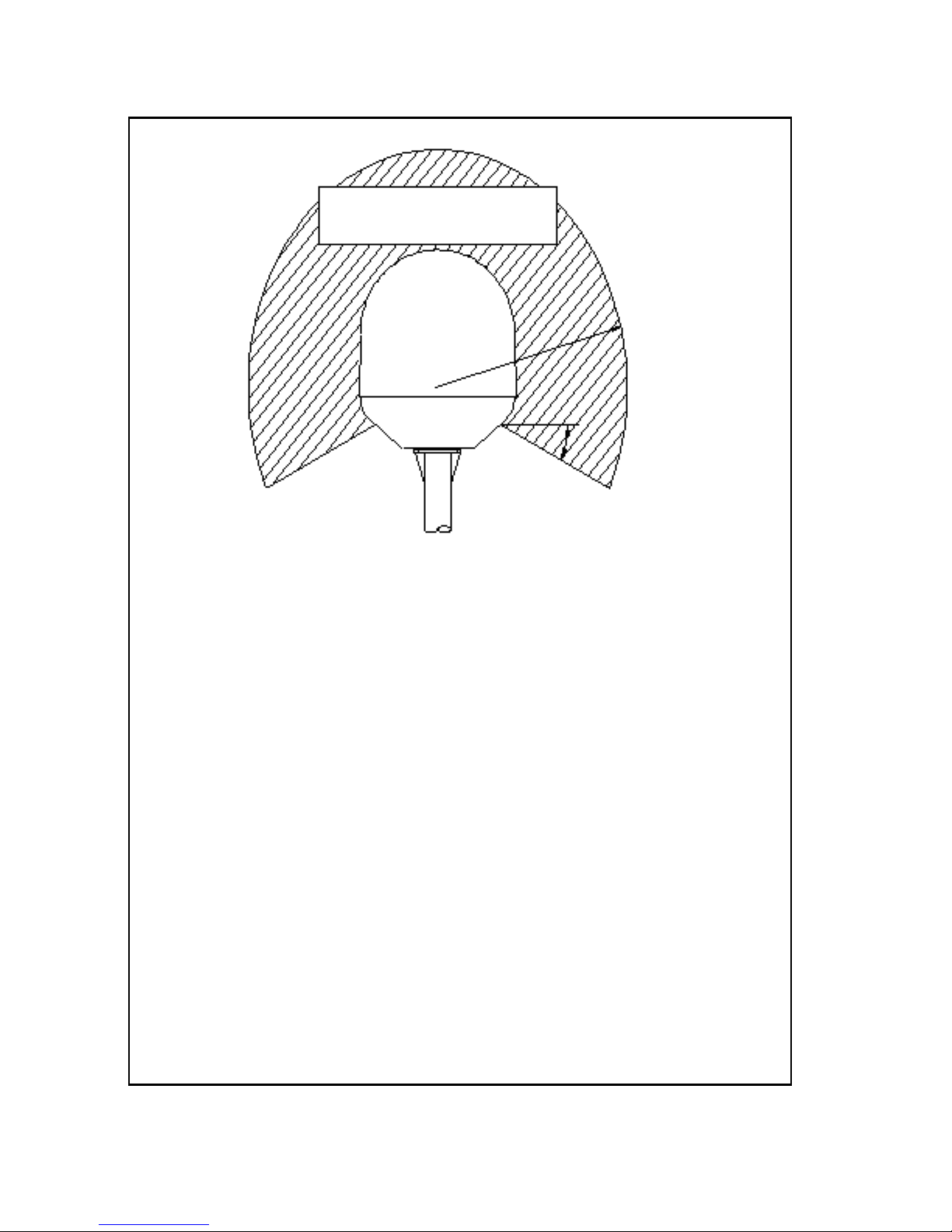
Equipment ventilation
To ensure adequate cooling of the terminal, 5 cm of unobstructed space
must be maintained around all sides of the unit (except the bottom side).
The ambient temperature range of the terminal is: -25°to +55°C.
Do not operate in an explosive atmosphere
Do not operate the equipment in the presence of flammable gases or fumes.
Operation of any electrical equipment in such an environment constitutes a
definite safety hazard.
Keep away from live circuits
Operating personnel must not remove equipment covers. Component
replacement and internal adjustment must be made by qualified
maintenance personnel. Do not replace components with the power cable
connected. Under certain conditions, dangerous voltages may exist even
with the power cable removed. To avoid injuries, always disconnect power
and discharge circuits before touching them.
Failure to comply with the rules above will void the warranty!

vi
Mandatory safety instructions to installers &
users of SAILOR®250 FleetBroadband 2
Use only manufacturer or dealer supplied antenna.
Antenna minimum safe distance: 0.415 m.
Antenna gain 12.2 dBi referenced to isotropic.
The Federal Communications Commission has adopted a safety
standard for human exposure to RF (Radio Frequency) energy,
which is below the OSHA (Occupational Safety and Health Act)
limits.
Antenna mounting
The antenna supplied by the manufacturer or radio dealer must
not be mounted at a location such that during radio transmission,
any person or persons can come closer than the above indicated
minimum safe distance to the antenna i.e. 0.415 m.
To comply with current FCC RF Exposure limits, the antenna must
be installed at or exceeding the minimum safe distance shown
above, and in accordance with the requirements of the antenna
manufacturer or supplier.
Base Station Installation: The antenna should be fixed-mounted
on an outdoor permanent structure. RF Exposure compliance must
be addressed at the time of installation.
Antenna substitution
Do not substitute any antenna for the one supplied or
recommended by the manufacturer or radio dealer. You may be
exposing person or persons to excess radio frequency radiation.
You may contact your radio dealer or the manufacturer for further
instructions.

vii
Warning
Maintain a separation distance from the antenna to a person(s) of
at least 0.415 m.
You, as the qualified end-user of this radio device must control the
exposure conditions of bystanders to ensure the minimum
separation distance (above) is maintained between the antenna
and nearby persons for satisfying RF Exposure compliance. The
operation of this transmitter must satisfy the requirements of
Occupational/Controlled Exposure Environment, for work-related
use. Transmit only when person(s) are at least the minimum
distance from the properly installed, externally mounted antenna.
Note Thrane & Thrane recommends a minimum safety
distance of 0.6 m to the SAILOR 250 FleetBroadband
antenna.

viii
About the manual 3
Intended readers
This manual is a user manual for the SAILOR 500 FleetBroadband
system and the SAILOR 250 FleetBroadband system. The readers of
the manual include anyone who is using or intends to use one of
these two systems. No specific skills are required to operate the
SAILOR FleetBroadband system. However, it is important that you
observe all safety requirements listed in the beginning of this
manual, and operate the system according to the guidelines in this
manual.
Manual overview
Note that this manual does not cover installation nor does it cover
how to use the IP handset that comes with the system. For
information on installation refer to the installation manual and for
information on the IP handset refer to the user manual for the IP
handset. Part numbers for both manuals are listed in the next
section.
This manual has the following chapters:
•Introduction contains an overview of the BGAN services and a
brief description of the system.
•Getting started explains how to insert SIM card and start up the
unit. It also contains a short guide to making the first call.
•Operating the system explains how to use the system.
•Using the web interface explains how to use the built-in web
interface of the terminal, and describes the available menus
and settings, including advanced setup of interfaces.
•Troubleshooting contains a short troubleshooting guide and
explains how to update software. It also describes the functions
of the light indicators and the Reset button, and gives
information on where to get further help if needed.

ix
This manual may not always reflect the latest software
functionality of your terminal. To obtain the latest version of the
manual, please enter the Thrane & Thrane Extranet and download
the latest version, or acquire it from your distributor.
Related documents
The below list shows the documents related to this manual and to
the SAILOR 500 FleetBroadband and SAILOR 250 FleetBroadband
systems.
Title and description Document
number
SAILOR 500 FleetBroadband
SAILOR 250 FleetBroadband
Installation Manual
Explains how to install the
SAILOR FleetBroadband terminal, the
SAILOR 500 FleetBroadband antenna and the
SAILOR 250 FleetBroadband antenna.
TT 98-125646
SAILOR 500/250 FleetBroadband, Quick Guide
A short guide to the most important functions
of the SAILOR FleetBroadband systems.
TT98-125647
Thrane & Thrane IP Handset, User Manual
Explains the features and functions of the
Thrane & Thrane IP handset. The IP handset
works as a standard IP handset, but also serves
as a user interface for the
SAILOR FleetBroadband systems.
TT98-126059

x
Typography
In this manual, typography is used as indicated below:
Bold is used for the following purposes:
• To emphasize words.
Example: “Do not touch the antenna”.
• To indicate what the user should select in the user interface.
Example: “Select SETTINGS > LAN”.
Italic is used to emphasize the paragraph title in cross-references.
Example: “For further information, see Connecting Cables on
page...”.
COURIER is used to indicate low level commands such as AT
commands.
Example: “In your terminal program, type ATD”.

xi
Table of Contents
Safety summary ................................................................iii
Mandatory safety instructions to installers & users of
SAILOR®250 FleetBroadband ............................................vi
About the manual ............................................................ viii
Chapter 1 Introduction
Welcome ............................................................................ 1
In this chapter ....................................................................2
Features and interfaces ......................................................3
Main units ..........................................................................4
SAILOR®500 FleetBroadband/ SAILOR®250 FleetBroadband ......4
Units overview ......................................................................4
SAILOR FleetBroadband antennas ...........................................5
SAILOR FleetBroadband terminal ............................................7
IP handset and cradle ...........................................................9
The Inmarsat BGAN system ............................................... 11
What is BGAN? .................................................................... 11
The Inmarsat FleetBroadband service ..................................... 11
Coverage ............................................................................12
Overview of the FleetBroadband system ..................................13
The BGAN services ...............................................................14
Matrix of services and interfaces ......................................17
What’s next? .................................................................... 18
Chapter 2 Getting started
In this chapter ...................................................................19

Table of Contents
xii
Getting started with the terminal ..................................... 19
Operation at high temperatures ............................................ 19
Connector panel ................................................................ 20
Starting up the terminal ...................................................... 20
Connecting the IP handset ................................................22
Power supply ......................................................................22
Starting up the IP handset ....................................................22
Making the first data connection (LAN) .............................23
Before connecting to the LAN interface ..................................23
Connecting a computer to the LAN interface ...........................23
Entering the SIM PIN for the terminal ...............................24
Overview ............................................................................24
Entering the PIN using a phone or IP handset ........................24
Entering the PIN using the web interface ...............................26
Connecting to the BGAN network ......................................27
Making the first call .........................................................29
Introduction .......................................................................29
Making a call from the terminal ............................................29
Making a call to the terminal ................................................29
Making a call from one terminal to another ........................... 30
What’s next? ................................................................... 30
Chapter 3 Operating the system
In this chapter .................................................................. 31
General ............................................................................ 31
Tools for setup and use ........................................................ 31
Services and interfaces ........................................................33

Table of Contents
xiii
Using a phone or fax machine ..........................................34
Available interfaces .............................................................34
Selecting the call type .........................................................35
Making or receiving a phone call ..........................................38
Making a call to the terminal ................................................40
Dialing functions .................................................................41
Sending or receiving a fax message ......................................46
Using a computer .............................................................48
Available interfaces .............................................................48
Standard or Streaming data on LAN ......................................48
Working with network groups ..............................................50
Using the IP handset .........................................................51
What’s next? .....................................................................51
Chapter 4 Using the web interface
In this chapter ..................................................................53
Introduction .....................................................................53
The web interface ...............................................................53
Accessing and navigating the web interface ...........................55
Entering the SIM PIN in the web interface ........................58
The Dashboard .................................................................59
Overview ...........................................................................59
Properties ..........................................................................60
Managing data sessions .......................................................61
Using the phone book ......................................................65
General usage ....................................................................65
Editing phone book entries ..................................................68
Viewing and editing the mobile numbers ...............................69
Using the Call log .............................................................70
Information on total usage ...................................................70
Exporting the call log ...........................................................71
Viewing the lists of calls ......................................................72

Table of Contents
xiv
Handling messages ..........................................................73
Sending an SMS message ....................................................73
Options for messages in the Outbox .......................................74
Options for messages in the Sent folder .................................75
Sending an SMS message to the terminal ..............................75
Receiving a message ...........................................................76
Options for new SMS messages ............................................77
Options for SMS messages in the Inbox ..................................77
Configuring message settings ...............................................78
Setting up the interfaces .................................................. 80
The SETTINGS page (Antenna properties) .............................. 80
Enabling or disabling the L-Band interface ............................ 80
Configuring the LAN interface ............................................... 81
Configuring the Phone/Fax interface .................................... 85
Configuring the ISDN interface .............................................87
Setting the common interface settings .................................. 90
Setting up call services ........................................................92
Managing LAN network users ......................................... 99
Overview ........................................................................... 99
Setting up the network user groups ..................................... 100
Managing network devices ................................................. 104
The Network classification table .......................................... 106
Definitions for network terms .............................................. 109
Software upload and event log .........................................111
Uploading software .............................................................111
Viewing the Event list or the Event log .................................. 114
Selecting the preferred BGAN satellite ............................. 116
Administration ................................................................ 118
Accessing the administration settings ................................... 118
Call charges ......................................................................122
Log handling .....................................................................123
Using profiles ....................................................................124
Using traffic flow filters ...................................................... 128
Setting up user permissions ................................................ 131

Table of Contents
xv
Help desk and diagnostic report ......................................133
Accessing the Help desk .....................................................133
Generating a diagnostic report ............................................134
What’s next? ...................................................................134
Chapter 5 Troubleshooting
In this chapter .................................................................135
Getting support ...............................................................135
Overview ..........................................................................135
Airtime support .................................................................135
System support ..................................................................135
Uploading software .........................................................136
Viewing software version status ...........................................136
Uploading software using the web interface ..........................136
Spare parts, SAILOR®500 FleetBroadband ......................137
Antenna spare parts ...........................................................137
Cables ..............................................................................137
Spare parts, SAILOR®250 FleetBroadband ......................138
Cables ..............................................................................138
Options and accessories ..................................................139
Troubleshooting guide ....................................................140
Status signaling ..............................................................146
Overview ..........................................................................146
Light indicators .................................................................146
Event messages .................................................................150
Logging of events ............................................................ 151
Diagnostic report ............................................................... 151
Event log .......................................................................... 151
Reset button ....................................................................152
How to access the Reset button ...........................................152
Function of the Reset button ...............................................153

Table of Contents
xvi
Chapter 6 Conformity
SAILOR®500 FleetBroadband ......................................... 155
CE (R&TTE) ....................................................................... 155
SAILOR®250 FleetBroadband ...........................................157
CE (R&TTE) ........................................................................157
FCC ..................................................................................157
Glossary ....................................................................................... 159
Index ....................................................................................... 163

1
Chapter 1
1111
Introduction
Introduction 1
Welcome
Congratulations on the purchase of your SAILOR FleetBroadband system!
SAILOR 500 FleetBroadband and SAILOR 250 FleetBroadband are maritime
broadband systems, providing simultaneous high-speed data and voice
communication via satellite through the Broadband Global Area Network
(BGAN).

Chapter 1: Introduction
2 In this chapter
Applications include:
• Internet browsing
•E-mail
• Phone and fax services
• Large file transfers
• Video conferencing and Streaming
• VPN (Virtual Private Network) access to corporate servers
In this chapter
This chapter introduces the SAILOR 500 FleetBroadband system and the
SAILOR 250 FleetBroadband system, and gives an overview of the physical
units and their features and functions.
It also gives an overview of the BGAN system and services.

Chapter 1: Introduction
Features and interfaces 3
1111
Introduction
Features and interfaces
The SAILOR FleetBroadband system offers the following features and
interfaces:
Simultaneous voice and data communication over BGAN
Full duplex, single or multi-user, up to:
SAILOR 500 FleetBroadband: 432 kbps
SAILOR 250 FleetBroadband: 284 kbps
Support for streaming IP at:
SAILOR 500 FleetBroadband:32, 64, 128, 256 kbps
SAILOR 250 FleetBroadband: 32, 64, 128 kbps
ISDN service, only SAILOR 500 FleetBroadband:64 kbps
Voice: Standard Voice (4.0 kbps) or 3.1 kHz Audio
4 LAN ports with Power over Ethernet (PoE) for computers, e-hubs, IP
handsets etc.
2 Standard Phone/Fax ports for standard phones, fax machines or analog
modems
1 Euro ISDN port for ISDN phones or, for SAILOR 500 FleetBroadband only:
G4 fax or ISDN modem
1 L-Band output for connecting a broadcast receiver for maritime data
1 multi-purpose I/O connector with 5 configurable inputs/outputs
1 SIM slot for your BGAN SIM card
Integral DHCP/NAT router
Built-in web interface allowing you to manage your phone book,
messages and calls, and customize the terminal to your specific needs
Input power: 10.5 - 32 V DC (14 A - 5.5 A)
CE certified
Other manuals for SAILOR 500 FleetBroadband
2
This manual suits for next models
2
Table of contents
Other Thrane&Thrane Boating Equipment manuals
Popular Boating Equipment manuals by other brands

SLEIPNER MOTOR AS
SLEIPNER MOTOR AS PS600 Installation and user manual

Hobie
Hobie Mirage Drive Assembling

bamar
bamar MEJ 4.02 Use and maintenance instruction manual

VariProp
VariProp DF-80 Assembly and operating instructions

Wynn Marine
Wynn Marine 1850 EXTERNAL Series Installation and maintenance instructions

Quick
Quick MC2 X19 Installation and use manual