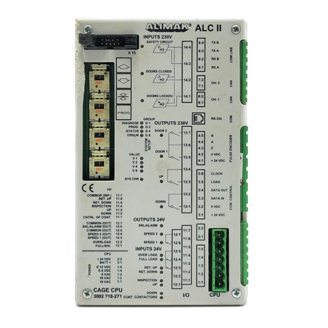
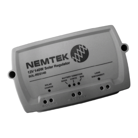
Thunder TDR15008 User manual

1
For your personal safety read, understand and
follow the information provided in this instruction
manual and on the solar regulator.
CONGRATULATIONS ON
YOUR PURCHASE OF YOUR
THUNDER SOLAR REGULATOR!

2
SPECIFICATIONS
Table of Contents
RATED CURRENT 30A OPERATING TEMPERATURE -10°C to 60°C
RATED VOLTAGE 12V/24V STORAGE TEMPERATURE -30°C to 70°C
OPEN CIRCUIT OF SOLAR PANEL <50V DIMENSIONS 90mm(L) x 188mm(W) x 48mm(D)
LOW VOLTAGE DISCONNECTION (LVD) 10.7V/21.4V MOUNTING HOLE SPACING 60mm x 178mm
FLOAT VOLTAGE 14V/28V WEIGHT 360g
LOW VOLTAGE RECONNECTION (LVR) 12.6V/25.2V BATTERY TYPE Wet cell rechargeable only
NO LOAD CURRENT ≤ 30ma

3
INSTALLATION
Installaion and Operation
1. Ensure the regulator is mounted as close to the battery as possible.
2. For best results use at least 6mm² automotive cable.
3. Connect the battery positive terminal (B+) and the battery negative terminal (B-) beneath the appropriate + and - symbols in the middle of the regulator.
Then connect the solar panel positive and negative leads beneath the appropriate + and - symbols at the left of the regulator. The + and - connectors
can be used to power a device directly off the regulator (not recommended for sensitive electronics).
4. Plug the external temperature sensor into the socket in the top left corner of the regulator. The temperature sensor is required for temp compensation on
the high voltage disconnect function.
SOLAR PANEL DC LOAD
BATTERY

4Components
DESCRIPTION OF LCD SYMBOLS
LCD SYMBOLS
Load circuit off No charge going to battery
Load circuit on (no current) Bulk charging battery
Load circuit on (current being drawn) Float charging battery
System is working correctly Battery running low
Battery capacity indicator Solar power active
Solar not active Load timer control on

5
Specifications
VIEW AND PROGRAM SETTINGS
The regulator will default to the “battery voltage” screen after correct installation to battery. Use the menu button to switch view to desired screen.
Press the menu button to cycle from on view to the next.
Battery Voltage
Displays current battery voltage, charge status, discharge status and
battery capacity. In this screen, press and hold the menu button
(>5 seconds) to shut off the load circuit.
Environment Temperature
Displays current temperature, charge status, discharge status and battery
capacity.
Solar Panel Charge Current
Displays the charging current from the solar panel and battery capacity.
Load Discharge Current
Displays the discharge current and battery capacity.
Accumulated Charge (Ah)
Displays the total amount of charge received from the solar panel in amp
hours since connection/last reset. To reset to 0, press and hold the menu
button (>5 seconds).

6
Accumulated Discharge (Ah)
Displays the total amount of discharge, in amp hours, from the regulators
load circuit since connection/last reset. To reset to 0, press and hold the
menu button (>5 seconds).
Low Voltage Disconnect
Displays the value for the low voltage disconnection (LVD). Once the
battery voltage gets to this level the load circuit will be shut off and show
the second screen above. To adjust the LVD voltage, press and hold the
menu button (>5 seconds), once the numbers start flashing, use the arrow
buttons to change the voltage. To save the settings and return to normal
view, press and hold the menu button (>5 seconds).
Low Voltage Reconnect
Displays the value for the low voltage reconnection (LVR). Once the battery
voltage gets to this level the load circuit will turn back on. To adjust the LVR
voltage, press and hold the menu button (>5 seconds), once the numbers
start flashing, use the arrow buttons to change the voltage. To save the
settings and return to normal view, press and hold the menu button
(>5 seconds).
High Voltage Disconnect
Displays the value for the high voltage disconnection (HVD). Once the battery
voltage gets to this level the regulator will cut off the charging circuit to the
battery to prevent overcharging of the battery. Once the battery voltage drops
below this level, the circuit will be re-connected. To adjust the HVD voltage,
press and hold the menu button (>5 seconds), once the numbers start
flashing, use the arrow buttons to change the voltage. To save the settings
and return to normal view, press and hold the menu button (>5 seconds).
Installation and Connection
VIEW AND PROGRAM SETTINGS
Ah

7
Safety Precautions
VIEW AND PROGRAM SETTINGS
Load Delay
Display shows the delay time for load disconnect. To adjust the load delay,
press and hold the menu button (>5 seconds), once the numbers start
flashing, use the arrow buttons to change the voltage. To save the settings
and return to normal view, press and hold the menu button (>5 seconds).
The delay can be set in increments of 1 hour from 0 - 24hrs. If set to 24h,
the load circuit will remain on at all times, provided there are no faults
detected. If set 1 - 23h, the load circuit will remain on that many hours after
solar input cuts out. If set to 0h, the load circuit will only be active without
solar input.
Common Fault Codes and Handling
Overload: The screen will display as shown, meaning that over 30A is
trying to be drawn from the load circuit. To remedy, reduce the load, press
the menu button then press the down arrow to restore power to the circuit.
Short Circuit
The screen will display as shown. To remedy, check all cables and remove
the short, press the menu button then press the down arrow to restore
power to the circuit.

This manual suits for next models
1
Table of contents
