Smartrise C4 User manual


C4 User Manual
October 25, 2021 ©2021 Smartrise Engineering, Inc. All Rights Reserved Page i
Document History
Date
Version
Summary of Changes
October 25, 2021
4.1
Added 24 Input Board
Removed Manual Traction Test
September 30, 2021
4.0
Added Advanced Configuration
Added Hoistway Access Slide Distance
Added Hall Call Security
Moved all Car Data information to one section
Added I/O definitions
Added Input Status
Updated Access Code
Added description for Floor Adjustment menu
Added Invert Outputs
Added Recall Key
Deleted Sabbath Dwell Timer menu
Moved Sabbath Operation to SETUP menu
Added VIP
Added Active Shooter
Added Marshal Mode
Replaced brackets used on Sensor Array Assembly.
Added Swing Opening
Added an Enter Door Command display when there is only
front doors configured
Added Door Type
Added Brakes
November 13, 2020
3.1
Added Emcan LWD reference and Hall board 12 DIP Hall
Mask Mapping switch settings
October 30, 2020
3.0
Deleted Load Weighing section and created a reference to
the C4 Load Weighing manual
Deleted DAD connection procedure and created a
reference to the C4 GUI manual
Replaced Emergency section
Updated all menu structures
Replaced CT and COP figures due to jumper
Replaced S-Curve drawing with a more detailed drawing
Added a 12-DIP configuration Hall board
Added and deleted menu functions
Added reference to specific drive when wiring C4 for
Construction Mode
Added Debug, About, Status, XREG, Attendant, Parking
sections
Expanded Doors, Faults, Alarms, Floors, S-Curve, and Speed
sections to include additional menu descriptions and
procedures

C4 User Manual
Page ii ©2021 Smartrise Engineering, Inc. All Rights Reserved October 25, 2021
Date
Version
Summary of Changes
August 15, 2019
2.0
Updated cover page
Added Menu Structures
Added Soft Limit
Added Sabbath Operation
Added Load Weighing
Added Alarms
Added In-depth process descriptions
Added NTS/ETS
Added Profile, Parameters and Controlling Initial Start of
Car Motion information to S-Curve
Deleted Faults table and added reference to see C4 Faults
and Alarms document
March 28, 2019
1.0
Initial Submittal

C4 User Manual
October 25, 2021 ©2021 Smartrise Engineering, Inc. All Rights Reserved Page iii
Table of Contents
1C4 Traction Controller....................................................................................1
1.1 Overview.......................................................................................................................1
1.2 C4 Traction Controller Components...............................................................................2
1.3 Safety............................................................................................................................5
1.4 Default Voltage Settings Prior to Installation..................................................................5
2Controller Hardware ......................................................................................6
2.1 MR Board SR3032..........................................................................................................7
2.1.1 Navigation Buttons.........................................................................................................9
2.1.2 24 VDC Power Source ..................................................................................................10
2.1.3 Reset Buttons ...............................................................................................................10
2.1.4 Drive Communication ..................................................................................................11
2.1.5 Network ........................................................................................................................11
2.1.6 120 VAC Inputs and Outputs (Factory) .......................................................................13
2.1.7 24 VDC Inputs and Outputs .........................................................................................14
2.1.8 24 VDC Monitoring System..........................................................................................15
2.1.9 Safety String Inputs 120 VAC .......................................................................................16
2.1.10 120 VAC Inputs and Outputs (Field)............................................................................17
2.1.11 Hall Lock Connections..................................................................................................18
2.1.12 Inspection Controls ......................................................................................................19
2.1.13 Safety Relays.................................................................................................................20
2.2 SRU Board SR3030.......................................................................................................21
2.3 I/O Board/Riser Board SR3031.....................................................................................23
2.3.1 Group Redundancy ......................................................................................................24
2.4 24 Input Board SR3041................................................................................................25
2.5 Hall Board SR1060.......................................................................................................27
2.6 Brake Board SR3038 ....................................................................................................29
3Menu Structure............................................................................................31
3.1 Status..........................................................................................................................31
3.2 Faults and Alarms........................................................................................................36
3.3 Setup ..........................................................................................................................37
3.4 Debug and About ........................................................................................................69
4High-Level Navigation Menu Structure.........................................................73

C4 User Manual
Page iv ©2021 Smartrise Engineering, Inc. All Rights Reserved October 25, 2021
4.1 Main Menu .................................................................................................................73
4.2 Status..........................................................................................................................73
4.3 Faults ..........................................................................................................................74
4.4 Alarms.........................................................................................................................75
4.5 Setup ..........................................................................................................................75
4.6 Debug .........................................................................................................................76
5Parameters ..................................................................................................78
6Brakes..........................................................................................................79
6.1 Pick Voltage.................................................................................................................80
6.2 Hold Voltage ...............................................................................................................81
6.3 Relevel Voltage............................................................................................................82
6.4 Pick Time.....................................................................................................................82
6.5 Ramp Time..................................................................................................................83
6.6 Ramp Time –Inspection ..............................................................................................84
6.7 Ramp Time-Relevel......................................................................................................85
6.8 BPS NC ........................................................................................................................86
6.9 BPS-Stop Sequence .....................................................................................................87
6.10 BPS-Stuck Active..........................................................................................................87
6.11 BPS-Stuck Inactive .......................................................................................................88
6.12 BPS-Timeout................................................................................................................89
6.13 Disable Latching Faults ................................................................................................90
7Construction Mode ......................................................................................93
7.1 Main Power Setup.......................................................................................................93
7.2 Start Construction Mode .............................................................................................95
7.3 Drive Setup .................................................................................................................95
7.3.1 Selecting the Type of Drive..........................................................................................95
7.3.2 Enable Drive Edit ..........................................................................................................96
8Inspection Mode..........................................................................................97
8.1 Standard Modes of Inspection.....................................................................................97
8.2 Inspection Run Options and Adjustments ....................................................................98
9S-Curve ........................................................................................................99
9.1 Profile .......................................................................................................................100
9.1.1 Adjusting S-Curve Profile ...........................................................................................100

C4 User Manual
October 25, 2021 ©2021 Smartrise Engineering, Inc. All Rights Reserved Page v
9.1.1.1 Acceleration...................................................................................................................... 100
9.1.1.2 Accel Jerk In...................................................................................................................... 101
9.1.1.3 Accel Jerk Out ................................................................................................................... 102
9.1.1.4 Deceleration ..................................................................................................................... 103
9.1.1.5 Decel Jerk In...................................................................................................................... 104
9.1.1.6 Decel Jerk Out................................................................................................................... 105
9.1.1.7 Leveling Distance .............................................................................................................. 106
9.2 Quick Stop Deceleration ............................................................................................107
9.3 Leveling Deceleration ................................................................................................108
9.4 Short Run Minimum Distance ....................................................................................109
9.5 Destination Offset .....................................................................................................109
9.6 Relevel Offset............................................................................................................110
9.7 Drive Adjustment ......................................................................................................111
9.8 Controlling Initial Start of Car Motion ........................................................................112
9.8.1 Pre-Torque Adjustments............................................................................................113
9.8.2 Brake Adjustment.......................................................................................................113
9.8.3 Synthetic Speed Torque.............................................................................................113
9.9 Adjusting Run Timers.................................................................................................113
10 SmartPositioning Landing System...............................................................117
10.1 Coded Tape...............................................................................................................117
10.2 Sensor Assembly Installation .....................................................................................119
10.3 Upper Tape Mount Assembly ....................................................................................121
10.4 Tape Clip Assembly....................................................................................................123
10.5 Lower Tape Mount Assembly ....................................................................................126
10.6 Sensor Array Assembly ..............................................................................................127
10.7 Emergency Tape Break (ETB) Switch Assembly...........................................................131
10.8 Fine Tune ..................................................................................................................133
10.9 Alignment .................................................................................................................134
11 Learning the Hoistway................................................................................137
11.1 Learn Speed ..............................................................................................................138
12 NTS/ETS .....................................................................................................138
12.1 NTS ODL....................................................................................................................139
12.2 ETS ODL.....................................................................................................................139
12.3 NTS POS ....................................................................................................................140

C4 User Manual
Page vi ©2021 Smartrise Engineering, Inc. All Rights Reserved October 25, 2021
12.4 NTS VEL.....................................................................................................................141
12.5 ETS Offset..................................................................................................................141
13 Speeds .......................................................................................................143
13.1 Contract Speed..........................................................................................................143
13.2 Access Speed.............................................................................................................144
13.3 E-Power Speed..........................................................................................................144
13.4 Terminal Speed .........................................................................................................145
13.5 Leveling Speed ..........................................................................................................146
13.6 NTSD Speed...............................................................................................................147
13.7 Minimum Acceleration Speed....................................................................................147
13.8 Minimum Relevel Speed............................................................................................148
13.9 Test A/D Speed..........................................................................................................149
13.10 Test Buffer Speed......................................................................................................149
14 Floors.........................................................................................................151
14.1 Number of Floors ......................................................................................................151
14.2 Floor Adjustment.......................................................................................................151
14.2.1 Car is Too High/ Too Low ...........................................................................................151
14.3 Security Setting .........................................................................................................152
14.4 Access Code ..............................................................................................................153
14.4.1 Front and Rear Access................................................................................................153
14.4.2 Car Call Button Timer.................................................................................................155
14.5 Enable Releveling ......................................................................................................156
14.6 Relevel Zone Size.......................................................................................................156
14.7 Releveling Delay ........................................................................................................157
14.8 Floor Openings..........................................................................................................158
14.9 Store Floor Level .......................................................................................................158
14.10 Short Floor Opening ..................................................................................................159
14.11 Timed Car Call Security..............................................................................................159
14.12 Timed Hall Call Security .............................................................................................162
15 Sabbath Operation.....................................................................................164
16 Doors.........................................................................................................171
16.1 Control Doors............................................................................................................171
16.2 Door Dwell Timer ......................................................................................................172

C4 User Manual
October 25, 2021 ©2021 Smartrise Engineering, Inc. All Rights Reserved Page vii
16.3 Hall Dwell Timer ........................................................................................................172
16.4 ADA Dwell Timer .......................................................................................................173
16.5 Hold Dwell Timer.......................................................................................................173
16.6 Lobby Dwell Timer.....................................................................................................174
16.7 Door Stuck Timer.......................................................................................................175
16.8 Door Nudge Timer.....................................................................................................175
16.9 Rear Doors ................................................................................................................176
16.10 PreOpening Distance.................................................................................................176
16.11 DC On Run.................................................................................................................177
16.12 DC On Close ..............................................................................................................178
16.13 DO On Open..............................................................................................................178
16.14 Disable on CT Stop.....................................................................................................179
16.15 Disable on HA............................................................................................................179
16.16 AT400 Doors .............................................................................................................180
16.17 No Demand Doors Open............................................................................................181
16.18 Jumper Timer............................................................................................................181
16.19 Jumper on DOL..........................................................................................................182
16.20 Hourly Fault Limit ......................................................................................................182
16.21 Nudge –Buzzer Only .................................................................................................183
16.22 Opening Time............................................................................................................184
16.23 Check Time................................................................................................................184
16.24 Door Type .................................................................................................................185
16.25 Lock and CAM Timeout..............................................................................................186
16.26 Retiring CAM.............................................................................................................186
16.27 Fixed CAM.................................................................................................................187
16.28 Swing Lock GSW Timeout ..........................................................................................188
16.29 Swing Contacts Timeout ............................................................................................188
16.30 Disable DOB Rear ......................................................................................................189
16.31 Front Door State........................................................................................................189
16.32 Rear Door State.........................................................................................................191
17 Car Data.....................................................................................................191
17.1 Car Data Overview.....................................................................................................191
17.2 Hall Call Mask Status .................................................................................................194
17.3 Opening Map Status..................................................................................................194

C4 User Manual
Page viii ©2021 Smartrise Engineering, Inc. All Rights Reserved October 25, 2021
17.3.1 Front Opening Map Status.........................................................................................194
17.3.2 Rear Opening Map Status..........................................................................................195
17.4 Security Map Status...................................................................................................195
17.4.1 Front Security Map Status .........................................................................................195
17.4.2 Rear Security Map Status...........................................................................................196
17.5 Linked Hall Mask Status.............................................................................................196
17.6 Hall Security Map Status............................................................................................197
17.6.1 Front Hall Security Map Status..................................................................................197
17.6.2 Rear Hall Security Map Status ...................................................................................197
17.7 Hall Security Mask Status...........................................................................................198
17.8 Dispatching Timer Status...........................................................................................199
17.9 VIP Flags....................................................................................................................199
17.10 VIP Masks..................................................................................................................200
17.11 Car Call Enable Bitmap Status ....................................................................................201
17.11.1 Front Car Call Enable Bitmap Status..........................................................................201
17.11.2 Rear Car Call Enable Bitmap Status...........................................................................201
17.12 Emergency Medical Call Mask and Landing................................................................202
18 Hall Network..............................................................................................205
18.1 CAN Bus ....................................................................................................................205
18.2 Hall Board Status.......................................................................................................206
18.3 Enable Hall Security...................................................................................................207
18.4 Hall Security Mask .....................................................................................................207
18.5 Hall Security Map ......................................................................................................208
18.6 Hall Security Status....................................................................................................209
18.7 Hall Call Mask............................................................................................................209
18.8 Linked Hall Buttons....................................................................................................210
18.9 Hall Medical Mask .....................................................................................................211
18.10 Hall Rear Door Mask..................................................................................................212
18.11 Errors........................................................................................................................212
18.12 Compatibility.............................................................................................................212
19 Serial Hall Lanterns ....................................................................................213
19.1 CAN BUS....................................................................................................................213
19.2 Hall Lantern Masks....................................................................................................213
19.3 Serial Hall Lantern Status...........................................................................................213

C4 User Manual
October 25, 2021 ©2021 Smartrise Engineering, Inc. All Rights Reserved Page ix
19.4 Errors........................................................................................................................214
20 C4 Data Acquisition Device Unit .................................................................214
20.1 DAD Status ................................................................................................................214
21 Assigning Inputs and Outputs.....................................................................215
21.1 Adding an Input or Output.........................................................................................215
21.2 Removing an Input or Output ....................................................................................216
21.3 Types of Inputs..........................................................................................................216
21.4 Types of Outputs.......................................................................................................223
21.5 Invert Inputs..............................................................................................................229
21.6 Invert Outputs...........................................................................................................230
22 VIP .............................................................................................................231
23 Active Shooter ...........................................................................................231
24 Marshal Mode............................................................................................231
25 Wander Guard ...........................................................................................232
26 Installing a New Board ...............................................................................233
26.1 Retain Parameters for a Replaced MR Board .............................................................233
26.2 Retain Parameters for a Replaced CT or COP Board ...................................................233
27 Manual Traction Rescue.............................................................................234
28 Hoistway Access.........................................................................................234
28.1 Soft Limit...................................................................................................................238
29 Miscellaneous ............................................................................................239
29.1 Bypass Term Limit .....................................................................................................239
29.2 Enable Construction Box............................................................................................239
29.3 Maximum Run Time ..................................................................................................240
29.4 CT Insp. Req. IC..........................................................................................................241
29.5 Dis. IdleTrvArrow.......................................................................................................241
29.6 Enable UI Drive Edit...................................................................................................242
29.7 Enable Latches Car Calls ............................................................................................242
29.8 Car To Lobby Floor ....................................................................................................243
29.9 Enable Old FRAM.......................................................................................................244
29.10 Enable Pit Inspection .................................................................................................244
29.11 Enable Landing Inspection.........................................................................................245

C4 User Manual
Page x ©2021 Smartrise Engineering, Inc. All Rights Reserved October 25, 2021
29.12 Parking......................................................................................................................246
29.12.1 GUI Parking.................................................................................................................246
29.12.2 Parking Timer..............................................................................................................247
29.12.3 Parking Floor...............................................................................................................247
29.12.4 Parking Door Open.....................................................................................................248
29.13 OOS...........................................................................................................................248
29.13.1 Disable OSS.................................................................................................................249
29.13.2 Hourly Fault Limit.......................................................................................................249
29.13.3 Maximum Starts Per Minute .....................................................................................250
29.13.4 Disable PI OOS ............................................................................................................251
29.14 En. 3 Digit PI..............................................................................................................251
29.15 Payment Passcode.....................................................................................................252
29.16 Direct Change Delay ..................................................................................................252
29.17 Default ......................................................................................................................253
29.17.1 Default Floors .............................................................................................................253
29.17.2 Default S-Curve...........................................................................................................254
29.17.3 Default Run Timers.....................................................................................................255
29.17.4 Default I/O ..................................................................................................................256
29.17.5 Default Factory...........................................................................................................256
29.17.6 Default FRAM .............................................................................................................257
29.17.7 Default Other..............................................................................................................258
30 Swing Operation ........................................................................................259
30.1 Configuring Swing Operation Input............................................................................259
30.2 Calls Enable Swing.....................................................................................................259
30.3 Swing Opening ..........................................................................................................260
30.4 Swing Call Mask.........................................................................................................260
30.5 Stay Active in Group ..................................................................................................261
30.6 Idle Timer..................................................................................................................262
31 Timers........................................................................................................262
31.1 Fan & Light Timer ......................................................................................................262
31.2 External Fan Timer ....................................................................................................263
31.3 Arrival Update Time...................................................................................................264
32 Safety.........................................................................................................265

C4 User Manual
October 25, 2021 ©2021 Smartrise Engineering, Inc. All Rights Reserved Page xi
32.1 Speed Deviation ........................................................................................................265
32.1.1 Threshold....................................................................................................................265
32.1.2 Timeout.......................................................................................................................266
32.1.3 Offset ..........................................................................................................................266
32.2 Traction Loss .............................................................................................................267
32.2.1 Threshold....................................................................................................................267
32.2.2 Timeout.......................................................................................................................268
32.2.3 Offset ..........................................................................................................................268
32.3 Lock Clip....................................................................................................................268
32.4 Inspection ODL..........................................................................................................269
32.5 Door Open ODL .........................................................................................................270
32.6 SFP Debounce Limit...................................................................................................270
32.7 General ODL..............................................................................................................271
32.8 Construction ODL ......................................................................................................271
32.9 EBrake On Overspeed................................................................................................272
32.10 Disable Construction Overspeed................................................................................273
32.11 ETSL ..........................................................................................................................273
32.11.1 Enable ETSL.................................................................................................................273
32.11.2 Reduced Stroke Buffer...............................................................................................274
32.11.3 ETSL ODL.....................................................................................................................275
32.11.4 Slide Distance .............................................................................................................276
32.11.5 Camera Offset ............................................................................................................276
33 Emergency.................................................................................................279
33.1 Emergency Power .....................................................................................................279
33.1.1 Earthquake Modes.....................................................................................................279
33.1.2 Privileged Modes........................................................................................................279
33.1.2.1 Fire Phase 1 and Phase 2 Operation .................................................................................. 280
33.1.2.2 EMS Phase 1 and Phase 2 Operation ................................................................................. 280
33.1.2.3 Cars in Manual Modes of Operation (Inspection States)..................................................... 280
33.1.2.4 Independent/Attendant Service Operation........................................................................ 280
33.1.3 Other Modes ..............................................................................................................280
33.1.4 Single Group Operation .............................................................................................281
33.1.4.1 Number of Active Cars ...................................................................................................... 281
33.1.5 Multiple Group Operation .........................................................................................281
33.1.5.1 Priority Car........................................................................................................................ 282

C4 User Manual
Page xii ©2021 Smartrise Engineering, Inc. All Rights Reserved October 25, 2021
33.1.6 Recall...........................................................................................................................283
33.1.6.1 Pretransfer Stall................................................................................................................ 283
33.1.6.2 Recall Failure .................................................................................................................... 283
33.1.7 Intergroup Communication .......................................................................................284
33.2 Earthquake................................................................................................................284
33.2.1 Enable Earthquake .....................................................................................................284
33.2.2 Set CW Position ..........................................................................................................285
33.2.3 Earthquake Status ......................................................................................................286
33.3 Fire............................................................................................................................286
33.3.1 Main Recall .................................................................................................................287
33.3.1.1 Main Recall Floor .............................................................................................................. 287
33.3.1.2 Main Recall Door............................................................................................................... 287
33.3.2 Alternate Recall ..........................................................................................................288
33.3.2.1 Alternate Recall Floor........................................................................................................ 288
33.3.2.2 Alternate Recall Door........................................................................................................ 289
33.3.3 Main Smoke................................................................................................................289
33.3.3.1 Main or Alternate ............................................................................................................. 290
33.3.3.2 Flash Fire Hat.................................................................................................................... 290
33.3.3.3 Shunt Trip......................................................................................................................... 291
33.3.4 Alternate Smoke.........................................................................................................292
33.3.4.1 Main or Alternate ............................................................................................................. 292
33.3.4.2 Flash Fire Hat.................................................................................................................... 293
33.3.4.3 Shunt Trip......................................................................................................................... 293
33.3.5 Hoistway Smoke .........................................................................................................294
33.3.5.1 Main or Alternate ............................................................................................................. 294
33.3.5.2 Flash Fire Hat.................................................................................................................... 295
33.3.5.3 Shunt Trip......................................................................................................................... 295
33.3.6 MR Smoke...................................................................................................................296
33.3.6.1 Main or Alternate ............................................................................................................. 296
33.3.6.2 Flash Fire Hat.................................................................................................................... 297
33.3.6.3 Shunt Trip......................................................................................................................... 298
33.3.7 Recall Key....................................................................................................................298
33.3.8 PIT Smoke ...................................................................................................................299
33.3.8.1 Main or Alternate ............................................................................................................. 299
33.3.8.2 Flash Fire Hat.................................................................................................................... 300
33.3.8.3 Shunt Trip......................................................................................................................... 301
33.3.9 Alt Machine Room......................................................................................................301

C4 User Manual
October 25, 2021 ©2021 Smartrise Engineering, Inc. All Rights Reserved Page xiii
33.3.9.1 Enable Alternate Machine Room....................................................................................... 301
33.3.9.2 Hoistway 2 Smoke............................................................................................................. 302
33.3.9.2.1 Main or Alternate .......................................................................................................... 302
33.3.9.2.2 Flash Fire Hat................................................................................................................. 303
33.3.9.2.3 Shunt Trip...................................................................................................................... 303
33.3.9.3 MR 2 Smoke...................................................................................................................... 304
33.3.9.3.1 Main or Alt .................................................................................................................... 304
33.3.9.3.2 Flash Fire Hat................................................................................................................. 305
33.3.9.3.3 Shunt Trip...................................................................................................................... 305
33.3.10 Advanced Configs.......................................................................................................306
33.4 Flood.........................................................................................................................307
33.4.1 Number of Floors .......................................................................................................307
33.4.2 Okay to Run ................................................................................................................308
33.4.3 Override Fire...............................................................................................................308
33.5 EMS...........................................................................................................................309
33.5.1 AllowPh2WithoutPh1.................................................................................................309
33.5.2 Exit Ph2 Any Floor ......................................................................................................310
33.5.3 Fire Overrides Ph1......................................................................................................310
33.5.4 Ph1 Exit Delay .............................................................................................................311
33.5.5 Ph2 Exit Delay .............................................................................................................312
34 Status.........................................................................................................313
34.1 Input Status...............................................................................................................313
34.2 Output Status............................................................................................................313
34.3 Brake Status ..............................................................................................................314
34.4 EBrake Status ............................................................................................................314
34.5 Expansion Status .......................................................................................................314
34.6 Riser Board Status .....................................................................................................315
34.7 CPLD .........................................................................................................................316
34.8 Load Weighing Status................................................................................................323
34.9 E-Power Status..........................................................................................................323
34.10 EMS Status................................................................................................................324
34.11 Hall Call Status...........................................................................................................325
34.12 Virtual Inputs.............................................................................................................326
34.12.1 Remote Commands....................................................................................................326
34.12.1.1 Car Call Security................................................................................................................ 326

C4 User Manual
Page xiv ©2021 Smartrise Engineering, Inc. All Rights Reserved October 25, 2021
34.12.1.2 Hall Call Security ............................................................................................................... 327
34.12.1.3 Virtual Input...................................................................................................................... 328
34.12.1.4 Recall Input....................................................................................................................... 329
34.12.1.5 Door Command Landing.................................................................................................... 329
34.13 DIP Status..................................................................................................................330
34.14 Door Status ...............................................................................................................330
35 Group Setup...............................................................................................331
35.1 Group Car Index ........................................................................................................331
35.2 Group Landing Offset ................................................................................................331
35.3 Dispatch Timeout ......................................................................................................332
35.4 Dispatch Offline Timeout...........................................................................................333
36 XREG..........................................................................................................333
36.1 XReg Cars ..................................................................................................................333
36.2 XReg Dest Timeout....................................................................................................334
36.3 XReg Dest Offline Timeout.........................................................................................335
36.4 XReg Destination .......................................................................................................335
36.5 XReg Data..................................................................................................................336
37 PI Labels.....................................................................................................337
38 Attendant ..................................................................................................337
38.1 Dispatch Timeout ......................................................................................................337
38.2 Buzzer Time...............................................................................................................338
39 Real-Time Clock .........................................................................................339
39.1 Clock Status...............................................................................................................339
40 Debug ........................................................................................................341
40.1 View Debug...............................................................................................................341
40.2 Enter Car Calls...........................................................................................................344
40.3 Enter Hall Calls ..........................................................................................................344
40.4 Enter Door Command................................................................................................345
40.5 View Network Packet ................................................................................................345
40.6 View Group Packet ....................................................................................................346
40.7 Acceptance Test........................................................................................................346
40.8 Emergency Bitmap ....................................................................................................347
40.9 Module Statuses........................................................................................................347

C4 User Manual
October 25, 2021 ©2021 Smartrise Engineering, Inc. All Rights Reserved Page xv
40.9.1 Motion Status.............................................................................................................347
40.9.2 Pattern Data ...............................................................................................................348
40.9.3 Auto Status .................................................................................................................348
40.9.4 Recall Status ...............................................................................................................349
40.9.5 Fire Status...................................................................................................................350
40.9.6 Counterweight Status ................................................................................................350
40.9.7 Floor Learn Status ......................................................................................................351
40.10 Car Destination..........................................................................................................351
40.11 Run Counter..............................................................................................................352
40.12 DebugRuns................................................................................................................353
40.12.1 Dwell Time..................................................................................................................353
40.12.2 Terminal to Terminal..................................................................................................353
40.12.3 Floor to Floor..............................................................................................................354
40.12.4 Random.......................................................................................................................355
40.12.5 Hall Random Runs ......................................................................................................356
41 About.........................................................................................................357
42 Faults .........................................................................................................359
42.1 Active Faults..............................................................................................................359
42.2 Logged Faults ............................................................................................................360
42.3 Cleared Faults ...........................................................................................................360
43 Alarms........................................................................................................361
43.1 Active Alarms ............................................................................................................361
43.2 Logged Alarms...........................................................................................................362
43.3 Cleared Alarms..........................................................................................................362

C4 User Manual
Page xvi ©2021 Smartrise Engineering, Inc. All Rights Reserved October 25, 2021
List of Figures
Figure 1: C4 Controller............................................................................................................................................2
Figure 2: Car Operating Panel Controller.................................................................................................................3
Figure 3: Car Top Controller....................................................................................................................................3
Figure 4: SmartPositioning Landing System (Left)....................................................................................................4
Figure 5: SmartPositioning Landing System (Right)..................................................................................................4
Figure 6: Ground Bus Terminal Blocks.....................................................................................................................5
Figure 7: MR Board SR3032 ....................................................................................................................................7
Figure 8: Navigation Buttons...................................................................................................................................9
Figure 9: Example of Selected Menu..................................................................................................................... 10
Figure 10: 24 VDC Connector................................................................................................................................ 10
Figure 11: Reset Switches..................................................................................................................................... 10
Figure 12: Drive Communication Connector.......................................................................................................... 11
Figure 13: CN Connector....................................................................................................................................... 12
Figure 14: CAN 1,2,3 Network Connector.............................................................................................................. 12
Figure 15: 120 VAC Connector .............................................................................................................................. 13
Figure 16: 24 VDC Input Connector....................................................................................................................... 14
Figure 17: 24 VDC Output Connector ....................................................................................................................14
Figure 18: 24 VDC Monitoring System Connector..................................................................................................15
Figure 19: Safety String Input Connector............................................................................................................... 17
Figure 20: 120 VAC Input and Output Connector................................................................................................... 18
Figure 21: Hall Lock Connector.............................................................................................................................. 19
Figure 22: MR Board SR3032 Inspection Control ...................................................................................................20
Figure 23: MR Board SR3032 Safety Relays ........................................................................................................... 21
Figure 24: SRU Board SR3030................................................................................................................................ 22
Figure 25: I/O Board/Riser Board SR3031.............................................................................................................. 24
Figure 26: 24 Input Board SR3041......................................................................................................................... 25
Figure 27: 10 DIP Hall Board SR1060-E.................................................................................................................. 27
Figure 28: 12 DIP Hall Board SR1060-G ................................................................................................................. 27
Figure 29: Brake Board SR3038............................................................................................................................. 29
Figure 30: Status –Inputs, Outputs, and Expansion Status Menus......................................................................... 31
Figure 31: Status –Hall Call Status, CPLD Status, Virtual Inputs, and DIP Status Menus.......................................... 34
Figure 32: Faults and Alarms Menus ..................................................................................................................... 36
Figure 33: Setup –Setup I/O, Safety, and Run Timers Menus ................................................................................37
Figure 34: Setup –Door Setup Menu .................................................................................................................... 42
Figure 35: Setup –S-Curve and Speeds Menus...................................................................................................... 45
Figure 36: Setup –Drive Setup, Brake Setup, and Floors Menus ............................................................................ 49
Figure 37: Setup –Hoistway Access, Fire, and Earthquake Menus .......................................................................... 53
Figure 38: Setup –Miscellaneous and NTS Menus................................................................................................. 57
Figure 39: Setup –Load Weigher and Group Setup Menus.................................................................................... 61
Figure 40: Setup –Flood, EMS, Sabbath, Swing, and Attendant Menus..................................................................64
Figure 41: Setup –E-Power and Access Code Menus............................................................................................. 67
Figure 42: Debug and About Menus...................................................................................................................... 69

C4 User Manual
October 25, 2021 ©2021 Smartrise Engineering, Inc. All Rights Reserved Page xvii
Figure 43: MAIN MENU –Status, Faults, Alarms.................................................................................................... 73
Figure 44: MAIN MENU –Setup, Debug, About..................................................................................................... 73
Figure 45: STATUS Menu –Inputs, Outputs, Brake Status...................................................................................... 73
Figure 46: STATUS Menu –EBrake Status, Expansion Status, Riser Board Status....................................................73
Figure 47: STATUS Menu –Hall Board Status, Hall Lantern Status, Hall Security Status..........................................74
Figure 48: STATUS Menu –Hall Call Status, DAD Status, Clock............................................................................... 74
Figure 49: STATUS Menu –CPLD Status, Load Weigher Status, E-Power Status...................................................... 74
Figure 50: STATUS Menu –EMS Status, Virtual Input, DIP Status........................................................................... 74
Figure 51: STATUS Menu –Door Status (F) and Door Status (R)............................................................................. 74
Figure 52: FAULTS Menu –Active, Logged, Clear Log............................................................................................. 74
Figure 53: ALARMS Menu –Active, Logged, Clear Log ........................................................................................... 75
Figure 54: SETUP MENU –Setup I/O, Safety, Run Timers....................................................................................... 75
Figure 55: SETUP MENU –Door Setup, S-Curve, Speeds........................................................................................ 75
Figure 56: SETUP MENU –Drive Setup, Brake Setup, Floors................................................................................... 75
Figure 57: SETUP MENU –Hoistway Access, Fire................................................................................................... 75
Figure 58: SETUP MENU –Earthquake, Miscellaneous, NTS................................................................................... 75
Figure 59: SETUP MENU –PI Labels, Real-Time Clock, Load Weigher..................................................................... 76
Figure 60: SETUP MENU –Group Setup, Flood, EMS ............................................................................................. 76
Figure 61: SETUP MENU –Sabbath, Swing, Attendant........................................................................................... 76
Figure 62: SETUP MENU –E-Power and Access Code............................................................................................. 76
Figure 63: DEBUG Menu –Enter Car Calls, Enter Hall Calls, Enter Door Command ................................................. 76
Figure 64: DEBUG Menu –Edit Parameters, View Network Packet, View Group Packets........................................ 76
Figure 65: DEBUG Menu –View Debug Data, Acceptance Test, EmergencyBitmap................................................ 77
Figure 66: DEBUG Menu –Module Statuses, Drive Setup, Car Data....................................................................... 77
Figure 67: DEBUG Menu –Car Destinations, Run Counter, DebugRuns.................................................................. 77
Figure 68: DEBUG Menu –XReg Destination, XReg Data, SH Dynamic Car Parking .................................................77
Figure 69: DEBUG Menu –SH Predictive Car Parking SH Remote Commands and View Module Data.....................77
Figure 70: PARAMETER EDIT Menu –Hexadecimal or Decimal Format .................................................................. 78
Figure 71: EDIT AS BINARY Menu.......................................................................................................................... 78
Figure 72: EDIT AS HEXADECIMAL Menu............................................................................................................... 78
Figure 73: EDIT AS DECIMAL Menu ....................................................................................................................... 78
Figure 74: BRAKE SETUP Menu –Secondary Setup................................................................................................ 79
Figure 75: SECONDARY BRAKE SETUP Menu –Enable Secondary...........................................................................79
Figure 76: ENABLE SECONDARY Menu .................................................................................................................. 80
Figure 77: BRAKE SETUP Menu –Primary or Secondary Setup............................................................................... 80
Figure 78: (Primary) BRAKE SETUP Menu –Pick Voltage........................................................................................ 80
Figure 79: SECONDARY BRAKE SETUP Menu –Pick Voltage ...................................................................................80
Figure 80: BRAKE PICK VOLTAGE Menu................................................................................................................. 81
Figure 81: (Primary) BRAKE SETUP Menu –Hold Voltage....................................................................................... 81
Figure 82: SECONDARY BRAKE SETUP Menu –Hold Voltage.................................................................................. 81
Figure 83: BRAKE PICK VOLTAGE Menu................................................................................................................. 81
Figure 84: (Primary) BRAKE SETUP Menu –Relevel Voltage................................................................................... 82
Figure 85: SECONDARY BRAKE SETUP Menu –Relevel Voltage ..............................................................................82
Figure 86: BRAKE RELEVEL VOLTAGE Menu........................................................................................................... 82

C4 User Manual
Page xviii ©2021 Smartrise Engineering, Inc. All Rights Reserved October 25, 2021
Figure 87: (Primary) BRAKE SETUP Menu –Pick Time............................................................................................ 83
Figure 88: SECONDARY BRAKE SETUP Menu –Pick Time ....................................................................................... 83
Figure 89: BRAKE PICK TIME Menu........................................................................................................................83
Figure 90: (Primary) BRAKE SETUP Menu –Ramp Time –Auto .............................................................................. 84
Figure 91: BRAKE RAMP TIME –(AUTO) Menu...................................................................................................... 84
Figure 92: SECONDARY BRAKE SETUP Menu –Ramp Time.....................................................................................84
Figure 93: BRAKE RAMP TIME Menu..................................................................................................................... 84
Figure 94: (Primary) BRAKE SETUP Menu –Ramp Time –Inspection...................................................................... 85
Figure 95: BRAKE PICK TIME (INSPECTION) Menu..................................................................................................85
Figure 96: (Primary) BRAKE SETUP Menu –Ramp Time –Relevel .......................................................................... 85
Figure 97: SECONDARY BRAKE SETUP Menu –Ramp Time –Relevel...................................................................... 85
Figure 98: RAMP TIME (RELEVEL) Menu................................................................................................................ 86
Figure 99: (Primary) BRAKE SETUP Menu –BPS NC................................................................................................ 86
Figure 100: SECONDARY BRAKE SETUP Menu –BPS NC......................................................................................... 86
Figure 101: BRAKE PICK SWITCH NC Menu............................................................................................................ 87
Figure 102: (Primary) BRAKE SETUP Menu –BPS –Stop Sequence ........................................................................87
Figure 103: DISABLE BPS STOP SEQUENCE Menu ..................................................................................................87
Figure 104: (Primary) BRAKE SETUP Menu –BPS –Stuck Active............................................................................. 88
Figure 105: SECONDARY BRAKE SETUP Menu –BPS –Stuck Active........................................................................ 88
Figure 106: DISABLE BPS ACTIVE Menu................................................................................................................. 88
Figure 107: (Primary) BRAKE SETUP Menu –BPS –Stuck Inactive.......................................................................... 88
Figure 108: SECONDARY BRAKE SETUP Menu –BPS –Stuck Inactive ..................................................................... 89
Figure 109: DISABLE BPS INACTIVE Menu.............................................................................................................. 89
Figure 110: (Primary) BRAKE SETUP Menu –BPS Timeout..................................................................................... 89
Figure 111: BPS TIMEOUT Menu........................................................................................................................... 90
Figure 112: SECONDARY BRAKE SETUP Menu –BPS2 TIMEOUT Menu................................................................... 90
Figure 113: BRAKE SETUP Menu –Disable Latching Faults..................................................................................... 90
Figure 114: DISABLE LATCHING FAULT Menu ........................................................................................................ 91
Figure 115: Breakers in the OFF Position............................................................................................................... 93
Figure 116: L1/L2 Breaker..................................................................................................................................... 93
Figure 117: Control Panel .....................................................................................................................................94
Figure 118: DRIVE SETUP Menu –Select Drive ...................................................................................................... 95
Figure 119: DRIVE Select Menu............................................................................................................................. 95
Figure 120: DRIVE SETUP Menu –Enable Drive Edit .............................................................................................. 96
Figure 121: ENABLE UI DRIVE EDIT Menu.............................................................................................................. 96
Figure 122: MR INSPECTION Switch ...................................................................................................................... 97
Figure 123: Car Run Box........................................................................................................................................ 97
Figure 124: SPEEDS Menu –Inspection Speed....................................................................................................... 98
Figure 125: INSPECTION SPEED Menu................................................................................................................... 98
Figure 126: Graphical Representation of an S-Curve.............................................................................................. 99
Figure 127: S-CURVE Menu –Normal Profile....................................................................................................... 100
Figure 128: NORMAL PROFILE Menu –Acceleration............................................................................................ 101
Figure 129: ACCEL Menu..................................................................................................................................... 101
Figure 130: NORMAL PROFILE MENUS –Accel Jerk In.......................................................................................... 102
Other manuals for C4
5
Table of contents
Other Smartrise Controllers manuals

Smartrise
Smartrise HYDRO:EVOLVED Installation and operation manual
Smartrise
Smartrise C4 User manual

Smartrise
Smartrise HYDRO:EVOLVED Installation and operation manual

Smartrise
Smartrise C4 Installation and operation manual
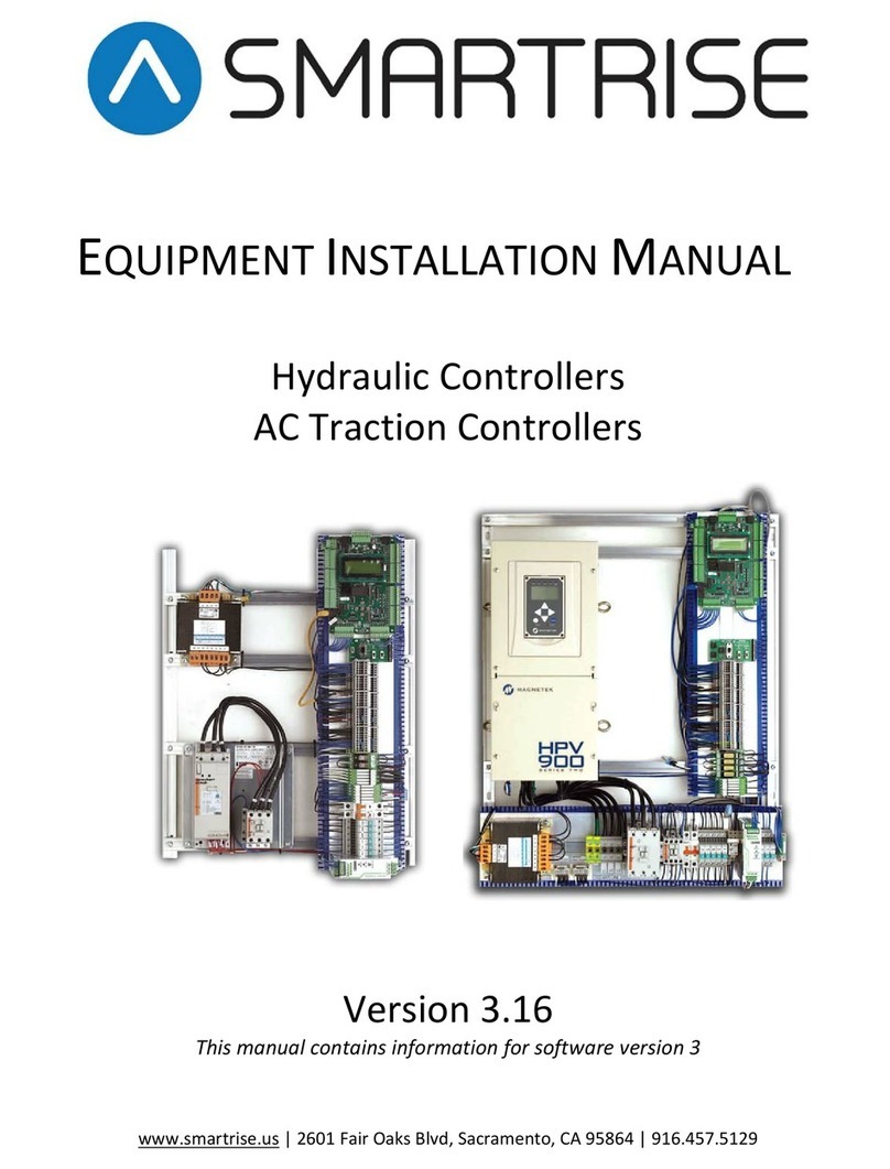
Smartrise
Smartrise F220 Technical Document

Smartrise
Smartrise HYDRO:EVOLVED User guide

Smartrise
Smartrise Sprecher + Schuh Installation and operation manual
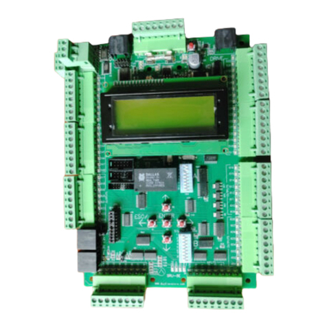
Smartrise
Smartrise SRU Installation manual

Smartrise
Smartrise HYDRO:EVOLVED User manual

