ISO 9001
Sistemi di regolazione automatica per:
condizionamento/riscaldamento/processo termico industriale.
The performances stated in this sheet can be modified without any prior notice due to design improvements
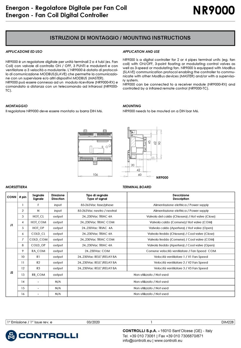
Function in the Description
“OFF” pos. “ON” position
1 2-10 Vdc 0-5 Vdc Feedback signal
2 Modulating Increase/decrease Control (not at Sequence)
3 – Sequence Sequence control
4 0-10 V 2-10 V Voltage range
5 1-5 V, 4-7 V 6-9 V, 8-11 V Part of voltage range
6 60 s 300 s Running time
7 Normal Inverted Direction of movement
8 Normal Linear/Logarithmic Valve characteristic
9 Operation End position adjust Operation/End position adjustment
There are nine switches in a row on the
circuit board. On delivery (’Factory’), all
switches are in the “OFF” position.
1 Feedback signal — 2-10 / 0-5 Vdc
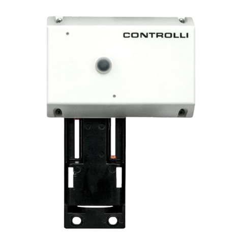
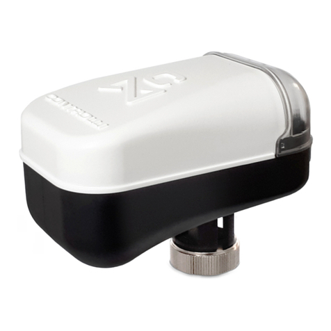
MVHFA actuators are equipped with a 2
-10 and 0-5Vdc position feedback signal
selectable by Switch No 1.
2 Control signal—MOD / INC
Actuator can either be controlled by a
variable direct voltage, a so called mod-
ulating signal (MOD), or by an increase/
decrease signal (INC).
3 Sequence or parallel control—
– – – / SEQ
Withsequence(orparallel)control(SEQ),
twoactuators/valvescanbecontrolledby
only one control signal.
For each of these you can choose which
part of the voltage range to use, the up-
per one, 6-9 V (8-11 V) or the lower one,
1-5 V (4-7 V).
If the switch NORM / INV is in NORM
position, the higher voltage corresponds
to 100% flow and the lower one to 0%.
With NORM / INV in the INV position you
will get the opposite function.
4 Voltage range—0-10 / 2-10
Youcanchoosewhethertousethecontrol
signal voltage range 0-10 V or 2-10 V.
5 Part of voltage range—
0-5, 2-6 / 5-10. 6-10
You can choose which part of a volt-
age range to use, the lower one 1-5 V
(4-7 V) or the upper one 6-9 V (8-11 V).
If the switch is in the NORM position, the
highervoltage correspondsto100% flow
and the lower one to 0%. To achieve the
opposite function, the switch should be
put in its INV position.
6 Running time—60 s / 300 s
With increase/decrease control, you can
choose a running time between 60 s or
300 s.
With modulating control, the running time
is always 15 s / 20 s / 30 s.
7 Direction of movement—
NORM / INV
WhenNORMisselected,thespindleofthe
actuator moves inwards when the control
voltage decreases or if the actuator gets
a decrease signal.
WiththeswitchNORM/ INV,the direction
of movement can be changed.
8 Linearization—NORM / LIN/LG
Themotorizedvalvecharacteristicscanbe
modified.Ifyouwishforthecharacteristics
tobeaffected,thesettingLIN/LGwillmake
the characteristics of an equally modified
percentage (EQM) valve almost linear.
On the other hand, with LIN/LG a motor-
izedvalveequippedwithalinearvalvewill
operatewith”Quickopencharacteristics”.
Thismeansthatwithasmallcontrolsignal,
the valve will be almost completely open.
9 End position adjustment—OP / ADJ
This switch is only used to adjust the end
positions when the actuator is commis-
sioned.
With powered actuator, momentarily put
theswitchintheONposition.Theactuator
willautomaticallyfind theend positionsof
the valve.At the end of the adjustment all
the other dip switch settings (1 to 8) will
be read again.
Note! For the actuator to register new
settings of the switches, the supply
voltage must be cut, the settings done
and then the power on
or
the end position adjustment must be
done again (see point 9).
Refer also to illustration on page 2.
(This does not apply to the switch OP/
ADJ).
1st Issue rev. e 02/13 5 DIM152e
