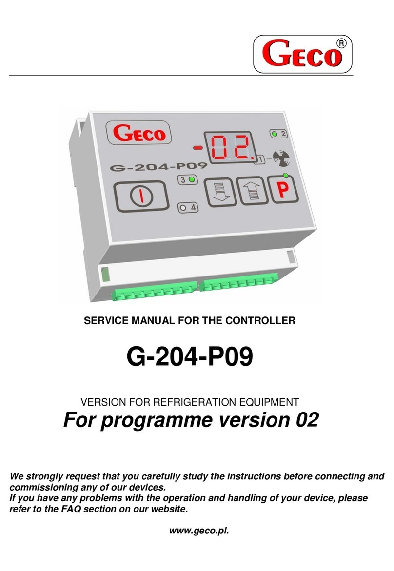
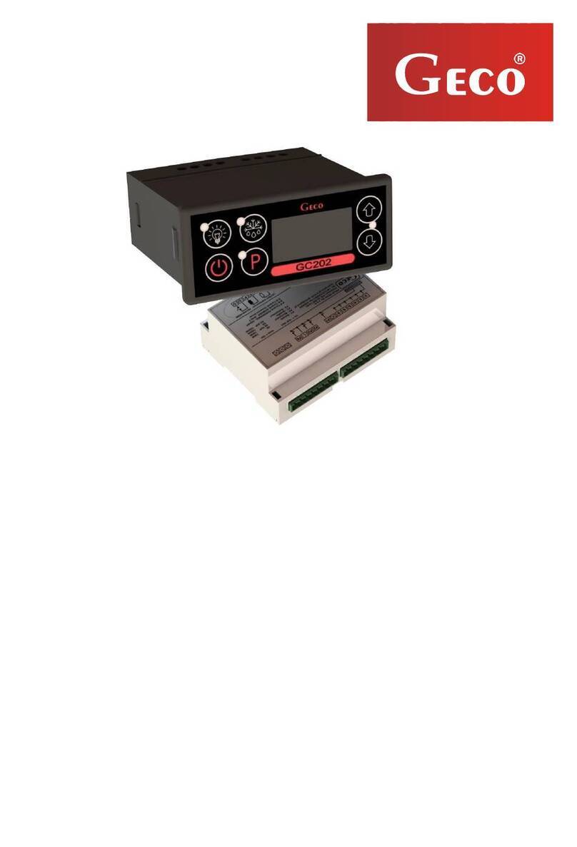
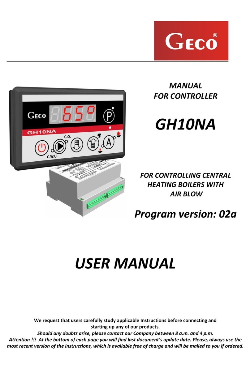
Geco G-202-P05 Installation guide

INSTALLATION, OPERATING AND MAINTENANCE MANUAL
G-202-P05
COOLING APPLIANCES CONTROLLER
For software releases 01,02,03
We kindly request that you study this manual carefully PRIOR to connecting and starting
up any of our equipment. Should you have any queries or doubts, please contact us
between 8 a.m. and 4 p.m. Any comments e-mailed will be appreciated.

Page 2 Revision I FROM 2012-09-20
Table of Contents
I. GENERAL FEATURES....................................................................................................................................................3
II. MARKING AND SPECIFICATIONS .............................................................................................................................3
III. ORDERING INFORMATION.....................................................................................................................................4
IV. DELIVERY, INSTALLATION AND CONNECTION..............................................................................................5
V. INSTALLATION OF SENSORS, TYPES OF COVER SHELLS.................................................................................6
VI. GENERAL OPERATION PRINCIPLES ...................................................................................................................6
VII. ON/OFF DIAGRAMS FOR INDIVIDUAL ASSEMBLIES OF THE APPLIANCE..............................................9
VIII. SETTING THE SYSTEM PARAMETERS..............................................................................................................10
IX. G-202 OPERATION - USER INSTRUCTIONS ......................................................................................................12
X. TROUBLESHOOTING...................................................................................................................................................13
XI. RETURNING FOR REPAIR .....................................................................................................................................14
XII. SOFTWARE RELEASE CHANGES........................................................................................................................15
XIII. 12 DEC. 2002 –RELEASE 02. CHANGED OPERATION OF THE KEY. FOR DETAILS –SEE
CHAPTER VI GENERAL OPERATION PRINCIPLES......................................................................................................15
XIV. BLOCK DIAGRAM, ACTUATOR MODULE VIEW, AND EXECUTION OF THE RIBBON CABLE
CONNECTING THE CONTROL PANEL AND THE ACTUATOR MODULE................................................................16

Page 3 Revision I FROM 2012-09-20
I. GENERAL FEATURES
The Self-contained Control Block further called the G-202 is a state-of-art device, comfortable
and easy to use. The Controller is a microprocessor-based device manufactured using the Surface Mount
Technology (SMT).
The thermostat is designed for appliances using an additional fan or heater for window demisting.
The control panel with a safe 5V power supply can be installed in any convenient location, without need
for cutting additional holes and guiding many power supply cables far from the controlled appliances.
The G-202 is equipped with two temperature sensors, door sensor input, and four outputs allowing
direct connection of appliances operating at 230V with loads given in Table 1. Optionally it can be fitted
with the third sensor to control the window temperature.
The G-202 stabilises temperature and controls automatic defrosting with interval adjustable to
ambient conditions; the Controller also has a manual evaporator defrosting key.
Unlike other thermostats, the G-202 has a special key to activate window demisting.
No special maintenance is required for the thermostat; keyboard is made of special foil resistant to
high temperatures and most chemicals. Never use sharp items to clean the foil, just wipe the front panel
with a moist cloth.
II. MARKING AND SPECIFICATIONS
Model designation: G- 2 X –P 05K X X –M XXXX X
Items: 1 2 3 4 5 6 7 8 9 10 11
1- “Geco” thermostat
2- For use with cooling appliances
3- Enclosure type: 02 –minipanel, 03 –large keyboard
4- Start of designations regarding the front panel (keyboard)
5- Software release 05
6- Temperature setting: K - keyboard
7- Light key: L –installed, 0 –not installed
8- Buzzer: B –installed, 0 –not installed
9- Start of designations regarding model revision
10-Designation of installed relays. For detailed description –see below.
11-Door sensor: D –mechanical or magnetic door sensor, Y –optical door sensor, 0 –no option
for door sensor installation.
Additional information about relay designation:
Any number denotes a relay is installed, 0 –no relay installed:
1 –compressor relay –must be installed
2 –light relay
3 –window fan or heater relay
4 –programmable relay
Examples:
1030 –compressor and window fan/heater
1004 –compressor and programmable
1230 –compressor, light, window fan/heater
1204 –compressor, light and programmable

Page 4 Revision I FROM 2012-09-20
Operating voltage - 230V +10% -15%
Operating temperatures - +5°C to +40°C
Humidity - 20% to 80% RH
Ingress protection - IP65 at the front of the control panel
Table 1: Designation of relays and output loads
Output
Load
P1 - Compressor
8A
2HP
1500W
P2 - Light
4A
-
750W
P3 –Window fan/heater
4A
1HP
750W
P4 - Programmable
8A
-
1500W
Note !!!
Currents as specified in the Table are currents consumed by particular
equipment during normal operation and include starting currents of
this equipment !!!
The aggregate current consumed simultaneously may not exceed 10A !!!
III. ORDERING INFORMATION
When ordering, specify the full name of the controller, according to the designation described in chapter
II. Pay special attention to the following:
1. Enclosure type: 02 –minipanel, 03 –large keyboard
2. Specify the need for the light key: L –installed, 0 –not installed
3. Option for buzzer installation: B –installed, 0 –not installed
4. Relays you need to be installed 1 2 3 4
5. Option for door sensor connector installation:
D –connector for mechanical or magnetic door sensor,
Y –connector for optical door sensor,
0 –no door sensor installed.
Additionally, specify the following:
1. Length of the ribbon cable connecting the actuator module and the keyboard panel.
2. Length of temperature sensors.
You can also order additional door opening sensors operating in an entirely touchless manner:
a. magnetic sensor with range of 1-2 cm,
b. optical sensor with range of 1-2 cm.

Page 5 Revision I FROM 2012-09-20
IV. DELIVERY, INSTALLATION AND CONNECTION
1. In the appropriate place within the unit cut a hole of 20x30mm in size, however if masking frame
of the panel is not used the size of the hole should be 58x109mm.
2. Mount the actuator on the rail and latch it. For store equipment the SCCB actuator module
MUST be fixed to the floor!!!
3. Any metal elements, through which the G-202 or its cables are run should be ground or protected
otherwise. Fitting G-202 to enable direct action of water on it (e.g. water condensating on the
bottom cover of the shop window), touching the outlet pipe from the evaporator etc. and changing
considerably its temperature in relation to the ambient temperature (e.g. fitting in the immediate
proximity of the compressor and its accessories, cooled and heated elements) is not allowed.
4. Cut the ribbon connecting the panel with the actuator into the desired length plus 2-3cm. Then,
after running it through all penetrations, cut it once more by cutting its ends at right-angle and clip
the plugs on it so that the end of the ribbon be hidden to approx. 0.5mm. The ribbon must be
introduced perpendicular to the plug and clipped so as to make its twisting or non-parallel layout
impossible. Connecting the ribbon to the connectors see figure at the end of the instructions.
5. After fastening the G-202, connect the power cables according to the description provided on the
actuator wall. Depending on the G-202 version some outputs may be not used - on the label with
the description they will not be described and the type symbol in the corresponding places will
contain zeroes - do not connect any conductors to these outputs!!!
6. The applied connectors are certified for continuous load of 16A!!! They incorporate fine thread
and special lamellae, which prevent the wires from being cut, therefore only light tightening
ensures maximum good contact and the use of greater force may lead to stripping out of the
thread. In the result this may lead to the socket melting and short-circuit !!!
7. Any cable surplus should be cut down or winded up and clamped using special plastic bands. The
cables must be firmly secured on its entire length and must not get in contact with the compressor
and its equipment
8. After connecting the unit to the power source there can be voltage across the lighting cable
regardless of switching on or off the unit with the button therefore the starter or the
fluorescent lamp should be replaced only with the power cord disconnected from the plug!!!
THE SAME APPLIES WHEN CARRYING OUT ANY OTHER REPAIRS !!!
9. If heaters are used, their power must be fitted correctly, which means that during failure of the G-
202 or of the external contactor and switching them on for good, there were no possibility of fire
or the device damage.
If great power heaters are used then the safety thermostat must be absolutely applied on the
evaporator. This thermostat must operate on the different principle, for instance: mechanical
thermostat.

Page 6 Revision I FROM 2012-09-20
V. INSTALLATION OF SENSORS, TYPES OF COVER SHELLS
1. For each type of the manufactured equipment a place for securing the sensors and the SCCB settings
should be determined experimentally. Absolutely do not change the fastening location nor the way
the sensors are secured nor modify SCCB settings without prior carrying out new tests relating to
temperature stabilization and equipment defrosting cycle !!!
2. Fastening of the chamber sensor must be done in such a way so that it does not get in contact with
food products and is not exposed to damage when cleaning the equipment. The sensor can be fixed
using a special plastic bracket. This solution causes fast (on/off time delays see VI p. and 5 and 7)
response of the sensor and the entire thermostat to the change in the air temperature in the unit. When
desired or necessary to slow down and "smooth" the time of sensor response to the temperature
changes we recommend to fix it to the metal part of the unit.
3. Fasten the evaporator sensor in the way to ensure maximum and good contact with the evaporator
lamella and in place where ice remains for the longest time during defrosting. Its fastening should
prevent it from being pushed out by the growing ice. The sensors, wherever possible, should be fixed
vertically so that the cable exits from the bottom of the sensor.
4. Sensor cables can be shortened or extended in any way, however with respect to the following
rules:
-do not cut the sensor cable at a section smaller than 0.5 m. From the case
-it is not recommended to extend the sensor cable to more than 20 m.
-THE SENSOR CABLES CAN BE CONNECTED TO THE TERMINALS OF THE
ACTUATOR SENSORS IN ANY WAY!!!
(in the same way as you connect the plug to the ~230V outlet)
-for cable extension we recommend using OMY 2x0.5 mm type conductor
-connect the extended cables with great care, by soldering each pair of cores and put thermally
shrinkable jackets on them. Then apply water-proof silicone on the joint and clamp one more
thermally shrinkable jacket on it.
-whiten the ends of the conductors connected to SCCB with tin
VI. GENERAL OPERATION PRINCIPLES
A - General Information
1. After connecting power supply the device performs a 3-second initialising procedure during which the
display shows two dots for a second, controller software release for another second, and two dots
again. During that time none of the connected appliances are switched.
2. After completion of the above initialising procedure, the middle segments of the display show two
dashes indicating “powered” condition – if the device was not powered before!!! The device is started

Page 7 Revision I FROM 2012-09-20
by pressing the key. The display shows value of the temperature indicated by the chamber
sensor.
3. If you press and hold the or keys for 0.5 second, the display will start flashing and showing the
temperature setting –this is the temperature programming mode; press the or again to change
the temperature setting. After 5 seconds from the last key press, the G-202 returns to temperature
reading mode and stores the new temperature setting.
If the G-202 is turned off during the programming mode, the new temperature setting will not be
stored.
4. Compressor activation is indicated by lighting of a small LED (dot) in the lower right corner of the
temperature display. This allows easier checking of possible system malfunctions.
5. If the compressor activation fails due to activation of one of the protections (see sections 6, 7, 10 and
11), the compressor activation dot will flash. After the protection times-out, the dot lights permanently
and the compressor is switched on.
6. The delay in compressor activation after reaching its activation temperature (the user temperature
setting plus lower hysteresis value) is 30 seconds. If the temperature drops during that period, the
system re-checks if the 30-second condition has been exceeded. This is to protect the compressor from
unnecessary activation caused by e.g. putting goods in, draughts etc.
7. Every time when the temperature setting is reached (the user temperature setting plus the upper
hysteresis value) and after every power outage or drop below 175V, the G-202 allows to re-activate
the compressor for the time determined by the ‘c2’ parameter. However, if the ‘c2’ = 0min, then the
protection after power outage continues for 60 seconds.
8. When you switch on the appliance using the key, a 5-second delay in compressor activation
occurs. Please note, that when you use this to cancel the power outage described in (7) above –this
will also refer to the time set in the ‘c2’ parameter when the compressor was turned off before. This
allows quicker checking of the compressor operation.
9. The Controller is equipped with alarms indicating sensor failures. Behaviour of the Controller
depends on which sensor has failed:
Failure of the chamber temperature sensor causes the A1 alarm display. The Controller will
activate the compressor in time-cycle (the so called “clock control”) according to the ‘c8’ and ‘c9’
time settings. Defrosting will operate normally.
Failure of the evaporator sensor causes the A2 alarm display. Operation of manual and
automatic defrosting is disabled!!! The only way to defreeze the appliance is to turn it off using
the key and wait until ice melts naturally.
If two sensors fail simultaneously, only the A1 alarm will be indicated. When the chamber
temperature sensor is repaired, the A2 alarm is shown.
10. If the Controller has an integrated buzzer –see chapter II, the Controller beeps at every key press. If
the Controller is off (two dashes on the display) the buzzer will beep only at the and key
presses.
11. You can turn the light on and off using the key. This is indicated by lighting of a green LED at
the key. If the light is switched on due to door opening, this LED does not light. The key operates
independently from the thermostat current switch .
12. Software release 01:
Pressing the key lights the LED at the key and activates the window heater or fan. Pressing it
again turns off the LED and the window heater/fan.
Software release 02:
Short pressing of the key lights the LED at the key and activates the window heater or fan.
Another short press turns off the LED and the window heater/fan. If you press and hold the key
for about 1 second, the evaporator temperature monitoring is activated. This condition is indicated by
a flashing LED at the key. The temperature monitoring times-out after 30 seconds or you can exit
by pressing the key again.
Software release 03:

Page 8 Revision I FROM 2012-09-20
Short pressing of the key turns on the LED at the key and activates the window heater or fan.
After the time set in ‘d4’ the window demisting is automatically deactivated. If the parameter ‘r6’ is
set to 3, then the window temperature is also stabilised.
Another short press turns off the LED and the window heater/fan.
If you press and hold the key for about 1 second, the evaporator temperature monitoring is
activated. This condition is indicated by a flashing LED at the key. After 15 seconds the window
temperature monitoring is activated –if the ‘r6’ is set to 3, and the condition is indicated by display
flashing. This stage also takes 15 seconds. If the parameter ‘r6’ is other than 3, then there is no
window temperature sensor monitoring.
B - Defrosting
1. If you need to perform additional defrosting due to difficult operating conditions, press the
key. This will cause constant lighting of the green LED at the key, and the display will show
“dF” instead of temperature reading. This causes the appliance to enter the defrosting cycle.
2. If the defrosting is active and the evaporator temperature is higher than the ‘d2’ parameter setting,
then the appliance will enter the defrosting phase after about 10 seconds, and once completed,
returns to normal operation.
If the defrosting function is active and the evaporator temperature is lower than the ‘d2’ parameter
setting, the G-202 activates defrosting, and when the ‘d2’ temperature setting is reached, the Controller
enters the defrosting exit procedure (this condition is indicated by flashing of the green LED at the
key) consisting of a single dripping phase –when the compressor remains off for the time set in
the parameter ‘c3’.
3. The defrosting is complete when the evaporator temperature reaches the ‘d2’ temperature setting
or when the time exceeds the value stored in the parameter ‘c1’.
4. Once the “dF” is off and the defrosting is finished, the display will read the temperature stored
just before the defrosting process for the time set in the parameter ‘c7’ – this is to prevent claims
that may occur due to “sudden temperature changes in the appliance”.
5. The system behaves similarly in both manual and automatic defrosting.
C –Door opening sensor operating principle
1. When the door is opened the fan is immediately stopped and the light may be switched on
depending on the ‘r7’ parameter setting in the G-202. Temperature reading is shown in the
display.
2. After 30 seconds, if the door remains open, the display will continuously show a “dr” message.
For the controllers with buzzer installed, a short beep is emitted and repeated every 30 seconds.
3. If the door still remains open, then after the time set in the parameter ‘r8’ an alarm is activated
which is indicated by display flashing with the “dr” message, and in controllers with buzzer
installed –with an acoustic warning signal. At the same time the compressor is switched off.
4. If the ‘r8’ = 0, then the alarm is activated immediately after opening the door.
5. You can cancel the alarm by pressing any key. Closing the door deactivates the alarm and restores
normal operation.
6. The Controller allows to connect both a mechanical door opening sensor, which is closed when
the door opens (r6=01), as well as a mechanical or magnetic sensor which is opened when the
door is opened (r6=02).
HYSTERESIS
When programming the parameters ‘d0’ and ‘d1’ (minimum and maximum temperatures that can be set
by the user) you should also remember that the hysteresis value ‘d3’ causes additional “dragging” of the
temperature down and up from the value set by the user.

Page 9 Revision I FROM 2012-09-20
This is especially important for the “positive temperature” appliances that must always operate at
temperatures above 0°C.
As a manufacturer of a cooling appliance, in this case a cooling counter (positive temperatures), we
require that the device enables operation only within the range of temperatures that do not exceed the
below specified values: Switching off at min. 2°C. Switching on at max. 10°C
Symmetrical hysteresis for even values of ‘d3’
Symmetrical hysteresis for odd values of ‘d3’
Example 1.
Assume the hysteresis ‘d3’ is set to e.g. 2°C.
For the above hysteresis setting you should also
set the parameters: ‘d0’ to 3°C and ‘d1’ to 9°C
Example 3.
Assume the hysteresis ‘d3’ is set to e.g. 3°C.
For the above hysteresis setting you should also set
the parameters: ‘d0’ to 3°C and ‘d1’ to 8°C
Example 2.
Assume the hysteresis ‘d3’ is set to e.g. 4°C.
For the above hysteresis setting you should also
set the parameters: ‘d0’ to 4°C and ‘d1’ to 8°C
Example 4.
Assume the hysteresis ‘d3’ is set to e.g. 5°C.
For the above hysteresis setting you should also set
the parameters: ‘d0’ to 4°C and ‘d1’ to 7°C
VII. ON/OFF DIAGRAMS FOR INDIVIDUAL ASSEMBLIES OF THE
APPLIANCE
For individual assemblies the thick line means On and the dashed line means Off.
The field “Standstill” means off, while the “Operation” field means activation of the compressor due to
exceeded programmed temperature, of course including the hysteresis programmed in parameter ‘d3’.
INCORRECT PARAMETER SETTING CAUSES ERRONEOUS OPERATION OF THE
APPLIANCE !!!
1. fan operating together with the compressor r1’=01
t=c3
KOMPRESOR
WENTYLATOR
Postój Praca ROZMRAŻANIE WYJŚCIE Z ROZMRAŻANIA Praca Postój
2. fan operating continuously ‘r1’=02,
Turn-on temperature
Temperature set
by the user
‘d3’
Turn-off temperature
‘d3’
½‘d3’+0.5ºC
½‘d3’-0.5ºC
½‘d3’
½‘d3’

Page 10 Revision I FROM 2012-09-20
t=c3
KOMPRESOR
WENTYLATOR
Postój Praca ROZMRAŻANIE WYJŚCIE Z ROZMRAŻANIA Praca Postój
3. evaporator heater ‘r1’=03,
t=c3
KOMPRESOR
GRZAŁKA
Postój Praca ROZMRAŻANIE WYJŚCIE Z ROZMRAŻANIA Praca Postój
4. tray heater ‘r1’=04,
t=c3
KOMPRESOR
GRZAŁKA TACKI
Postój Praca ROZMRAŻANIE WYJŚCIE Z ROZMRAŻANIA Praca Postój
Kompresor
Compressor
Wentylator
Fan
Grzałka
Heater
Grzałka tacki
Tray heater
Postój
Standstill
Praca
Operation
Rozmrażanie
Defrosting
Wyjście z rozmrażania
Exiting defrosting
VIII. SETTING THE SYSTEM PARAMETERS
Once the device is started and checked for proper operation (default settings are factory set) you can
begin to enter the system parameters of the G-202.
Firstly, turn off the device with the key. Then press and hold the and keys and press the
key. Keep all three keys pressed for 3 seconds. Releasing any of the keys during that period will
cause exiting the programming mode. After that the LEDs at the keys and should start flashing,
and the display should show a flashing message ‘c0’. Then the previously value set for the parameter will
be shown. Now use the keys to enter the settings; press and hold the key to fast change of the value.
Then use the key to accept the entered data and move on to the next parameter.
The settings can be programmed partially, and if you don’t want to change a setting, simply press the
key and the G-202 will move on to the next parameter.
Note !!!
The refrigeration unit Manufacturer may block access to a portion of or even to all
parameters available from the keyboard, by means of the computer programming unit. If
this is the case, and the alteration of any of the blocked parameters is attempted, the
display will show the ‘bL’ symbol for the period of 1 second.

Page 11 Revision I FROM 2012-09-20
Table 2: Designation of parameters
Parame
ter
Description
Min.
Max.
Step
Factory
setting
c0
Setting of the defrosting interval. Note !!! If you set this to
“0”, there will be no automatic defrosting, only the
manual!!! If you set this to “-01”, there will be no defrosting
at all, neither automatic nor manual!!!
00
-01
24
1h
6h
c1
Maximum defrosting time, if the evaporator does not reach
the set temperature (parameter d2). Note !!! When this
parameter is set to “-01” the duration is not limited.
00
-01
99
1min
30min
c2
Minimum compressor standstill duration
00
15
1min
3min
c3
Evaporator dripping duration
00
15
1min
2min
c4
Window drying duration.
NOTE!!! When this parameter is set to “0” the window
drying duration is not limited!!!
0
60
1min
5min
c5
Maximum compressor operation duration
0 –means there is no test (the parameter is disabled)
00
99
1min
40min
c6
Compressor standstill duration after activation of protection
set in parameter ‘c5’
0
99
1min
10min
c7
Duration of showing the temperature measured just before
the defrosting, shown immediately after the defrosting
(parameter ‘c4’).
00
60
1min
5min
c8
Duration of compressor operation in case of control sensor
failure
01
99
1min
25min
c9
Duration of compressor standstill in case of control sensor
failure
01
60
1min
5min
d0
Minimum temperature the user can set
-40
20
1°C
1°C
d1
Maximum temperature the user can set
d0+1
39
1°C
10°C
d2
Evaporator temperature at which the defrosting is finished
0
40
1°C
5°C
d3
Hysteresis value
1
10
1°C
2°C
d4
Value of chamber sensor re-scaling from the actually
measured temperature
-10
10
1°C
0°C
d5
Temperature stabilised at the window (maximum window
temperature)
1
20
1°C
2°C
d6
Temperature hysteresis at the window.
1
10
1°C
2°C
r1
Devices connected to the 4th relay:
00 –none
01 –fan operating together with the compressor
02 –fan operating continuously
03 –evaporator heater
04 –tray heater
00
04
1
00
r5
Conditions for defrosting activation during the device start:
00 –start of operation without defrosting
01 –if a power outage occurred during the defrosting, the defrosting
is activated
02 –defrosting after every powering on of the device.
00
02
1
00
r6
Door opening sensor / or additional temperature sensor option:
00 –no door opening sensor
01 –door opening sensor exists, closed at open door
00
02
1
03

Page 12 Revision I FROM 2012-09-20
02 –door opening sensor exists, open at open door
03 –temperature sensor at window
r7
Lighting activation methods:
01 –light controlled only by the door sensor
02 –light controlled only by the keyboard
03 –light controlled by both the door sensor and the keyboard
01
03
1
03
r8
Time elapsed after door opening until alarm activation.
After 30 seconds from door opening the “dr” message is shown. For
the controllers with buzzer installed, a short beep is emitted and
repeated every 30 seconds.
After the ‘r8’ time is elapsed the alarm is activated and indicated by
flashing “dr” message on display, and for the controller equipped
with buzzer –an acoustic signal is emitted; the compressor is
switched off.
0 –means immediate alarm activation
0
20
1min
1min
r9
Door opening sensor connection location:
01 –sensor connected to the actuator module
00 –sensor connected to the control module. Note: in this
configuration you have to order a special cable with plug!!!
00
01
1
01
IX. G-202 OPERATION - USER INSTRUCTIONS
1. After connecting the device to the power supply the display will show two dots for one second, then
the software release, and the dots again for another second. Following that, two dashes will be shown
in the middle segments of the display, indicating that the device is powered. The device is started by
pressing the key. The display shows value of the temperature indicated by the chamber sensor.
3. Setting of the temperature.
Press and hold one of the keys for at least 0.5 second to enter the temperature programming
mode. The display will start to flash and show the previously programmed setting.
Use the keys to change the temperature setting. Press and hold a key to fast change the
displayed value.
If you don’t press any of the keys for 5 seconds, the Controller exits the programming mode
and stores the new settings.
3. You can activate and deactivate the operating mode with drying using the key; the greed LED
lights to indicate activation of the operating mode with drying.
NOTE –IMPORTANT !!!
If you need to perform additional defrosting due to difficult operating conditions, press the key.
The green LED at the key will light, the display will show “dF” instead of temperature, and the
device will enter the defrosting cycle.
The defrosting procedure will be finished automatically when its time elapses or upon reaching of the
temperature set by the manufacturer of the cooling appliance.
Performing unauthorised repairs will invalidate the warranty and may lead to electric shock
and hot vapour burns. Therefore refer all repairs to authorised and trained service
technicians!!!

Page 13 Revision I FROM 2012-09-20
X. TROUBLESHOOTING
Symptoms
Checks
1. The display is off
even if G-202 is
connected to the
power supply
Check:
- if 220V voltage is present on the power supply terminals L and N
- correct connection of the actuator to the control panel
- remove and reinsert the ribbon sockets
- connect another ribbon
2. The compressor
will not start despite
its power-on
signaling
-red LED
Check:
- 220V voltage presence on terminals K and N - If present, then check
the compressor
- if not, then check correct connection of the actuator with the control
panel
- connect another ribbon
3. Defrosting heater
does not switch on
Check:
- if there is voltage 230V on clamps as described on the casing of the
controller
- if there is, check the heater
- if not then check the connection of the executive module with a control
panel
- connect another ribbon
4. Drying heater
doesn’t switch on.
Check:
- presence of the 230V voltage at the terminals marked in the description
provided on the upper panel of the actuator module
- if not, then check for correct connections between the actuator module
and the control panel
- replace the ribbon cable
5. Incorrect
temperature
reading
Check:
- sensor connections to terminals
- value of the parameter ‘d4’
- correct installation of the sensor
- sensor cable condition –the cable must not have any signs of damage
- carefully examine the outer shell of the sensor for any signs of
mechanical damage
6. Can’t set the
required
temperature
Check:
- value of the parameters ‘d0’ and ‘d1’ (d0<d1)
7. Flashing dots on
display, can’t turn
on
Check:
- value of the power voltage
- condition of power connectors
- tightening of power connectors
- correct connection of the actuator module with the control panel
- replace the ribbon cable
8. Abnormal,
unusual behaviour
of the device
Check:
- presence of 230V voltage at the power supply terminals L and N
- condition of power connectors
- neutral wire connection of the cooling device
- condition of the electrical system and number of appliances connected
to the same phase

Page 14 Revision I FROM 2012-09-20
- if the type of thermostat (output description label) is correct for your
device
- if the control panel, actuator module or ribbon cable connectors were
exposed to water or other liquid
- if the control panel, module or ribbon cable connectors are exposed to
moisture or sudden changes of temperature
- correct connection of the actuator module with the control panel
- replace the ribbon cable
9. Problems with
appliance
defrosting
Check:
- value of the parameters ‘d2’ and ‘c0’, ‘c1’
- value of the parameter ‘c1’. It’s the maximum defrosting duration for the
appliance, regardless whether or not the evaporator has reached its
programmed end of defrosting temperature (parameter ‘d2’). If this
duration is too short, the appliance will not be able to defrost completely.
- correct mounting of the sensor to the evaporator lamellas.
IT MUST BE FIRMLY MOUNTED AND TIGHTLY ADHERE TO THE
LAMELLAS !!!
- if the evaporator sensor is mounted where ice remains for the longest
time, and if not, check the temperature at the sensor at the moment
when the last pieces of ice fall from the evaporator. THIS
TEMPERATURE SHOULD THEN BE ENTERED AS THE PARAMETER
‘d2’
10. The appliance
does not reach its
set temperature
and its cooling
function is not
working
Check:
- what is the temperature set by the user
- values of specific parameters, especially the ‘c2’, ‘c5’, ‘d0’, ‘d1’
- item 9 - Problems with appliance defrosting. If the appliance does not
defrost completely, it will not reach its set temperature !!!
- location and mounting of the chamber sensor
- if the there are removed side glass panels in the rack or front glass
panels in the cabinet
- IF THE APPLIANCE STANDS IN DROUGHT OR DIRECT
SUNLIGHT!!!
- if there are fans or air conditioners installed on the ceiling or around
- condenser cleanness
- temperature in the shop (every manufacturer provides the max.
operating temperature for the appliance)
- amount of gas, fans, evaporator heater, evaporator water drain hose
11. Incorrect
operation of the
door opening
sensor
Check:
- value of the parameters ‘r6’ and ‘r7’, ‘r9’
- correct sensor connection
- if the sensor is connected to the actuator module, check for correct
connection of the actuator module with the control panel
- replace the ribbon cable
XI. RETURNING FOR REPAIR
In case of failure and return of the G-202 for repair, you must completely fill the
replacement form appended at the end of this manual. We suggest to make a copy of
the form instead of cutting it out.

Page 15 Revision I FROM 2012-09-20
PPUH ‘GECO’ reserves the right to refuse a free repair of the unit, if
there is no form, the form is not filled in completely or the seals are
broken !!!
P.P.U.H. ‘Geco’ Sp. z o. o. is not responsible for loses and damages resulting
from provision of information on the method of making changes in the system
data of G-201 by the producer or its service to the final client, incorrect or non-
professional assembly and for loses caused by defective operation of the
appliance.
XII. SOFTWARE RELEASE CHANGES
XIII. 12 Dec. 2002 –Release 02. Changed operation of the key. For details –see chapter VI
GENERAL OPERATION PRINCIPLES
.
8.Feb. 2005 –Release 03. Added parameters c4, d5,d6, extended parameter ‘r6’. Option for
connection of the third temperature sensor.

Page 16 Revision I FROM 2012-09-20
XIV. BLOCK DIAGRAM, ACTUATOR MODULE VIEW, AND EXECUTION OF
THE RIBBON CABLE CONNECTING THE CONTROL PANEL AND THE
ACTUATOR MODULE
Table of contents
Other Geco Controllers manuals