manuals.online logo
Brands
  1. Home
  2. •
  3. Brands
  4. •
  5. SMD
  6. •
  7. Controllers
  8. •
  9. SMD BMD-20DIN User manual

SMD BMD-20DIN User manual

SMART MOTOR DEVICES
https://www.smd.ee
DC brush motor controller
BMD-20DIN
manual
BMD.20.DIN.001
2019
BMD-20DIN
DC brush motor controller
User manual
Tallinn Science Park Tehnopol, Akadeemia tee 21/6,
Tallinn 12618, Estonia Phone: + 372 6559914,
e-mail: sale@smd.ee
url: http://smd.ee
1. Product designation
Controller BMD-20DIN is an electronic device to operate and control DC brush motors with maximum
voltage 24VDC and power under 480W. The controller is designed to control speed, direction, smooth start
and stop of brush motors. BMD-20DIN provides the function of precise adjustable motor overcurrent
protection.
2. Technical characteristics
Power supply: 12…24VDC, stabilized;
Max. operation motor current: 20A;
Maximum voltage across a motor: 0.99∙Usup;
Minimum non-zerovoltage across a motor: 0.01∙Usup;
Overcurrent protection:
·hardware short-circuit protection - 30A, 15 µs;
·motor phase current limit – set by customer, limitation range 0.1 – 20 A, actuation time – 5 sec. Refer to
the section 5 for instruction on motor overcurrent protection setting.
Protection of an actuating mechanism:
·emergency stop (HARD_STOP) - the motor stops immediately in case the protection circuit is broken.
Thermal protection:
·output stage temperature rise;
·brake circuit temperature rise.
Speed regulation:
·analog voltage signal: 0…5 VDC;
·external potentiometer 2.2 kOhm;
·built-in potentiometer.
Input signals “DIRECTION” and “START/STOP” parameters:
·type - clean contact;
·max. current: 0.5 mА.
Environmental conditions:
·Ambient environment: non- corrosive, non-explosive,
·Humidity: 90% RH or less upon condition +25°C
·Condensation and freezing: none
·Pressure: 650…800 mm of mercury.
·Ambient Temperature: 0…+50°C
Fig.1 Dimensions of BMD-20DIN
BMD-20DIN
DC brush motor controller
User manual
Tallinn Science Park Tehnopol, Akadeemia tee 21/6,
Tallinn 12618, Estonia Phone: + 372 6559914,
e-mail: sale@smd.ee
url: http://smd.ee
3. Construction and control elements
BMD-20DIN is designed as a circuit plate with electronics elements, installed on a plate and covered
with a plastic case. Besides electronic components, there are indicating and control elements and connection
terminals on the board:
- terminal screws for power supply, motor windings and control circuit connection;
- “START/STOP” and “REVERSE” buttons;
- Internal preset potentiometers to adjust motor speed “SPEED”, acceleration/deceleration “a” and
motor current limit “I”.
- LED for indication of the controller status.
To adjust motor speed the internal potentiometer “SPEED” and the analog input for voltage signals
0..5V are provided. To adjust acceleration and reversing deceleration internal potentiometer “a” is provided.
To change motor direction the input and the button “DIR” are intended. To start or stop motion the button and
the input “START/STOP” are intended. Adjustment of the protection operation threshold 0.1 ... 20A is carried
out by the "CURRENT ADJUST" potentiometer and the "Vref" terminal.
4. Operation principle
Regulation of speed and the direction of rotation of a DC brush motor is carried out by change of
voltage value and polarity. This is achieved by including the motor in a bridge circuit on transistor switches
controlled by the PWM method.
The PWM generator is based on a microcontroller. In addition to the PWM controller, the
microcontroller performs the functions of measuring the values of the signal parameters at the control inputs,
the positions of the regulators, calculating the speed, acceleration and braking according to the internal
program.
5. Assembly and connection.
Please, learn this manual carefully before connection and assembly.
Please, wire just when power is off. Do not attempt to change wiring while the power is ON.
Please, provide a reliable contact in connection terminals. During wiring, please, observe the polarity
and wire management.
IMPORTANT: due to high current it is strongly recommended to place a power supply in direct
proximity to the controller BMD-20DIN. It is obligatory to use wire cross-section 3 mm2(AWG-8). The power
supply must be able to provide the current 20% higher than a maximum possible current consumption while in
operation. Recommended wire length: no longer than 100 cm for current up to 10A; no longer than 50 cm for
current from 10A to 20A.
The connection scheme example is shown in figure 2.
Fig.2. BMD-20DIN connection scheme (example of speed control by an external potentiometer.)
BMD-20DIN
DC brush motor controller
User manual
Tallinn Science Park Tehnopol, Akadeemia tee 21/6,
Tallinn 12618, Estonia Phone: + 372 6559914,
e-mail: sale@smd.ee
url: http://smd.ee
1) Make sure the power supply is turned off. Please, wire just when power is off.
2) Select input signals logic (refer to the section 7).
3) Connect the motor to the controller terminals A and B.
4) Connect the control elements to the controller according to chosen speed adjusting method:
- Internal potentiometer - additional connection doesn’t required
- External potentiometer – connect potentiometer to the contacts “SPEED”, GND and “+5V”. The
internal potentiometer “SPEED” should be turned to the end left position.
- Analog signal 0…5 VDC – connect the source of analog signal 0…5VDC to the “SPEED” contacts: “-“
to the “GND” contact and “+” to the SPEED” contact. The motor speed is proportional to the signal
voltage.
5) If needed, connect control elements to the “START/STOP” and “DIR” contacts. These inputs are
clean contact.
6) Connect power supply to the controller contacts: “+”of the power supply to the terminal “VIN”, “-“ of the
power supply to the terminal “GND“.. Wire cross-section should be suitable to the motor current
consumption. We recommend using wire cross-section 3 mm2(AWG-8). Ground the power supply
unit.
7) Set speed and acceleration regulators to the end CCW position, which correspond to their minimum
values.
8) Using the potentiometer «CURRENT ADJUST», set the maximum motor current. Adjust the
«CURRENT ADJUST» potentiometer and control the set current limit by a voltmeter, connected to
«GND» and «Vref » terminals (fig.3). The motor current limitation can be calculated as:
Ilim = 0.1 + 19.9 x (VREF / 3.3)
Fig. 3. Connection of a voltmeter for setting of a motor maximum current limit.
6. Motor Control
1. Choose the method of speed regulation: internal or external potentiometer or analog voltage signal
0-5VDC.
2. Connect the motor, power supply and control elements to the controller according to the section 5.
3. Turn on the power supply. The controller is ready for operation. LED at the front panel of the
controller should solid light. Adjust the motor current limit (see the section 5).
4. Start the motor by button or input signal «START/STOP». The LED should start blinking (period 1
sec). 5. Adjust the motion parameters by using of a speed regulator, acceleration potentiometer and
direction input or button.
BMD-20DIN
DC brush motor controller
User manual
Tallinn Science Park Tehnopol, Akadeemia tee 21/6,
Tallinn 12618, Estonia Phone: + 372 6559914,
e-mail: sale@smd.ee
url: http://smd.ee
In case of short-circuit of motor phases or overcurrent 30A for 15 µs, the controller turns to an
emergency mode, deenergizes the motor and indicates the alarm by LED blinking.
In case of motor current exceeds the set limit for 5 sec, the controller also turns to an emergency
mode, Red LED is blinking.
To reset the emergency mode, reset the power supply of the controller.
7. Input signals logic
The controller BMD-20DIN provides few options for processing of input signals START/STOP and
DIR. Jumpers for selection of the necessary options are located on the electronic board under the case of the
controller.
Fig. 4. Take off the case
To open the case:
·Turn off the power supply.
·Disconnect the terminals from the controller;
·Remove the controller from the DIN rail;
·Open the controller case as shown in the fig.
4:1. Press down on the latch with a flathead
screwdriver on both sides;
2. Pull the top and bottom of the case
apart;
·Set the jumpers to the required position
As a default the controller is supplied with standard signal logic: input START/STOP is processed as
per the front edge of the signal, input DIR is processed as per the signal level.
Operation logic of the inputs "START/STOP" and "DIR" can be adjusted with the jumpers
"START_PIN" and "DIR_PIN" – fig. 5.
If the corresponding pair of contacts is closed by a jumper, their state corresponds to the “ON” value.
If the jumper doesn’t close the contacts, the state of the contacts corresponds to the value "OFF".
BMD-20DIN
DC brush motor controller
User manual
Tallinn Science Park Tehnopol, Akadeemia tee 21/6,
Tallinn 12618, Estonia Phone: + 372 6559914,
e-mail: sale@smd.ee
url: http://smd.ee
The logic of operation of the control inputs "START/STOP" and "DIR" is shown in the figure 6.
Fig. 5. START_PIN
and DIR_PIN jumpers Fig. 6. Operation logic ofinputsignals
8. Alarms indication
LED on the front panel of the controller indicates the controller operation status. In case of normal
operation the indicator is green. Green indicator blinks during motor operation (approx. 1 time per second). In
case if errors occur, the LED indicates the code of an error. The number of red blinks represents the alarm
code (refer to the table below). LED errors indication
Alarm code Alarm Alarm code Alarm
0 Normal operation 4 Internal power switches overheating
1 Out of voltage range of the
internal converter 5 Wrong motor connection or emergency
stop (HARD_STOP)
2 Short circuit in a motor phase 6 Testing version of firmware
9. Delivery in complete sets
DC brush motor controller BMD-20DIN 1 pcs
10. Warranty
Any repair or modifications are performed by the manufacturer or an authorized company.
The manufacturer guarantees the failure-free operation of the controller for 12 months since date of sale
when the operation conditions are satisfied.
The manufacturer sales department address:
Smart Motor Devices OÜ,
Tallinn Science Park Tehnopol, Akadeemia tee 21/6, Tallinn 12618, Estonia,
Phone: + 372 6559914,
e-mail: mai[email protected]
url: http://smd.ee
Date of sale: Last modified: 30.03.2023

Other SMD Controllers manuals

SMD BMD-5DIN User manual

SMD

SMD BMD-5DIN User manual

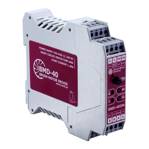
SMD BMD-40DIN User manual

SMD

SMD BMD-40DIN User manual

Popular Controllers manuals by other brands

Emerson Dixell XM668D Installing and operating instructions

Emerson

Emerson Dixell XM668D Installing and operating instructions

THORLABS SHB1 user guide

THORLABS

THORLABS SHB1 user guide

Zeagle Razor Service manual

Zeagle

Zeagle Razor Service manual

Linear Technology LTC2920-1CS5 quick start guide

Linear Technology

Linear Technology LTC2920-1CS5 quick start guide

White International Icon Series user manual

White International

White International Icon Series user manual

McIntosh MHT200 Service manual

McIntosh

McIntosh MHT200 Service manual

Siemens SIMATIC S7-1500R/H manual

Siemens

Siemens SIMATIC S7-1500R/H manual

Colnatec Eon user guide

Colnatec

Colnatec Eon user guide

Halma ALICAT LC Series operating manual

Halma

Halma ALICAT LC Series operating manual

Neets Control LiMa installation manual

Neets Control

Neets Control LiMa installation manual

Purmo NC 24 V Assembly instructions

Purmo

Purmo NC 24 V Assembly instructions

Martin Audio WX3A - SCHEMATICS user guide

Martin Audio

Martin Audio WX3A - SCHEMATICS user guide

marklin zu 29410 manual

marklin

marklin zu 29410 manual

InterHeat ITC10 instruction manual

InterHeat

InterHeat ITC10 instruction manual

Unitronics UniStream installation guide

Unitronics

Unitronics UniStream installation guide

Elko COS-1 manual

Elko

Elko COS-1 manual

HCC USB ISP1161 user guide

HCC

HCC USB ISP1161 user guide

Greyline PSL 5.0 user guide

Greyline

Greyline PSL 5.0 user guide

manuals.online logo
manuals.online logoBrands
  • About & Mission
  • Contact us
  • Privacy Policy
  • Terms and Conditions

Copyright 2025 Manuals.Online. All Rights Reserved.