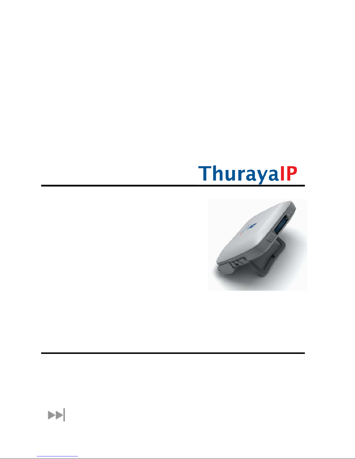
ThurayaIP Satellite Modem User Guide
v
Pacemakers
T e various brands and models of cardiac pacemakers
available ex ibit a wide range of immunity levels to radio
signals. T erefore, people w o wear a cardiac pacemaker
and w o want to use a Satellite Modem s ould seek t e
advice of t eir cardiologist. If, as a pacemaker user, you are
still concerned about interaction wit ThurayaIP, we suggest
you follow t ese guidelines:
•Maintain a distance of 15 cm between ThurayaIP and
your pacemaker;
•Maintain a distance of one meter away from t e front
of ThurayaIP’s antenna;
•Refer to your pacemaker product literature for
information on your particular device.
If you ave any reason to suspect t at interference is taking
place, turn off your ThurayaIP immediately!
Hearing aids
Most new models of earing aids are immune to radio
frequency interference from Satellite Modems t at are more
t an 2 metres away. Many types of older earing aids may be
susceptible to interference, making it very difficult to use t em
near a Satellite Modem. S ould interference be experienced,
maintain additional separation between you and ThurayaIP.
INFORMATION TO USER
Hug es Network Systems, LLC, declares under our sole responsibility t at t e product Hug es 9103 Satellite IP Terminal
to w ic t is declaration relates, is in conformity wit t e following standards and/or ot er normative documents: ETSI
EN 301 681 , ETSI EN 300 328, ETSI EN 301 489-1, ETSI EN 301 489-17, ETSI EN 301 489-20, IEC 60950-1. We ereby declare
t at all essential radio test suites ave been carried out and t at t e above named product is in conformity to all t e
essential requirements of R&TTE Directive 1999/5/EC.
T is device complies wit Part 15 of t e FCC Rules. Operation is subject to t e following two conditions: (1) T is
device may not cause armful interference, and (2) T is device must accept any interference received, including
interference t at may cause undesired operation.
T is equipment as been tested and found to comply wit t e limits for Class B Digital Device, pursuant to Part 15 of
t e FCC Rules. T ese limits are designed to provide reasonable protection against armful interference in a
residential installation. T is equipment generates and can radiate radio frequency energy and, if not installed and
used in accordance wit t e instructions, may cause armful interference to radio communications. However, t ere
is no guarantee t at interference will not occur in a particular installation. If t is equipment does cause armful
interference to radio or television reception, w ic can be determined by turning t e equipment off and on, t e user
is encouraged to try to correct t e interference by one or more of t e following measures.
•Reorient or relocate t e receiving antenna
•Increase t e separation between t e equipment and receiver
•Connect t e equipment into an outlet on a circuit different from t at to w ic t e receiver is connected
•Consult t e dealer or an experienced radio/TV tec nician for elp
Any c anges or modifications not expressly approved by t e party responsible for compliance could void t e user’s
aut ority to operate t e equipment.