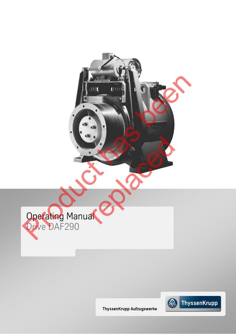
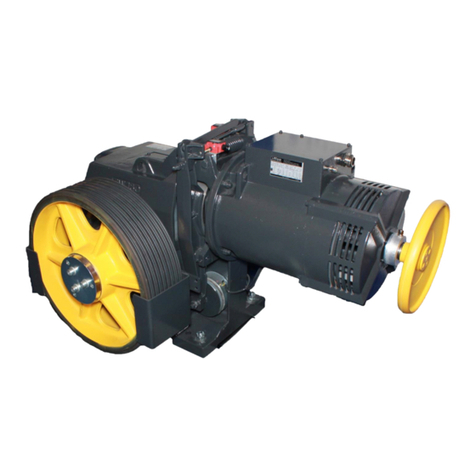
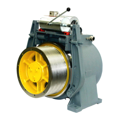
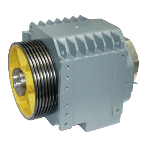
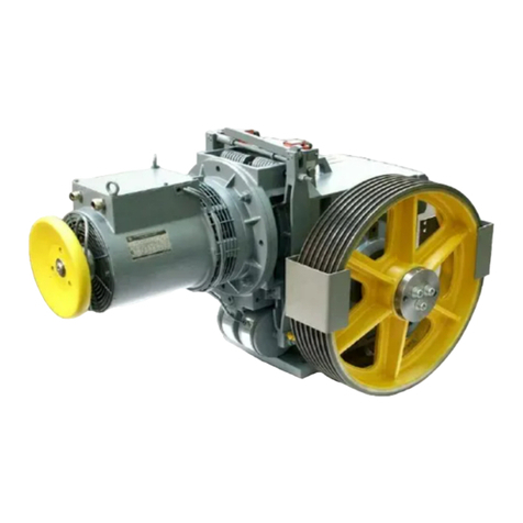
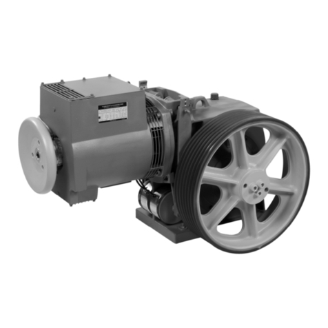
ThyssenKrupp TW63B User manual

thyssenkrupp Aufzugswerke
Operating manual
TW63B drive

Legal information
All rights reserved
© Copyright by thyssenkrupp Aufzugswerke GmbH
Note on industrial property rights ISO 16016
Printed in Germany
This document –including excerpts –may only be reprinted or otherwise copied with the
express approval in writing of thyssenkrupp Aufzugswerke GmbH.
Any duplication, dissemination or storage on data media unauthorised by thyssenkrupp
Aufzugswerke GmbH is an infringement of copyright and shall give rise to prosecution.
Subject to change without notice
We expressly reserve the right to make changes of a technical nature for the purpose of
improving our products or enhancing the safety standard - even without a separate
announcement.
Choice of colours
The choice of colours used in our documents for the components is solely for illustration
purposes in the documentation.
Contact your thyssenkrupp Aufzugswerke sales partner for details of colours for your specific
products.
Form of address
To improve readability, a gender-specific form of address has not been used. Gender-specific
pronouns therefore refer to both men and women.
Issued by
thyssenkrupp Aufzugswerke GmbH
Bernhäuser Strasse 45
73765 Neuhausen a. d. F.
Germany
Tel.: +49 7158/12-0
E-mail: Doku.elevator.plant.de@thyssenkrupp.com
Internet: www.thyssenkrupp-elevator-eli.de

Operating manual Table of Contents
TW63B drive
thyssenkrupp Aufzugswerke Version 05/2016
Table of Contents
1About these instructions...................................................5
1.1 Guide to layout................................................................................ 5
2Safety..................................................................................6
2.1 Warning notes................................................................................. 6
2.2 Safety requirements........................................................................ 7
2.3 Warranty and liability....................................................................... 8
2.4 Dangers in handling the product ..................................................... 9
2.5 International occupational health and safety regulations................10
2.6 Personal protective equipment.......................................................11
3Product Description.........................................................12
3.1 Standards and legal requirements..................................................12
3.2 Description .....................................................................................12
3.3 Functional description ....................................................................17
4Technology.......................................................................20
4.1 Technical data................................................................................20
4.2 Dimensions of machine..................................................................21
4.3 Machine base frame.......................................................................25
4.4 Machine base frame dimension sheets..........................................29
4.5 Encoder..........................................................................................38
4.6 Brake..............................................................................................39
5Transportation and storage............................................40
5.1 Packaging ......................................................................................40
5.2 Transport........................................................................................41
5.3 Checking the delivery.....................................................................43
5.4 Packaging materials.......................................................................44
5.5 Ambient conditions.........................................................................44
5.6 Standstill maintenance...................................................................44
6Installation........................................................................45
6.1 Setting up the machine base frame................................................45
6.2 Installing and aligning the machine ................................................46
6.3 Mounting the rope guard................................................................48
6.4 Connecting motors.........................................................................49
Operating manual Table of Contents
TW63B drive
thyssenkrupp Aufzugswerke Version 05/2016
7Commissioning................................................................53
7.1 Work steps.....................................................................................53
7.2 Emergency operation.....................................................................54
8Servicing / Maintenance..................................................56
8.1 Maintenance period........................................................................56
8.2 Maintenance measures..................................................................56
8.3 Lubrication......................................................................................57
8.4 Checking the backlash...................................................................59
8.5 Replacing the brake shoes.............................................................61
8.6 Setting and checking the brake shoe stroke and armature base
plate ...............................................................................................63
8.7 Braking deceleration setting...........................................................65
8.8 Brake readjustment in the event of brake lining wear.....................65
8.9 Replacing the traction sheave........................................................66
8.10 Replacing the motor.......................................................................68
8.11 Replacing the encoder ...................................................................69
8.12 Check for escaping grease / oil......................................................71
9Special versions (optional).............................................73
9.1 Overview of SA special versions....................................................73
9.2 Brake monitoring circuit..................................................................74
10 Appendix...........................................................................79
10.1 Blocking clamp...............................................................................79
10.2 Tightening torques..........................................................................80
10.3 Front page Operating Manual Emergency Brake System NBS......81
10.4 Front page Operating Manual Explosion-proof machines (ATEX)..82
10.5 Manufacturer specifications Wachendorff, encoder WDG 100H ....83
10.6 Manufacturer specifications mayr, ROBA-stop-z............................89
10.7 Manufacturer specifications Centaflex..........................................103
10.8 Manufacturer specifications Lapp cable gland SKINTOP MS-SC-
M..................................................................................................105

Operating manual About these instructions
TW63B drive
thyssenkrupp Aufzugswerke 5 Version 09/2018
1 About these instructions
1.1 Guide to layout
Sequence of actions involving several steps
1. First action.
2. Second action.
Interim result (optional)
3. Third action.
4. Final action step with end marker.
Result of action (optional)
Course of action with independent steps
Action step.
Action step.
Action step.
Information
Information must always be read and observed.
Reference
Chapter 2
List
Superordinate item of a list
Subordinate item of a list
Superordinate item of a list

Operating manual Safety
TW63B drive
thyssenkrupp Aufzugswerke 6 Version 09/2018
2 Safety
2.1 Warning notes
Warning notes are intended for the protection of persons and property.
Warning notes must be read and observed by every person who works on the
product.
Warning notes precede activities that pose a hazard for people and the product.
2.1.1 Structure
SIGNAL WORD AND SIGNAL COLOUR
Type and source of danger!
Consequences if danger disregarded.
Measures to avert the danger.
2.1.2 Identification of personal injury
DANGER
Danger with a high degree of risk!
If ignored, leads to death or serious injury.
Read and observe warning.
WARNING
Danger with a high degree of risk!
May lead to death or serious injury.
Read and observe warning.
CAUTION
Danger with a low degree of risk!
May lead to minor or moderate injury.
Read and observe warning.
2.1.3 Identification of damage to property
NOTE
Hazard with possible damage to property!
May lead to product function impairments or function loss.
Read and observe warning.

Operating manual Safety
TW63B drive
thyssenkrupp Aufzugswerke 7 Version 09/2018
2.2 Safety requirements
This document contains important information for safe operation of the product.
Keep this document and all other applicable documents at the location of use for
the entire working life of the product.
2.2.1 Area of applicability
This document applies only to the product described here.
Other applicable documents
International occupational health and safety regulations
2.2.2 Basic requirements for safety
All existing safety devices are to be tested regularly in accordance with the
maintenance schedule.
This document, in particular the chapter entitled “Safety", together with the
warning notes and all other applicable documents must be observed by all
persons who work with the product.
Supplementary to this document, the rules at the location of use with regard to
environmental protection, and the regulations of work safety and accident
prevention must be observed.
All safety and hazard notices on the installation must be kept in legible condition.
Safety information and instructions required by law must be displayed to users in
plain view.
A requirement for safe handling and non-disruptive operation of this product is
knowledge of the fundamental safety regulations.
2.2.3 Obligations of the operating company and installation firm
Only deploy trained and instructed qualified personnel.
Provide personnel with the required personal protective equipment.
Check personnel at regular intervals to ensure that they follow safety-conscious
work practices and comply with national provisions.
Make all other applicable documents as well as this document available to
personnel.
2.2.4 Duties of personnel
Clearly establish all areas of responsibility prior to any activity.
Always wear the personal protective equipment made available to you.

Operating manual Safety
TW63B drive
thyssenkrupp Aufzugswerke 8 Version 09/2018
2.3 Warranty and liability
The 'General Terms of Sale and Delivery' of thyssenkrupp Aufzugswerke GmbH
apply.
The product is configured in the factory and delivered ready for operation.
Warranty and liability claims in the event of injury or damage to property will be
invalidated if attributable to at least one of the following causes:
Improper use that is not in line with the intended purpose of the product.
chapter 2.3.1
Improper installation, commissioning, operation and maintenance of the product
Operation of the product with defective or inoperative safety devices, guards or
protection devices
Noncompliance with the information and instructions in the operating manual in
respect of transport, storage, installation, assembly, commissioning, operation
and maintenance
Structural modification to the product without agreement or approval
Modification to product features without agreement or approval
Deficient monitoring of parts that are subject to wear
Repairs that are carried out improperly
Cases of catastrophe due to third-party interference or force majeure
Use on non-approved auxiliary materials and operating fluids
2.3.1 Use in line with intended purpose
The product has been constructed using state-of-the-art technology and in line with
the recognised technical safety regulations. It may only be used in accordance with its
intended purpose and when the technical safety devices are in satisfactory condition.
Any other or additional form of use shall be regarded as non-compliant with the
intended use. thyssenkrupp Aufzugswerke GmbH shall not be liable for any damage
arising from such use and any damage arising due to operator errors.
To comply with the intended use of the product:
Use the product only as a drive for elevators.
Read and comply with the document, in particular the chapter entitled “Safety",
together with the warning notes and all other applicable documents.
Follow the commissioning instructions, observe the installation description and
maintain the required inspection and maintenance work.

Operating manual Safety
TW63B drive
thyssenkrupp Aufzugswerke 9 Version 09/2018
2.4 Dangers in handling the product
The traction sheave and handwinding wheel of the TW63B are designed without
safety covers. This means that the drive may only be operated in a closed room.
It must be ensured when persons are in the vicinity of the machine that there is
adequate safety clearance to all revolving parts (marked in yellow).
With the vertical version, do not place any objects (e.g. tools etc.) on the
handwinding wheel, as there is a risk of injury as a result of parts being thrown.
In the event of improper use, there is a risk of personal injury or to the life of the
user or third parties, or impairment on the subassembly or other assets can
arise. Malfunctions that can impair safety must be rectified immediately.
When working on the drive, it must be de-energised before work is started, and
the system must be secured against inadvertent switching on.
A sign indicating that maintenance work is under way on the drive must be
attached in the area of the main switch.
Emergency brake, NBS:if an emergency brake NBS is fitted, the sequence and
procedure for emergency rescue change. This also applies to testing and setting
up procedures. Follow the instructions in the separately supplied operating
manual.
The shaft version of the machine (MRL) usually has no manual release (possible
as an option). It can only be operated with suitable electrical additional measures
that are not included in the scope of supply.
Suitable measures must be taken by the manufacturer of the elevator
installation:
to be able to operate the brake in emergencies (power failure).
to enable release of the car from the engaged position if the safety gear is
triggered. (For example, by means of a winching device for ropes on the elevator
car or counterweight.)
to be able to carry out an individual check of the two brake circuits.
It must be ensured that a fault generated by the encoder, the brake or the brake
activation is detected by the elevator control or frequency inverter. The control
system must immediately place the elevator in a safe state.
The elevator system must be fitted with a safety device complying with EN81 or
that detects unintended elevator car movement with the door opened and
initiates suitable measures.

Operating manual Safety
TW63B drive
thyssenkrupp Aufzugswerke 10 Version 09/2018
2.5 International occupational health and safety regulations
Table 2.5-1
International rules for occupational health and safety can also be found in various
languages on our ELI web platform and can be downloaded at:
http://www.thyssenkrupp-elevator-eli.de/nc/de/downloads.html

Operating manual Safety
TW63B drive
thyssenkrupp Aufzugswerke 11 Version 09/2018
2.6 Personal protective equipment
Danger
Cause (examples)
Risks
Remedy
Equipment
Unprotected shaft
Fall
Safety harness
Falling tool
Suspended load
Transport of heavy load
Sharp-pointed objects
Head injury
Head
protection
Falling tool
Suspended load
Transport of heavy load
Sharp-pointed objects
Danger of crushing
in the foot area
Cut or stab injury in
the foot area
Foot protection
Sharp objects
Mechanical parts
Sharp-pointed objects
Caustic substances
Cut or stab injury in
the foot area
Danger of crushing
in the foot area
Cut or stab injury in
the hand area
Acid / alkali burns
Hand
protection
Severe noise pollution
Noise damage
Ear protection
Flying parts
Flying particles
Laser beams
Optical beams
Eye injury
Loss of
sight/blinding
Eye protection
Electrical voltage
Electric shock
Enable source
of energy
Table 2.6-1

Operating manual Product Description
TW63B drive
thyssenkrupp Aufzugswerke 12 Version 09/2018
3 Product Description
3.1 Standards and legal requirements
EN81-1:2010-06
The TW63B machines comply with the European standard EN81-1:2010-06 and
EN81-20/50.
The drive is part of the protection device according to DIN EN81-1:2010-06 / 9.11 and
EN81-20/5.6.7.
3.2 Description
3.2.1 Version with vertical motor position IMV1
TW63B Machine with motor version V3F (shown is the vertical IMV1 motor position -
and brake monitoring - SA3/3.1)

Operating manual Product Description
TW63B drive
thyssenkrupp Aufzugswerke 13 Version 09/2018
Description of items for Fig. 3.2-1
Item
Designation
Item
Designation
1
Driving gear (vertical version)
2
Traction sheave (standard
version)
3
Motor of type IMB5/V1 in
accordance with building code
BV6530-06/Bl.6 with integrated
special flange (standardised
motors) or BV6530-06/Bl.1 with
additional intermediate flange
4
Operational brake
5
Encoder (type WDG100) with V3F
6
Handwinding wheel (D270) with
V3F and/or flywheel rim with AC2
7
Rope guard (adjustable)
8
Oil drain (3/4")
9
Oil filling hole and ventilation
(R3/4")
10
Oil level monitoring (gauge glass)
11
Traction sheave mount
12
Connection for motor and
temperature monitoring
13
Intermediate terminal and
connection of the operational
brake (only available for the
standardised motors)
14
Mounting surface for machine
base frame
15
Lever for manual brake release
(not mounted)
16
Brake monitoring - SA3/3.1
(optional)
17
Motor terminal box in extended
version for intermediate terminal
connection of the operational
brake (only available for the
standardised motors)
18
Air entry openings for motor with
screen grid
19
Machine name plate
20
Motor type plate
Fig. 3.2-1

Operating manual Product Description
TW63B drive
thyssenkrupp Aufzugswerke 14 Version 09/2018
3.2.2 Version with horizontal IMB5 motor position
TW63B machine with motor version V3F (shown with horizontal IMB5 motor position)
Item
Designation
Item
Designation
1
Driving gear (horizontal version)
2
Oil filling hole and ventilation
(R3/4")
3
Oil level monitoring (gauge glass)
4
Oil drain (R3/4")
5
Mounting surface for machine
base frame
6
Transport hanger (for
transportation only)
7
Machine name plate
Fig. 3.2-2

Operating manual Product Description
TW63B drive
thyssenkrupp Aufzugswerke 15 Version 09/2018
3.2.3 Version with emergency brake, NBS
TW63B machine with NBS emergency brake system (shown in the horizontal IMB5
motor position, and left-hand traction sheave position)
Item
Designation
Item
Designation
1
Disc brake - emergency brake
system
2
Cover plate for brake
3
Socket wrench for manual release
4
Screws for manual release (screw
head marked in red)
5
Brake test switch with connection
line (length approx. 1 m)
6
Connection line for brake voltage
(length approx. 1 m)
7
Protective cover for brake
Fig. 3.2-3

Operating manual Product Description
TW63B drive
thyssenkrupp Aufzugswerke 16 Version 09/2018
3.2.4 Version for traction sheave position in the shaft (SA9)
Item
Designation
Item
Designation
1
TW63B machine, shown with
vertical motor position IMV1
2
Traction sheave shaft (SA9
version)
3
External bearing (bearing housing
with self-aligning bearing on
adapter sleeve; shown is the
vertical installation position for
upward rope pull direction)
4
Traction sheave (SA9 version)
5
Compensating support (for
statically defined machine
mounting)
6
Mounting surfaces for machine
base frame
Fig. 3.2-4
3.2.5 Versions
Vertical upright (IMV1) motor position with traction sheave position on left
Horizontal motor position (IMB5) with traction sheave position on left/right
The following versions of the machine can be selected depending on customer
requirements:
Gear reduction
Traction sheave version
Motor version
Motor arrangement (vertical / horizontal)
Version of encoder

Operating manual Product Description
TW63B drive
thyssenkrupp Aufzugswerke 17 Version 09/2018
3.3 Functional description
The TW63B machine (B = generation) is only operated with IMB5 motors.
Machine with worm gear, anti-friction bearings, lubrication with synthetic gear oil for
traction elevators
3.3.1 Gear
The gear (gear drive) consists of a single-stage worm gear mounted on roller
bearings. The housing is in monoblock design with a bearing bracket integrated on
one side or on both sides and integrated dual-circuit brake. The worm gear toothing
runs in oil. The traction sheave is overhung.
3.3.2 Drive
Depending on the version, the drive comes from a three-phase motor standing (IMV1)
vertically on the gear or flange-connected horizontally (IMB5) on the gear to the worm
shaft, via worm wheel, traction sheave shaft to the traction sheave.
3.3.3 Drive motors
The drive motors are designed as device category IMB5 / V1 to accommodate the
motor. PTC thermistors are installed in the motor to provide protection against thermal
overloads.
3.3.4 Connection
The connection of the thermal motor monitoring and operational brake is located in
the motor terminal box.
More details on the motor can be found in
chapter 6.3
3.3.5 Type of drive
As standard, the TW63B is delivered with a frequency-controlled three-phase motor.
An encoder for speed monitoring can be supplied as an option. This is fitted on the
motor shaft.
Technical data and manufacturer specifications of the offered encoder versions can
be found in
chapter 9.2.4.
In the case of drives for the machine room (TWR), a handwinding wheel is firmly
mounted
For deployment on non-controlled installations, a version with pole changing motor
(AC2 4/16-pin) with flywheel rim is available.
3.3.6 Coupling
Worm shaft and rotor shaft of the motor are connected by a flexible coupling. This
transfers the driving motion to the brake rotor of the disc brake.
3.3.7 Brake
The dual circuit shoe brake is spring actuated. Two independently acting brake shoes
press the brake lining onto the brake disc with spring force preset on the system.
The braking force is configured in such a way that one of the brake shoes is sufficient
to bring an elevator car loaded with full weight to a standstill.

Operating manual Product Description
TW63B drive
thyssenkrupp Aufzugswerke 18 Version 09/2018
The brake is released by electrically operated magnetic clamps with armature base
plate.
Release by manual operation
1. Apply the supplied brake release lever to the cast-on recesses of the ends of the
brake blocks.
2. Press the lever in the direction of the machine in the direction of the arrow (see
Fig. 3.3-1).
This presses the brake shoes apart, releasing the brake.
Item
Designation
1
Brake shoes
2
Brake release lever
Fig. 3.3-1
3.3.8 Emergency braking device NBS
The optional version of the emergency brake (NBS) meets the requirements for the
protection device that prevents overspeed in the upward-moving elevator car in
accordance with DIN EN81-1:1998 / 9.10 or DIN EN81-20/5.6.6 and unintended
elevator car movements in accordance with DIN EN81-1:2010-06 / 9.11 (EN81-1/A3)
or DIN EN81-20/5.6.7.
Details of the emergency brake (NBS) can be found in a separate operating manual
that is supplied if the brake is fitted.
3.3.9 Traction sheave
The one-part traction sheaves are fastened overhung on the traction sheavehaft by
using a cone (1:15) and a mounting plate including 3 screws (M16-8.8
microencapsulated with locking washer).
Different versions of traction sheave are used, depending on the location of the
machine.
Standard version - Traction sheave position in the machine room
Special version SA9 - Traction sheave position in the shaft
2
1

Operating manual Product Description
TW63B drive
thyssenkrupp Aufzugswerke 19 Version 09/2018
unit
mm 510 590 520
mm 110
7 x8
7 x9
6 x10
5 x11/12
5 x13 3)
°
kg 60 70 50
1) Version in accordance with product description groove profiles with hardened groove flanks (min. 50 HRc).
2) With minimum groove clearance - RAmin in accordance with product description groove profiles
3) with Tmin for hardened grooves in accordance with product description groove profiles TW63_30301_ENG
max. number of grooves - z xd 2)
6 x8
8 x9
6 x9
7 x10/11
450
96
132
6 x133)
4 x13 3)
technical data
name
material
weight
groove type
rim width - B
diameter - DT
5 x10/11
6 x12 3)
4 x12 3)
special alloyed EN-GJL 250
50
angle of the vee grooves
seat / vee groove 1)
standard / SA9
9 x8
machine design
70
depends on order 1)
675
Table 3.3-1

Operating manual Technology
TW63B drive
thyssenkrupp Aufzugswerke 20 Version 09/2018
4 Technology
4.1 Technical data
unit
mm
°
kg
TW63_30101_ENG
synthetic gear oil
SM1
(polyalkyleneglycol with additives)
l
horizontal motor position: approx. 9
technical data
54:1 / 48:1 / 33:1 / 48:2 / 43:3
ThyssenKrupp Elevator
TW63B
oil filling
weight
axle distance
type of oil
approx. 190
vertical motor position: approx. 11
155
manufacturer
gear type
gear ratio
name
0.025 - 0.07
designation
circumfer. backlash
Table 4.1-1
Machine with vertical motor position: Ft 43 kN,
i.e. no restriction
Weight
Standard version of motor in IMB5/V1 design.
Components
Values
Gear drive (without traction sheave)
approx. 180 kg
Gear drive SA 9 (without motor, without traction sheave)
approx. 220 kg
Gear drive
(without motor, with traction sheave depending on size)
approx. 230 - 250 kg
Traction sheave according to order 450 - 675 mm
approx. 50 - 70 kg
Motor
see motor type plate
Load data traction sheave shaft
The load values Ftzul set out below represent the limiting value of the permissible
radial load on the traction sheave shaft calculated from the overall masses present at
the installation.
Traction sheave shaft - standard version and emergency brake system Ft 43
kN
Traction sheave shaft - SA 9 (with external bearing): Ft 41 kN
For the machine with the traction sheave shaft in the standard version, there are
restrictions in place for Ft for the horizontal and vertical upwards rope departure
directions:
Machine with horizontal motor position: Ft 35 kN
Table of contents
Other ThyssenKrupp DC Drive manuals

ThyssenKrupp
ThyssenKrupp DAB450 User manual

ThyssenKrupp
ThyssenKrupp TW130 User manual

ThyssenKrupp
ThyssenKrupp rothe erde User manual

ThyssenKrupp
ThyssenKrupp Mini gearless DAF270 User manual

ThyssenKrupp
ThyssenKrupp TW160 User manual

ThyssenKrupp
ThyssenKrupp DAF 380 User manual

ThyssenKrupp
ThyssenKrupp TW63 User manual

ThyssenKrupp
ThyssenKrupp DAF290 User manual
Popular DC Drive manuals by other brands

Hitachi
Hitachi DKC710I-CBXA Maintenance manual

GFA
GFA ELEKTROMAT ST 30.24-40,00 installation instructions

Vari
Vari JM 4-003 V manual

DEA SYSTEM
DEA SYSTEM LATO 220NET Operating instructions and warnings

Fantom Drives
Fantom Drives Venom8 product manual

Siemens
Siemens SIMOREG DC-MASTER operating instructions