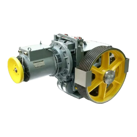
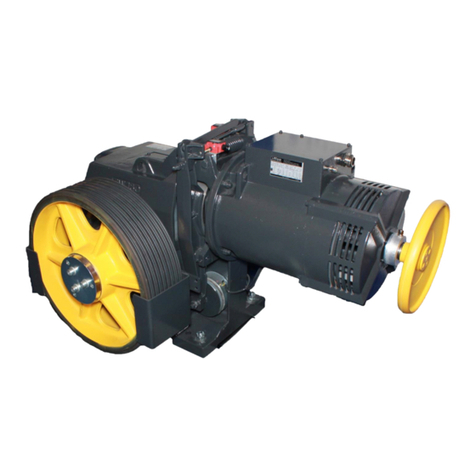
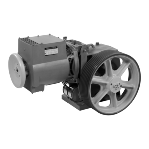
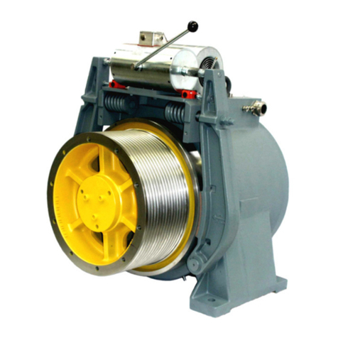
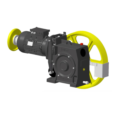
ThyssenKrupp Mini gearless DAF270 User manual

Operating Manual
Mini gearless®DAF270
ThyssenKrupp
ThyssenKrupp Aufzugswerke
A company o
f
ThyssenKrupp
Elevator


OPERATING MANUAL
ThyssenKrupp Aufzugswerke GmbH 3Issue 06.2004
Imprint
All rights reserved
Copyright by: THYSSENKRUPP AUFZUGSWERKE GmbH
P.O. box 23 03 70, D-70623 Stuttgart
Printed in Germany, June 2004
The copyright of this documentation rests with THYSSENKRUPP AUFZUGSWERKE
GmbH. This documentation or extracts of it shall not be copied, distributed or used for the
purpose of competition.
Any reprint, copying or storing in data processing machines in any form or by any means
without prior permission of THYSSENKRUPP AUFZUGSWERKE GmbH is regarded as
infringement of the current Copyright Act and will be prosecuted.
Technical modifications for reasons of improvement or higher standard of Mini gearless®
DAF270 are subject to decisions of THYSSENKRUPP AUFZUGSWERKE GMBH
without prior notice.
The responsibility for the content lies with the editor:
THYSSENKRUPP AUFZUGSWERKE GmbH
Preface
We are pleased that you decided to purchase a quality product from THYSSENKRUPP
AUFZUGSWERKE GmbH.
This operating manual assists you in getting familiar with the drive for moving cars - the
Mini gearless®DAF270 (which is referred to as DAF270 below) - and its intended
possibilities of use. Important information concerning safety and hazards helps you to
safely use the DAF270.
DAF270 is subject to technical alterations.


OPERATING MANUAL
ThyssenKrupp Aufzugswerke GmbH 5Issue 06.2004
Table of contents
Mini gearless®DAF270 PAGE
1. Safety
1.1 Explanation of symbols used 6
1.2 General safety information 7
2. Transportation and storage 10
3. Product description
3.1 Description of DAF270 12
3.2 Functional description 14
3.3 Technical data - machine 17
3.4 Technical data - brake 20
3.5 Pulse encoder 21
3.6 Dimensions 22
3.7 Machine frame 25
3.8 Lubrication 27
3.9 Name plate 28
4.Mounting of machine
4.1 Mounting of machine 30
4.2 Motor connection 32
4.3 Connection of magnetic brake 33
4.4 Connection of encoder 39
4.5 Schematic diagram 40
5. Putting into service
5.1 Putting machine into service 41
6. Servicing
6.1 Servicing of machine 42
6.2 Drive brake test 43
7. Maintenance
7.1 Replacing of traction sheave 47
7.2 Replacing of pulse encoder 49
7.3 Replacing of brake monitoring switch 51
7.4 Silencing of brakes 51
7.5 Replacing of brakes 52
8. Annex
8.1 Tightening torque – mechanical strength 55
8.2 Manufacturer's instructions for pulse encoder 56
8.3 Manufacturer's instructions for magnetic brake 61
8.4 Type test examination certificate for brake 66
8.5 Declaration of conformity for brake 70
8.6 Type examination certificate for
calculation of traction sheave shaft 72

OPERATING MANUAL 1. SAFETY
ThyssenKrupp Aufzugswerke GmbH 6Issue 06.2004
1.1 Explanation of symbols used
The following pictographs and designations are used in this operating manual:
Danger
This symbol draws attention to an extreme danger to
life or risk of injury to persons.
Disregard of warning means danger to life!
Danger
This symbol draws attention to an immediate
impending danger to life or risk of injury to persons
caused by electric current.
Warnings must always be observed!
Warning
This symbol draws attention to an impending danger.
Disregard can cause injury to persons or extensive
damage to property.
Warnings must always be observed!
Note
This symbol draws attention to important information
and instructions for operation. Disregard can lead to
damages, hazards or failures.
Inspection
This symbol draws attention to the proper inspection
sequence.
These inspection notices must be observed in any
case. Disregard can lead to injury to persons or
damage to property.

OPERATING MANUAL 1. SAFETY
ThyssenKrupp Aufzugswerke GmbH 7Issue 06.2004
1.2 General safety information
Information on the operating manual
Knowledge of the basic safety requirements is a prerequisite for the safe use
and fail-free operation of this component.
This operating manual comprises the most important information how to
safely use the component.
The operating manual and, in particular, the safety information must be
observed by all persons who perform any work on the component.
In addition the rules and requirements concerning the regulations for
prevention of accidents which apply to the installation location must be
observed.
Duties of the owner and / or the installer
The owner and / or the installer ensure that only persons are authorized to
work at the component, who
•are familiar with the requirements concerning safe working and prevention
of accidents and who were trained how to use the component.
•have read the safety information and the warning notices in this operating
manual.
Note: check the compliance of the employees method of working with the
safety requirements in regular intervals.
Duties of the employees
Persons who are authorized to perform work at the component are obliged
•to observe the requirements concerning safe working and prevention of
accidents;
•to read the safety information and the warning notices in this operating
manual prior to start working.
Training of the employees
Only trained and instructed, technically competent persons shall perform
work at the component.
The competence of the employees must be clearly defined for all tasks
concerning putting into service, operation, maintenance and repair work.
Organizational measures
The owner or the installer must provide the necessary personal protective
gear. All existing safety devices must be checked regularly in accordance
with the maintenance plan.

OPERATING MANUAL 1. SAFETY
ThyssenKrupp Aufzugswerke GmbH 8Issue 06.2004
Informal information about safety measures
•The operating manual must always be available at the location of the
installation.
•The general and local regulations for the prevention of accidents and
environmental regulations must also be made available and observed.
•Clearly and easily visible statutory safety instructions must be made
available for the users.
•See to it that all information concerning safety and hazards is always
visibly and legibly made available on the machine.
Use as intended
DAF270 is designed in accordance with the state of the art and the
recognized safety regulations. DAF270 shall only
•be used for its intended purpose
•be used only if safe operation is ensured
DAF270 shall exclusively be used as drive for lifts.
Any other use or any use exceeding the scope of above definitions is
regarded as use outside of the intended purpose. THYSSENKRUPP
AUFZUGSWERKE cannot be hold liable for any damages resulting from this
and for any damages which are caused by any errors of procedure.
Use within the scope of its intended purpose also comprises
•observance of all information of the operating manual
•fulfilment of the instructions applying to putting into service, installation
description and inspection and repair work.
Guarantee and liability
The "General Conditions and Terms of Sale" of THYSSENKRUPP
AUFZUGSWERKE GmbH apply generally.
Any claims for guarantee and liability are excluded in the case of injury to
persons or damage to property resulting from one or several of the causes
below:
•use of DAF270 outside the scope of its intended purpose
•inexpert mounting, putting into service, operating and maintaining of
DAF270
•use of DAF270 with defective and/or non-operative safety and
protective devices
•disregard of the instructions in the operating manual that apply to
transportation, storage, mounting, putting into service, operation and
maintenance of DAF270
•unauthorized constructional modifications of DAF270
•unauthorized modification of drive (rating etc.)
•unsatisfactory supervision of parts that are subject to wear
•inexpert repair work
•catastrophes caused by outside influences and Act of God
OPERATING MANUAL 1. SAFETY
ThyssenKrupp Aufzugswerke GmbH 9Issue 06.2004
Constructional modifications at DAF270
DAF270 is adjusted at the factory and delivered ready for work.
In the case of any modifications of the machine THYSSENKRUPP
AUFZUGSWERKE GmbH cannot be hold liable.
Use of DAF270 and possible hazards
DAF270 shall only be operated in a closed machine room, provided with
cover and rope guard at the traction sheave or installed in a machine frame
in the headroom. The owner of the installation must verify that the drive is
accessible to trained experts only.
Works at the drive shall only be performed with the drive disconnected from
power supply and the installation protected against unintentional switching
on.
See to it that the safety distance to all revolving parts (marked yellow) is
observed by persons working in the machine room / headroom.
Inexpert handling can cause danger to life for the user or third parties resp.
impairment of the component or material property.
Failures which possibly impair the correct functioning are to be eliminated
immediately.

OPERATING MANUAL 2. TRANSPORT AND STORAGE
ThyssenKrupp Aufzugswerke GmbH 10 Issue 06.2004
2. Transport and storage
Packing:
DAF270 is delivered:
a) without machine frame; assembled on a wooden pallet and wrapped in foil.
b) machine and frame assembled and wrapped in foil; wooden edges or a
special pallet screwed below the machine frame.
Remove these transport contrivances before you install the machine on
site.
Transport:
Machine and frame must be perfectly horizontal and the safety precautions
observed.
Transport by means of fork lift:
•The forks must be of proper length to prevent the machine from tilting.
•See to it that the forks are attached to the frame or transport pallet and
not to the machine.
•Pay attention to projecting parts! There is the risk of injury to persons or
damage!
Transport by crane:
•Do not stay below suspended loads!
•Fasten transport chains or ropes at the machine frame.
See to it that the machine is perfectly horizontal.
•Fasten at transport aid and secure against tilting. Do not lift the motor
housing!
•Remove transport aids after transport.
Note the pictographs fastened on the packing or other visible places.
Top Handle with care Keep dry
Do not expose to
heat
Do not use handheld
grippers
Fasten here

OPERATING MANUAL 2. TRANSPORT AND STORAGE
ThyssenKrupp Aufzugswerke GmbH 11 Issue 06.2004
Dimensions and weight
The weight is indicated on a sticker on the packing of the machine.
For dimensions see delivery note.
For rough data see chapter 3.3 Technical Data
Examination by customer on receipt of goods
Examine the delivered parts for completeness, damage or anything strange.
Report and document transport damage
After receipt of goods make sure that there is no damage caused during
transport.
Information
•Immediately document the damage noticed (drawing, photograph,
description of damage).
•Immediately send the respective documents to THYSSENKRUPP
AUFZUGSWERKE GmbH.
Unpacking
Information
•Dispose packing equipment in accordance with the environmental
standards or make it available for further use.
•Special transport aids and transport contrivances remain at the
customer.
Intermediate storage
•Even if the component is not mounted directly after delivery, it should be
stored in dry places and protected with humidity-proof covering.
•Do not store the component in the open air. Parts without surface coating
lack long-time preservation.
•Open ventilation opening.
Environmental conditions
Information
Surrounding at the final site of the machine (humidity, temperature) shall
comply with the requirements for machine rooms. (Between +5° and +40°
C according to EN81).
Relative humidity of air shall not exceed 70%.

OPERATING MANUAL 3. PRODUCT DESCRIPTION
ThyssenKrupp Aufzugswerke GmbH 12 Issue 06.2004
3.1 Description of Mini gearlessDAF270
Represented without rope guard and covering
DAF270 consists of:
Pos. Part designation Pos. Part designation
1Disc on motor shaft 9Transport hole
2Cheese head screw
M12x 50
10 Cover plate for brake
3Traction sheave 11 Encoder
4Ventilation opening 12 Brake terminal box
5Casted housing 13 Encoder connection
6Thread for fastening M16 14 Electromagnetic brake
7Motor terminal box 15 Cable duct thermal contact
8Bearing bracket 16 Cable duct motor connection
3
1
76
5
4
2
Fig. 1
9
9

OPERATING MANUAL 3. PRODUCT DESCRIPTION
ThyssenKrupp Aufzugswerke GmbH 13 Issue 06.2004
DAF270 rear view
Versions:
The following versions are available:
1. Various drive capacities
2. Motors with electrical rating for inverters with sinusoidal mains
regeneration or braking operation through resistors
3. Various traction sheave diameters
4. Various groove profiles and rope number at traction sheave available
5. (Optional) machine frame variants dependent on dimensions
6. Various types of brake
10
11
12
13
14
15
58
9
Fig. 2
7
9
16

OPERATING MANUAL 3. PRODUCT DESCRIPTION
ThyssenKrupp Aufzugswerke GmbH 14 Issue 06.2004
3.2 Functional description
Machine: DAF270 consists of a frequency-controlled permanent-magnet
synchronous motor.
DAF270 has two different power ranges, which are differentiated by the letter
behind the type designation:
DAF270 M (medium) for the standard and DAF270 L (large) for the higher
power range. The external housing dimensions differ in size. See chapter 3.6
Dimensions.
The machine has a monobloc housing with integrated bearing bracket on one
side.
The drive shaft with rolling bearings is made of tempering steel.
The front self-aligning bearing and the rear rolling bearing of the bearing
bracket are sealed and life-time lubricated.
DAF270 is designed for 1 : 1 and 2 : 1 suspension with single wrap
(max.180°) and downward rope departure.
(The motor terminal box is accessible from below.) In all other cases, turn the
drives and adjust the mounting position to the respective access.
Motor: dependent on motor type and controller the braking energy can be:
a) supplied to resistors;
b) regenerated sinusoidally to the mains. (Only for motors ≥350V)
The machine is designed for thermal class F but used according to thermal
class B.
DAF270 has a self-ventilated motor (without auxiliary forced ventilation)
Operating temperature (max. 130°C ±5°C) is monitored by a posistor.
Evaluation by means of a frequency inverter. In case of overheating the drive
is de-energized through the inverter.
Traction sheave: the single-block (rim and nub) overhung traction sheave is
attached onto the conical end of the motor shaft and secured against falling
down by screw-connected disc on the front side. The micro-encapsulated
screws are protected against unintensional working loose and provided with
detent edged washers placed under.
The groove flanks are hardened as standard (≥50 HRc).
For further data see chapter 3.3 Technical Data.
The gearless machine does not have a self-locking device.
Brake: an electromagnetically operated, dual-circuit brake is attached to the
motor housing. It consists of two independently operating brake shoes
(tandem), which act onto the motor shaft.
The spring-applied armature disk of the respective magnetic brake is pressed
against the brake lining of the rotor. The rotor is pushed and the second rotor
lining acts on the rigid bearing surface of the brake or the bearing bracket.

OPERATING MANUAL 3. PRODUCT DESCRIPTION
ThyssenKrupp Aufzugswerke GmbH 15 Issue 06.2004
The two rotors are rigidly connected to the motor shaft through interlocked
holes and a hub.
Brake release: the voltage-fed brake magnet coils attract the armature discs
and release the brake rotors.
The brakes cannot be released manually.
The brake torque of each brake circuit permits to stop the car loaded with
rated load at rated speed. The brake torque cannot be adjusted.
Note: the brakes of DAF270 are designed for use as holding brake. Any
dynamic braking is restricted to emergency and test braking. Normal use will
not lead to any noticeable wear on the lining.
This drive brake can in no way replace the safety braking system used for
downward operation.
Attention: the manufacturer of the lift installation must provide proper
measures for brake connection to ensure that the brake can be tested and
emergency rescue performed (even in case of power failure).
Brake monitoring: A separate control switch monitors the momentary brake
position (released/closed) of each brake. Any failure is signaled to the
control. The machine must be shutdown or a further run prevented if the drive
either runs at zero speed with one brake circuit open or starts with one brake
circuit closed.
For terminal diagram see chapter 4.3 and adjusting of brake test switch
chapter 7.3.
An electrical safety device of the overspeed governor or a type-tested safety
device of the same safety level shall initiate the releasing of the brake in case
of overspeed if the braking device of the DAF270 is utilized as ascending
car overspeed protection means. The requirements including range of use
and conditions set out in the annex of type test certificate No. ABV 591 of
01-08-08 must be complied with. See chapter 8.4.
Real value generator: DAF270 is a synchronous machine excited by a
permanent magnet. In energized state the absolute rotor position is supplied
by a sine-cosine-wave absolute position encoder. Speed and shaft position
are detected by high-resolution sine-cosine-wave tracks.
For description of encoder and technical data see chapter 3.5 and
manufacturer's instructions in chapter 8.2.
Environmental conditions: the ambient temperature at the site of
installation shall comply with the requirements for machine rooms and thus
be maintained between +5° and +40° C (in accordance with EN 81).
The relative humidity of air shall not exceed 70%
Attention: in case of temperatures over or under the freezing point, the
braking torque of the disc brake can be reduced due to condensation.
In case of a longer standstill, the friction linings can rust at the friction
surfaces.
Corresponding counter measures are to be made by the owner of the
component.

OPERATING MANUAL 3. PRODUCT DESCRIPTION
ThyssenKrupp Aufzugswerke GmbH 16 Issue 06.2004
Machine frame: the drive DAF270 is designed for installation in the
headroom, but can also be utilized for installation in the machine room. The
machine frame necessary for installation of the machine in the headroom is
delivered optionally.
The drive is delivered completely pre-assembled.
For details concerning machine frame and installation see separate
documents for frame.
LiftEquip: LiftEquip customers obtain a project planning form with design
data and installation instructions for the machine frame.
Material number of the project planning form:
German 9720 000 6756
English 9720 000 6778
Note: an installation frame, which makes delivery of the frame into the
headroom easier, is optionally available.
Please contact LiftEquip, if interested.

OPERATING MANUAL 3. PRODUCT DESCRIPTION
ThyssenKrupp Aufzugswerke GmbH 17 Issue 06.2004
3.3 Technical data machine
1) Hardened groove flanks are used (min. 50 HRc).
Thyssen Compact gearlessDAF270
Version M 0xx L 0xx
Diameter traction sheave - DT [mm] 320 440 490
Rim width traction sheave - B [mm] 145 132 150
Max. groove number – z x d 10 x 8 7 x 10 8 x 10
Groove form traction sheave Seat or V-groove 1)
Material traction sheave EN-GJL 300 (HB 190 to 300)
2x1700Max. brake torque acc. test
certificate Mbr
[Nm] 2x1250 2x1700
Type test certificate No. of brake ABV 591
Moment of inertia gearless[kgm²] 2.10 2,90
Moment of inertia traction sheave [kgm²] 0.53 1,50 2,45
Moment of inertia machine [kgm²] 2.63 3,60 5,35
Permissible shaft load at traction
sheave Ftzul
[kN] 43.5 57 57
Weight machine (incl. traction
sheave)
[kg] 550 570 740
Weight traction sheave [kg] 35 55 65
Weight machine frame TK [kg] 400 - 650
Weight machine frame LE [kg] 400 - 600

OPERATING MANUAL 3. PRODUCT DESCRIPTION
ThyssenKrupp Aufzugswerke GmbH 18 Issue 06.2004
TYP DAF270 M 000 M 001 M 002 M 002 M 005 M008
Suspension r 2 : 1 2 : 1 2 : 1 2 : 1 2 : 1 1 : 1
Elevator speed v m/s 1.0 1.6 1.6 1.75 2.0 1.0
Traction sheave diameter DTmm 440 440 440 440 440 320
Rated output 1) PN1) kW 10.7 15.3 14.9 16.3 18.2 7.4
Rated torque MNNm 1175 1050 1025 1025 1000 1175
Speed nRot min-1 87 139 139 152 174 60
Rated current INA243035353818
Effective voltage U∼,eff V 330 350 305 330 320 330
Stator frequency fStator Hz 14.50 23.20 23.20 25.30 29.00 10.00
Efficiency (100%PN)η%838886879079
Power factor cos ϕ0.94 0.95 0.94 0.95 0.96 0.94
Starting torque MANm 2200 2200 2200 2200 2200 2200
Starting current IAA456878788934
Max. permissible current Imax.zul. A 65 90 90 90 100 49
Inverter type
(assigned as standard)
CPI26.
CPI32
CPI50R CPI48 CPI48 CPI48.
CPI602)
CPI15
Rated load (guide value) Q kg 1600 1600 1600 1600 1600 1000
1) The rated output indicated only applies to unbalanced installations under S5 operation (240 F/h, 50% Ed) with max. MA!
2) 2) With current limitation to 100A!
Pulse encoder data see chapter 3.5

OPERATING MANUAL 3. PRODUCT DESCRIPTION
ThyssenKrupp Aufzugswerke GmbH 19 Issue 06.2004
TYP DAF270 L 007 L009
Suspension r 2 : 1 2 : 1
Elevator speed v m/s 2,0 1,0
Traction sheave diameter DTmm 490 490
Rated output 1) PN1) kW 22,5
Rated torque MNNm 1375
Speed nRot min-1 156
Rated current INA 235
Effective voltage U∼,eff V 430
Stator frequency fStator Hz 26
Efficiency (100%PN)η%82
Power factor cos ϕ0,96
Starting torque MANm 2750
Starting current IAA75
Max. permissible current Imax.zul. A 100
Inverter type
(assigned as standard)
CPI50R,
CPI100R
CPI26E
Rated load (guide value) Q kg 2000 2000
1) The rated output only applies to unbalanced S5 operation (240 F/h, 50% Ed) at max. MA!

OPERATING MANUAL 3. PRODUCT DESCRIPTION
ThyssenKrupp Aufzugswerke GmbH 20 Issue 06.2004
3.4 Technical data operating brake
Type: ERS VAR09
SZ1700 / 1250
ERS VAR09
SZ1700 / 1700
Manufacturer Warner & Tourco Warner & Tourco
Brake torque 2 x 1250 Nm 2 x 1700 Nm
Version Dual-surface disc brake
asbestos-free brake
linings
Dual-surface disc brake
asbestos-free brake
linings
Operating voltage
(one brake circuit)
Without overexcitation
207 VDC voltage
103.5 VDC overexcitation
52 VDC withstand voltage
Rated output
(one brake circuit)
Without overexcitation
123 W with voltage
applied
232 W with overexcitation
59 W with withstand
voltage
Maximum ambient temperature 40°C 40°C
Max. temperature at full load 100°C 100°C
Maximum speed 250 min -1 250 min -1
Air gap (stroke per brake
circuit)
0.35 + 0.05/-0.1 mm 0.35 + 0.05/-0.1 mm
Maximum air gap in case of
wear
0.6 mm 0.7 mm
Operating time ED 60 % ED 60 %
Length of connecting line 10 m 6 m
Weight (incl. accessories) approx. 84 kg approx. 84 kg
Type test certificate number ABV 591 ABV 591
Release monitoring
(per brake circuit)
1 x microswitch
Switching voltage 24 VDC
Switching capacity 10 ÷100 mA
Operating distance at setting
screw
0.15 mm
Table of contents
Other ThyssenKrupp DC Drive manuals

ThyssenKrupp
ThyssenKrupp DAF 380 User manual

ThyssenKrupp
ThyssenKrupp TW63B User manual

ThyssenKrupp
ThyssenKrupp DAF290 User manual

ThyssenKrupp
ThyssenKrupp TW63 User manual

ThyssenKrupp
ThyssenKrupp TW160 User manual

ThyssenKrupp
ThyssenKrupp rothe erde User manual

ThyssenKrupp
ThyssenKrupp TW130 User manual

ThyssenKrupp
ThyssenKrupp DAB450 User manual
Popular DC Drive manuals by other brands

YASKAWA
YASKAWA H6R B Series Performance test manual

DANA
DANA Spicer Torque-Hub W3B Series Service manual

Aerotech
Aerotech Ndrive QL Hardware manual

Danfoss
Danfoss VLT Midi Drive FC 280 operating instructions

Bosch
Bosch Rexroth Sytronix FcP 5020 quick start guide

DART Controls
DART Controls EZ VFD CONTROL Series instruction manual