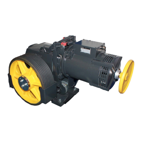
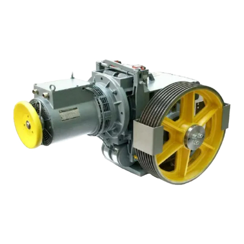
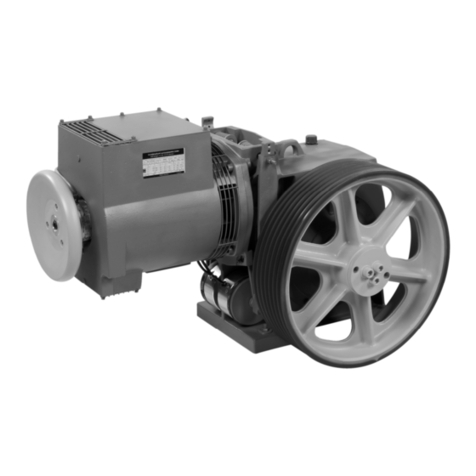
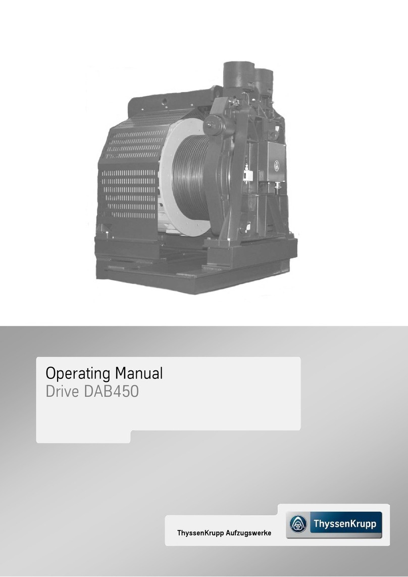
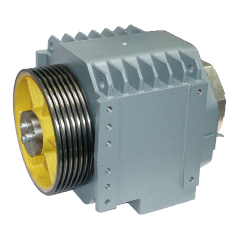
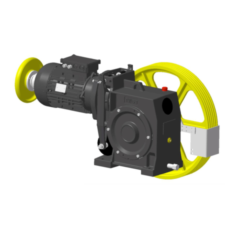
ThyssenKrupp DAF 380 User manual

ThyssenKruppAufzugswerke
OperatingManual
DriveDAF380


Company and Contact Information
All rights reserved
© Copyright by ThyssenKrupp Aufzugswerke GmbH
Protection Notice ISO 16016
Printed in Germany
This document – including excerpts – may only be reprinted or otherwise copied with
the express approval in writing of ThyssenKrupp Aufzugswerke.
Any duplication, dissemination or storage on data media unauthorised by ThyssenKrupp
Aufzugswerke GmbH is an infringement of copyright and shall give rise to prosecution.
Right to make changes of a technical nature reserved
We expressly reserve the right to make changes of a technical nature for the purpose of
improving our products or enhancing the safety standard - even without a separate
announcement.
Issued by
ThyssenKrupp Aufzugswerke GmbH
Department QPD
Bernhäuser Straße 45
73765 Neuhausen a. d. F.
Germany
Telephone: +49 (0) 71 58 12- 0
E-mail: [email protected]
Internet: www.thyssenkrupp-aufzuege.de
Intranet: http://aufzuege-
de.bucene.tke.tknet.thyssenkrupp.com/pages/tkawnetde/index.php


OPERATING MANUAL DAF380
ThyssenKrupp Aufzugswerke GmbH
List of Contents
Drive DAF380 PAGE
1. Safety
1.1 Symbols 7
1.2 Safety instructions 8
2. Product Description
2.1 Description 11
2.2 Functional description 12
3. Technology
3.1 Technical data 14
3.2 Dimensions of machine 15
3.3 Dimensions of machine base frame 16
3.4 Encoder 17
3.4.1 Encoder (2nd encoder optional ) 19
3.5 Double-vane magnet 20
3.6 Forced ventilation 20
4. Transport and Storage 21
5. Mounting the Machine
5.1 Machine setup 24
5.2 Levelling machine and machine base frame 25
5.3 Terminal connecting plans 27
6. Commissioning 29
7. Maintenance / Service
7.1 Maintenance 30
7.2 Lubrication 31
7.3. Testing the brakes 33
7.3.1Setting / checking braking deceleration 34
7.4 Setting the brake test switch 36
7.4.1 Setting the brake test switch (CSA) 37
7.5 Double brake magnet 38
7.6 Replacing the brake shoes 39
7.7 Replacing the traction sheave 40
7.8 Replacing the encoder 42
7.9 Checking for grease/oil leaks 44
7.10 Emergency measure "Releasing the car from the engaged position
(safety gear)" 46
8. Special Versions / Accessories (optional) 48
5
08-2011

OPERATING MANUAL DAF380
ThyssenKrupp Aufzugswerke GmbH
9. Appendix
9.1 Tightening torques – tightness values 49
9.2 Accessory parts 50
Type test certificate for the braking device
Declaration of conformity for the braking device
CSA - Certificate of Compliance
10. Changes 67
6
08-2011

O
PERATING
M
ANUAL
DAF380
S
AFETY
ThyssenKrupp Aufzugswerke GmbH
1. Safety
1.1 Symbols
The following pictograms and designations are used in this operating manual:
Danger
This symbol indicates extreme danger to life and the
health of persons. Nonobservance can lead to death
or severe injury!
Danger
This symbol indicates an immediate danger to the life
and health of persons due to electrical current.
Hazard warnings must always be observed!
Warning
This symbol warns against imminent danger.
Nonobservance can lead to physical injury or
extensive damage to property.
Warnings must always be observed!
Note
This symbol indicates important information and
operating instructions. Nonobservance can lead to
damage, danger or malfunctions.
Check/Test
Test steps are specified with this symbol.
The test instructions marked in this way must be
followed without fail. They contribute to preventing
personal injury or damage to property.
7
08-2011

O
PERATING
M
ANUAL
DAF380
S
AFETY
ThyssenKrupp Aufzugswerke GmbH
1.2 Safety instructions
Notes regarding the operating manual
A requirement for safe handling and non-disruptive operation of this
assembly is knowledge of the fundamental safety regulations.
This operating manual contains the most important information that is
required to operate the assembly safely.
The operating manual, in particular the safety instructions, is to be complied
with by all persons who work on this assembly.
Furthermore, the rules and regulations covering accident prevention that
apply to the installation site are to be complied with.
Obligations of the operator and/or of the installation firm
The operator and / or installation company undertakes only to allow persons
to work on the assembly who
•are familiar with the regulations regarding work safety and accident
prevention and have been instructed in handling the assembly.
•have read the chapter on safety and the warnings in this operating
manual.
Note: Check at regular intervals that the personnel work with a heightened
awareness with regard to safety.
Obligations on the part of personnel
Persons assigned to work on subassemblies undertake before starting work
to
•observe the regulations regarding work safety and accident prevention.
•read the chapter on safety and the warnings in this operating manual.
Training of the personnel
Only trained and instructed qualified personnel may work on the assembly.
The responsibility of the personnel is to be clearly defined for all tasks
involving commissioning, operation, maintenance and repair.
Organisational measures
The required personal protective equipment is to be provided by the operator
or installation firm, as the case may be. All existing safety devices are to be
tested regularly in accordance with the maintenance plan.
8
08-2011

O
PERATING
M
ANUAL
DAF380
S
AFETY
ThyssenKrupp Aufzugswerke GmbH
Informal notes on the safety measures
•The operating manual is to be kept permanently at the usage site of the
installation.
•Complementary to the operating manual, the generally applicable and
local regulations for accident prevention and environmental protection are
to be provided and complied with.
•Legally prescribed safety instructions are to be provided for the users at
clearly visible positions.
•Keep all safety and hazard warnings on the installation in a legible
condition.
Use in line with intended purpose
The DAF380 has been constructed using state-of-the-art technology and in
line with the recognised technical safety regulations. The DAF380 may only
be
•deployed in line with the intended purpose and
•used when all the technical safety features are in perfect condition.
The exclusive intended purpose of the DAF380 is to drive elevators.
Any other or additional form of use shall be regarded as non-compliant with
the intended use. THYSSENKRUPP AUFZUGSWERKE GmbH shall not be
liable for any damage arising from such use and any damage arising due to
operator errors. Proper use in line with the intended purpose also includes
•observance of all instructions in the operating manual, and
•adherence to commissioning instructions, system description and
inspection and maintenance work.
Warranty and liability
As a general principle, the "General Terms of Sale and Delivery" of
ThyssenKrupp Aufzugswerke GmbH apply.
Warranty and liability claims in the event of personal injury and damage to
property shall be excluded if they arise due to any of the following causes:
•Improper use that is not in line with the intended purpose of the DAF380
•Installation, commissioning, operation and maintenance of the DAF380
that is not in line with accepted technical principles
•Operation of the DAF380 machine with defective and/or malfunctioning
safety and protective devices
•Nonobservance of the instructions in the operating manual with regard to
transport, storage, assembly, commissioning, operation and maintenance
of the DAF380
•Constructional changes to the DAF380 performed by the operator
•Changes to the drive conditions (power output, etc.) performed by the
operator
•Deficient monitoring of parts that are subject to wear
•Repairs that are carried out improperly
•Cases of catastrophe due to third-party interference and force majeure.
9
08-2011

O
PERATING
M
ANUAL
DAF380
S
AFETY
ThyssenKrupp Aufzugswerke GmbH
Constructional changes to the DAF380 machine
The DAF380 is set in the factory and delivered ready for operation.
If changes are made to the machine, the entire warranty of
THYSSENKRUPP AUFZUGSWERKE GmbH shall become null and void.
Dangers in handling the DAF380
The DAF380 may only be operated in an enclosed machine room and only
with the cover and rope guard fitted on the traction sheave and deflecting
rope pulley.
Before mounting the handwinding wheel, the power to the drive must be
disconnected and the installation secured against inadvertent activation.
Remove the handwinding wheel before reconnection.
It must be ensured when persons are in the machine room that there is
adequate safety clearance to all revolving (marked in yellow) parts.
In the event of improper use, there is a risk of personal injury or to the life of
the user or third parties, or impairment on the assembly or other assets can
arise. Malfunctions that can impair safety are to be rectified immediately.
10
08-2011

O
PERATING
M
ANUAL
DAF380
P
RODUCT
D
ESCRIPTION
ThyssenKrupp Aufzugswerke GmbH
2. Product Description
2.1 Description
Illustration without rope guard
Item Part designation Item Part designation
1 Brake disc 8 Pressure piece
2 Disc on motor shaft 9 Brake test switch
3 Traction sheave 10 Terminal box
4 Compression spring 11 Tightening screw
5 Double-vane magnet 12 Housing
6 Brake release lever 13 Brake block
7 Forced ventilation 14 Grease overflow pipe
Versions
The following versions can be supplied:
1. Groove profiles of the traction sheave
2. Machine base frame versions
3. Safety-relevant accessory parts
Fig. 2.1
4
8
3
6
1
7
9
2
5
11
10
12
13
14
11
08-2011

O
PERATING
M
ANUAL
DAF380
P
RODUCT
D
ESCRIPTION
ThyssenKrupp Aufzugswerke GmbH
2.2 Functional description
Machine: The DAF380 is designed as an asynchronous motor.
Two performance ranges
DAF380
Rope suspension 1:1 2:1
Maximum carrying capacity 900 kg 1700 - 1800 kg
Speed 3.5 - 4.0 m/s 1.6 - 4.0 m/s
Dimensions:
See Chapter 3.
The machine has an overhung traction sheave with integrated brake drum.
The housing has an integrated bearing bracket on one side.
The front self-aligning bearing behind the traction sheave can be relubricated
via a grease nipple. See Chapter 7.
The rear self-aligning bearing in the bearing bracket is filled-for-life with
grease.
The DAF380 can be operated either with a single SW (single wrap) or double
DW (double wrap) rope wrap and 2 : 1 suspension.
The traction sheave (one-piece version with integrated brake disc) is
attached to the end of the motor shaft by means of a conical spring washer
and 3 M16 bolts (microencapsulated) on the conical shaft end (cone 1:15).
The gearless machine has no automatic interlock.
For reference:
When venting the brake, the elevator car will immediately begin to drift.
12
08-2011

O
PERATING
M
ANUAL
DAF380
P
RODUCT
D
ESCRIPTION
ThyssenKrupp Aufzugswerke GmbH
Temperature monitoring in motor:
Installed in the winding of the stator is a temperature sensor (130°C±5°C),
which monitors the motor temperature. The connection is located at the
terminals of the motor. See Chapter 5.
Note: To analyse the signal from the temperature sensor (motor), the client
must connect a PTC posistor triggering unit.
Encoder:
Attached to the end of the shaft is an incremental encoder with square-wave
pulses. As an option, a second encoder can be
attached for monitoring with shortened buffer stroke.
The second encoder is a retrofit option.
Accessories:
The accessories required for operation, maintenance work and to rectify
faults, such as handwinding wheel, blocking clamp, rope clamp, hydraulic
jack and pressure arm, are not included in the items supplied with the drive.
See Chapter 9 Accessories.
Brake:
Installed on the motor housing is an electromagnetically actuated dual-circuit
outer shoe-type brake. Two independently acting brake blocks press the
brake lining with preset spring force onto the brake disc cast on the traction
sheave.
Machine base frame:
A machine base frame, which is required for setting up the machine (with
double wrap, including built-in rope pulley mounted on roller bearings), is
supplied as an option with the drive as a fully assembled unit. (For more
details regarding the machine base frame and its dimensions, see
Chapter 3.)
Ambient conditions:
The environment at the location of the drive (moisture, temperature) must
correspond to normal indoor climate conditions for machine rooms (as per
EN 81 between +5° and +40° C).
The relative humidity should not exceed 70%.
13
08-2011

O
PERATING
M
ANUAL
DAF380
T
ECHNOLOGY
ThyssenKrupp Aufzugswerke GmbH
3. Technology
3.1 Technical data
Other technical data can be found on the type plate.
If the braking device of the DAF380 is to be used as a protective device
against overspeed for the upward moving elevator car, the brake must
be triggered in the event of overspeed via the electric safety device of the
speed governor or a device with a similar high level of safety that is also
subject to type approval.
In the connection, the requirements, range of application and conditions
stated in the Appendix of Type Test Certificate No. ABV 502/1 are to be
complied with. See Appendix.
DAF380
Diameter of rope pulley [mm] 540
Permitted radial axle load [kN] max. 150
Diameter of traction sheave - DT [mm] 560
Permissible shaft load of traction
sheave [kN] 190
Max. braking torque [Nm] 2x1400
Type test certificate for brake ABV502/1
Total machine weight [kg] 1500
Type of machine protection IP21
Table 3.1.1
14
08-2011

O
PERATING
M
ANUAL
DAF380
T
ECHNOLOGY
ThyssenKrupp Aufzugswerke GmbH
3.2 Dimensions of machine
Fig. 3.2.1
15
08-2011

O
PERATING
M
ANUAL
DAF380
T
ECHNOLOGY
ThyssenKrupp Aufzugswerke GmbH
3.3 Machine base frame (optional)
Various machine base frame versions are possible.
Consult the general arrangement drawings.
Setting up
The machine base frames are set up with insulation elements (see Chapter 8
Machine insulation) on a machine support in the plant room or directly on the
plant room floor.
Location and arrangement of isolation elements
Machine base frame DAF380 with number and location of isolation
elements
Static total load
on all isolation
elements
Number and location of
isolation elements
kN G1 G2 G3 G4
to 95 2 2 3 3
to 80 1 2 3 3
to 65 1 1 2 3
to 50 1 1 2 2
Fig. 3.3.3
G1
G3
G
4
G2
16
08-2011

O
PERATING
M
ANUAL
DAF380
T
ECHNOLOGY
ThyssenKrupp Aufzugswerke GmbH
3.4 Encoder
A sealed incremental hollow shaft encoder is mounted on the end of the rotor
shaft to control the DAF380.
It is connected to the control system via a shielded connection cable firmly
connected to the encoder with a D-sub connector (RS 422). The line shield is
placed on the connector and encoder housing.
Connection, assembly instructions and drawing, see Chapter 7.
Technical data for encoder, type TTL:
Description Unit Technical data
Manufacturer Sick / Stegmann
Type HG900D
Data interface RS 422 / sine
Pulses / revolution 16384
Max. output frequency RS 422 [kHz] 300
Max. output frequency push-pull
output [kHz] 200
Power supply [V] 4 ... 6
Current consumption [mA] 120 at 5V
Type of protection IP 65 (EN 60 529)
Working temperature [°C] - 20 ... + 70
Shaft Hollow shaft D30 mm
Electrical connection 9-pin D-sub connector
Cable length [m] 10 (shielded)
Table 3.4.1
17
08-2011

O
PERATING
M
ANUAL
DAF380
T
ECHNOLOGY
ThyssenKrupp Aufzugswerke GmbH
Connector assignment of encoder at connector
(make: Sick / Stegmann HG900D)
PIN TTL Signal Explanation
5 Volt
RS 422
1#UA1 Signal line
2UA1 Signal line
3UA2 Signal line
4 #UA2 Signal line
5UAØ Signal line
6 #UAØ Signal line
7 GND Earth connection
8 Shield
9 +5VENC Supply voltage
View of insertion side
Fi
g
. 3.4.1
18
08-2011

O
PERATING
M
ANUAL
DAF380
T
ECHNOLOGY
ThyssenKrupp Aufzugswerke GmbH
3.4.1 Encoder (2nd encoder optional)
Technical data for encoder, type HTL:
Description Unit Technical data
Manufacturer Wachendorf
Type Encoder HTL (WDG 100H)
Pulses / revolution 2 x 1024
Mechanical mounting 38 mm hollow shaft
Supply voltage [VDC] 10 - 30
Max. current consumption [mA] 60
Channels A, B, N, ABN inv.
Electrical interface HTL differential driver
Max. output load [mA] 40
Level (at 20 mA) [VDC] High > UB - 2.5
Low < 2.5
Max. pulse frequency [kHz] 200
Connection protection No
Early warning output [mA] NPN OC, 10
[VDC] max. 30
Cable length
1)
[m] 10
Type of protection [VDC] IP54
1)
with ferrules
Optional 2nd encoder
Wachendorf WDG 100H
Standard encoder
Sick / Stegmann HG900D
Fi
g
. 3.4.2
Further information on
mounting the 2nd encoder
is included with the
corresponding retrofit kit.
19
08-2011

O
PERATING
M
ANUAL
DAF380
T
ECHNOLOGY
ThyssenKrupp Aufzugswerke GmbH
3.5 Double-vane magnet
The two magnet coils are connected in series.
3.6 Forced ventilation
Double-vane magnet DAF380 Unit
Manufacturer Kuhse
Type Gsd180.01-99
Operating voltage [VDC] 180 / 90 –
Overexcitation /
retentive voltage
Operating current - overexcitation
1)
[A] 3.2
Operating current - retention
1)
[A] 1.5
Performance data - overexcitation [W] 576
Performance data - stopping [W] 135
1)
with magnet at operating temperature and
overexcitation time of 1 - 1.2 s
Forced ventilation DAF380 Unit
Forced ventilation type Centrifugal fan
Frequency [Hz] 50 / 60
Operating voltage [V] 230
Max. currents [A] 0.44 / 0.51
Nominal output [kW] 0.100 / 0.116
Air flow rate [m3/h] 835 / 765
Table 3.6.1
Table 3.5.1
Forced
ventilation
Double-vane magnet
20
08-2011
Table of contents
Other ThyssenKrupp DC Drive manuals

ThyssenKrupp
ThyssenKrupp TW63 User manual

ThyssenKrupp
ThyssenKrupp rothe erde User manual

ThyssenKrupp
ThyssenKrupp DAF290 User manual

ThyssenKrupp
ThyssenKrupp DAB450 User manual

ThyssenKrupp
ThyssenKrupp Mini gearless DAF270 User manual

ThyssenKrupp
ThyssenKrupp TW160 User manual

ThyssenKrupp
ThyssenKrupp TW63B User manual

ThyssenKrupp
ThyssenKrupp TW130 User manual