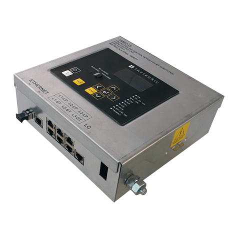
Thytronic SME2-IS User manual

SME2-IS - Manual - 06 - 2021
MANUAL
FAULT DETECTOR CONFORMING TO ENEL SPECIFICATION GSTP011 (PROTECTION AND CONTROL
DEVICE FOR MV SUBSTATION – RGDM CONTROL UNIT)

2
2SME2-IS - Manual - 06 - 2021
SUMMARYSUMMARY
1 PREFACE 5
Scope and responsibilities ............................................................................................................................................................................5
Application........................................................................................................................................................................................................5
Compliance.......................................................................................................................................................................................................5
Technical Support............................................................................................................................................................................................5
Copyright...........................................................................................................................................................................................................5
Warranty...........................................................................................................................................................................................................5
Safety instructions ..........................................................................................................................................................................................5
Isolation tests...................................................................................................................................................................................................5
Identification....................................................................................................................................................................................................5
Ambient conditions .........................................................................................................................................................................................6
Symbols.............................................................................................................................................................................................................6
Abbreviations/definitions...............................................................................................................................................................................6
2 GENERAL INFORMATION 10
Preface........................................................................................................................................................................................................... 10
Picture............................................................................................................................................................................................................ 10
Main Characteristics................................................................................................................................................................................... 10
3 TECHNICAL CHARACTERISTICS 11
3.1 GENERAL INFORMATION ................................................................................................................................................................................11
Protection and measuring relay .................................................................................................................................................................11
Mechanical characteristics........................................................................................................................................................................11
Isolation tests.................................................................................................................................................................................................11
Immunity to voltage dips..............................................................................................................................................................................11
Electromagnetic compatibility (EMC) ........................................................................................................................................................11
Issue ................................................................................................................................................................................................................12
Mechanical tests...........................................................................................................................................................................................12
Climatic conditions........................................................................................................................................................................................12
Safety instructions ........................................................................................................................................................................................12
Reference specifications.............................................................................................................................................................................12
12
Certifications................................................................................................................................................................................................. 13
3.2 INPUT CIRCUITS .............................................................................................................................................................................................. 13
Auxiliary circuit power
U
aux ....................................................................................................................................................................... 13
Combined active sensor input circuits..................................................................................................................................................... 13
Combined passive sensor input circuits .................................................................................................................................................. 13
Capacitive voltage divider input circuits.................................................................................................................................................. 13
Digital inputs ................................................................................................................................................................................................. 13
3.3 OUTPUT CIRCUITS........................................................................................................................................................................................... 13
Final relays .................................................................................................................................................................................................... 13
Current transformer..................................................................................................................................................................................... 13
3.4 MMI.....................................................................................................................................................................................................................14
3.5 COMMUNICATIONS CIRCUITS.......................................................................................................................................................................14
Local port........................................................................................................................................................................................................14
Remote connection.......................................................................................................................................................................................14
Connection to remote control peripheral..................................................................................................................................................14
3.6 BASIC PROGRAMMING ..................................................................................................................................................................................14
Nominal values..............................................................................................................................................................................................14
Cyclical input sequence...............................................................................................................................................................................14
Polarity ............................................................................................................................................................................................................14
Timers associated with the logical inputs.................................................................................................................................................15
Output relay timers........................................................................................................................................................................................15
3.7 PROTECTION FUNCTIONS..................................................................................................................................................................................15
Voltage present - RVL ...................................................................................................................................................................................15
Maximum active power directional - 32P .................................................................................................................................................15
Phase sequence control - 47.......................................................................................................................................................................15
Overcurrent - 50/51..................................................................................................................................................................................15
Residual overcurrent - 50N/51N .................................................................................................................................................................16
Ground directional overcurrent - 67N........................................................................................................................................................16
ALB frequency (automatic load balancer)................................................................................................................................................16
Second harmonic restraint - 2ndh-REST...................................................................................................................................................17
Averaged values............................................................................................................................................................................................17
THD monitoring ..............................................................................................................................................................................................17
Breaker diagnostics......................................................................................................................................................................................17

3
SME2-IS - Manual - 06- 2021
Automation functions................................................................................................................................................................................... 18
Hot Line Tag function................................................................................................................................................................................... 18
Automatic reclosing - 79 ............................................................................................................................................................................. 18
Synchrocheck relay - 25 ............................................................................................................................................................................. 18
3.8 MONITORING AND CONTROL FUNCTIONS................................................................................................................................................ 19
Oscillograph ................................................................................................................................................................................................. 19
3.9 MEASUREMENTS............................................................................................................................................................................................ 19
Measurements.............................................................................................................................................................................................. 19
Fault recording...............................................................................................................................................................................................21
Event recording.............................................................................................................................................................................................21
Measurement logging ..................................................................................................................................................................................21
GD measurement recording .......................................................................................................................................................................21
4 FUNCTIONAL CHARACTERISTICS 22
4.1 HARDWARE .......................................................................................................................................................................................................22
4.2 SOFTWARE........................................................................................................................................................................................................ 23
Basic software.............................................................................................................................................................................................. 23
Real-time operating system........................................................................................................................................................................ 23
Processes (task)........................................................................................................................................................................................... 23
Drivers............................................................................................................................................................................................................ 23
The application software ............................................................................................................................................................................ 23
Data Base...................................................................................................................................................................................................... 23
Self test (application)................................................................................................................................................................................... 23
4.3 CONFIGURATION AND CALIBRATION ..........................................................................................................................................................24
4.4 INPUTS/OUTPUTS ............................................................................................................................................................................................25
Measurement inputs.....................................................................................................................................................................................25
Measured signal processing.......................................................................................................................................................................26
Measurement conventions......................................................................................................................................................................... 29
LED signals.................................................................................................................................................................................................... 30
Communications interfaces........................................................................................................................................................................ 30
4.5 PROTECTION FUNCTIONS..................................................................................................................................................................................31
Type selection ................................................................................................................................................................................................31
4.6 PROTECTION FUNCTIONS..................................................................................................................................................................................31
Nominal values..............................................................................................................................................................................................31
Voltage present - RVL ...................................................................................................................................................................................32
Overcurrent - 50/51 .......................................................................................................................................................................................32
Residual overvoltage - 51N..........................................................................................................................................................................34
Ground directional overcurrent - 67N........................................................................................................................................................35
Directional detection of intermittent ground arcs...................................................................................................................................37
Maximum directional active power - 32P ................................................................................................................................................ 38
4.5 MONITORING AND CONTROL FUNCTIONS................................................................................................................................................ 40
ALB frequency (automatic load balancer) protection ........................................................................................................................... 40
Second harmonic restraint - 2ndh-REST...................................................................................................................................................42
Interface methods........................................................................................................................................................................................ 43
Automatic reclosing (79) ..............................................................................................................................................................................45
Hot Line Tag function....................................................................................................................................................................................47
Synchrocheck - 25 ....................................................................................................................................................................................... 48
Automatic faulty branch selection function ............................................................................................................................................ 53
GD management function............................................................................................................................................................................55
Virtual I/O........................................................................................................................................................................................................56
5 MEASUREMENTS, LOGICAL STATES AND COUNTERS 59
Protection status.......................................................................................................................................................................................... 60
Timed inputs .................................................................................................................................................................................................. 60
Automation functions................................................................................................................................................................................... 60
THD monitoring ............................................................................................................................................................................................. 60
Breaker monitoring...................................................................................................................................................................................... 60
Input function statuses.................................................................................................................................................................................61
Relays..............................................................................................................................................................................................................61
Counters..........................................................................................................................................................................................................61
Protection diagnostic status .......................................................................................................................................................................61
Selective block - BLOCKS............................................................................................................................................................................62
Virtual inputs ..................................................................................................................................................................................................62
Virtual outputs................................................................................................................................................................................................62
Fault logging - SFR ........................................................................................................................................................................................62
Event logging - SER...................................................................................................................................................................................... 63
Measurement logging ................................................................................................................................................................................. 63

4
4SME2-IS - Manual - 06 - 2021
DFR.................................................................................................................................................................................................................. 63
6 CYBER SECURITY 65
Preface............................................................................................................................................................................................................65
Configuration management ........................................................................................................................................................................65
Hardware systems and networking equipment ......................................................................................................................................65
Initial system configuration ........................................................................................................................................................................65
Threat and vulnerability management......................................................................................................................................................65
Access control..............................................................................................................................................................................................65
Authentication and authorization management......................................................................................................................................65
Auditing...........................................................................................................................................................................................................65
Network communication security..............................................................................................................................................................66
Cybersecurity application scheme.............................................................................................................................................................66
Access procedure.........................................................................................................................................................................................66
7 INSTALLATION 67
7.1 PACKAGING.......................................................................................................................................................................................................67
7.2 ASSEMBLY.........................................................................................................................................................................................................67
7.3 ELECTRICAL CONNECTIONS ......................................................................................................................................................................... 68
8 CALIBRATION AND START-UP 70
8.1 ThyVisor software............................................................................................................................................................................................ 70
Installing ThyVisor........................................................................................................................................................................................ 70
8.2 MMI (Man Machine Interface) ..................................................................................................................................................................... 70
Reading variables (READ)............................................................................................................................................................................71
Setting modifying (SET) ................................................................................................................................................................................71
Test...................................................................................................................................................................................................................72
Communication..............................................................................................................................................................................................72
CB open/close commands...........................................................................................................................................................................72
Enabling / locking the keyboard - Password........................................................................................................................................... 73
8.4 MAINTENANCE.................................................................................................................................................................................................75
8.5 REPAIRS .............................................................................................................................................................................................................75
8.6 STORAGE............................................................................................................................................................................................................75
9 APPENDIX 76
9.1 APPENDIX A - IEC time dependent curves .................................................................................................................................................76
General formula.............................................................................................................................................................................................76
First protection threshold 50/51 - IEC inverse time curves (type A, NIT).............................................................................................77
First protection threshold 50/51 - IEC very inverse time curves (type B, VIT).................................................................................... 78
First protection threshold 50/51 - IEC long inverse time curves (type LIT)......................................................................................... 79
First protection threshold 50/51 - IEC extremely inverse time curves (type C, VIT).......................................................................... 80
9.2 APPENDIX B - Insertion diagram...................................................................................................................................................................81
9.3 APPENDIX C - SME2-IS panel dimensions...................................................................................................................................................82
9.4 APPENDIX D - Revisions ................................................................................................................................................................................ 83
9.5 APPENDIX E - CE Declaration of Conformity ...............................................................................................................................................84

5
SME2-IS - Manual - 06- 2021
INTRODUCTION
1 PREFACE1 PREFACE
Scope and responsibilities
SME2-IS fault detectors are made in conformity with the ENEL GSTP011 specication (Protection
and control device for MV substation – RGDM control unit); please refer to this specication for a
full description.
This document describes the technical characteristics of the device, illustrates its operation and
gives installation, adjustment and commissioning instructions.
The content has been checked, but since we cannot exclude inaccuracies in the description, we are
not liable for errors and omissions.
The document is updated from time to time. Information about revisions is represented by the date
of publication.
We welcome any corrections and suggestions for improvement from users of the document.
Thytronic reserves the right to modify and improve the product without notifications.
Application
This document covers versions running application rmware 1.01
Compliance
The product is conforming with the following EC directives:
• EMC Directive: 2014/30/EC
• LV Directive: 2014/35/EC
Technical Support
Contacts: THYTRONIC Technical Service www.thytronic.it
Copyright
All rights reserved; documents may not be reproduced without the permission of Thytronic, nor may
the firmware and its related software be copied or modified.
Warranty
The product is covered by a one year warranty.
Safety instructions
Observe the instructions given in this document; in particular, pay special attention to the following
symbols:
Devices must be installed and commissioned by a qualied technician; Thytronic is not responsible
for any consequences of improper use or failure to observe the instructions given in this document.
In particular:
• Power the device off before working on its interior.
• Use proper instrumentation to check for voltage on all input/output terminals, with special attention
to all circuits powered externally (logical inputs, measurement inputs, etc.).
• Take care when handling metal parts (front panel, connectors).
Isolation tests
Dielectric rigidity and isolation resistance testing may generate hazardous voltages (charged capac-
itors, etc.): take care not to shut off power suddenly but gradually reduce it to zero.
Identification
• Device identication screenprinted on the front panel.
• Test label bearing the date of testing, serial number and ID of test operator.
Failure to observe these instructions can result in serious injury or death!
Failure to observe these instructions can cause damage and personal injury!
The regulations made be made following a coordination study.
The values indicated in the example calculations are purely illustrative and are not intended to be
used for the actual application.

6
6SME2-IS - Manual - 06 - 2021 INTRODUCTION
Ambient conditions
The device must be used in the environmental conditions indicated in the technical specications.
Use in other conditions requires that the device be adapted appropriately prior to commissioning
(conditioning systems, humidity control, etc.).
Appropriate filters must be installed when the device is to be used in polluted conditions (dust, cor-
rosive substances, etc.).
Symbols
The manual employs the standard CEI/IEC and ANSI symbols when available:
for example: 51 = ANSI time overcurrent relay code
This manual uses the following typographical formats:
The headings of Thyvisor[1] menus are highlighted as shown:
Overcurrent - 50/51
The descriptions of parameters (measurements, thresholds, delays, etc.) and their values are high-
lighted as follows:
Threshold I>
Time-independent
I>def
MMI display messages are highlighted with the following font:
SPR10
Notes are highlighted with cursive script on a coloured background
Note: Note considered of value to the description
Abbreviations/definitions
I
En Nominal residual current of the relay
I
Enp Nominal residual CT primary current
I
nNominal phase current of the relay
I
np Nominal CT primary phase current
25 ANSI synchrocheck relay code
27-59 ANSI undervoltage/overvoltage relay code
32P ANSI directional power code
47 Phase sequence control
50/51 ANSI overcurrent relay code
50N/51N ANSI neutral overcurrent relay code
67 ANSI directional overcurrent relay code
67 ANSI neutral directional overcurrent code
79 ANSI auto reclose code
52 or CB Circuit breaker
52a Auxiliary contact, assignable to a digital input, used to determine the
circuit breaker position for diagnostics and in case of failure to open.
The state of the contact corresponds to the circuit breaker position
(52a open = CB open)
52b Auxiliary circuit breaker contact (see 52a). The state of the contact
is opposite to the circuit breaker position (52b open = CB closed)
DFR Digital Fault Recorder (oscilloscope)
SER Sequential Event Recorder
SFR Sequential Fault Recorder
ANSI American National Standards Institute
IEEE Institute of Electrical and Electronics Engineers
IEC International Electrotechnical Commission
FSL Automatic faulty branch selection function
BLIND temporary opening inhibition signals (IEC61850)
FSL1 BLIND wait always active
FSL2 BLIND wait for rst fault occurrence only
FRT Automatic faulty branch selection function (without BLIND)
K1...K5 Output relays
PULSE Output relay programmed with a pulse output
tTR Minimum hold time with output relays tripped
CT Current transformer
P1 IEC terminology indicating the polarity of the CT primary (as an alter-
native to the ANSI dot symbol)
P2 IEC terminology indicating the polarity of the CT primary (as an alter-
native to the terminal not marked with the ANSI dot symbol)
S1 IEC terminology indicating the polarity of the CT secondary (as an
alternative to the ANSI dot symbol)
Note 1 For the detailed description of the graphic interface and use of the Thyvisor software, refer to the respective chapter

7
SME2-IS - Manual - 06- 2021
INTRODUCTION
S2 IEC terminology indicating the polarity of the CT secondary (as an
alternative to the terminal not marked with the ANSI dot symbol)
Self test Self diagnostics
Start Start of a protective function (instantaneous)
Trip Initiation of a protective function (timed)
Operating time The start and tripping time are determined by varying the input value
instantaneously (stepwise) from a set standby value to a set tripping
value.
Reset time Time required for the relay to reset, in specied conditions following
a trip, so that the successive tripping time does not differ by more
than a set percentage from the previously measured time.The reset
time is determined by changing the tripping reference value to the
reset reference value.
Overshoot time The overshoot time is determined by changing the input value instan-
taneously from the standby value to the tripping value and returning
it, again instantaneously, to the standby value. The difference be-
tween the tripping time of the test device (determined as above) and
the minimum length of the pulse which trips it is the overshoot time.
Reset ratio The ratio between the release value and the value of the same pa-
rameter that operates the device, in specied conditions. The reset
ratio may be less than or greater that 1, depending on whether the
device is an over or under voltage/current relay.
Reset delay An intentional reset delay which can be set by the user.
MMI Man Machine Interface
SW Software
FW Firmware
Thyvisor The parameter reading and setting software
Log le A text le which logs the operations of a program (Thyvisor)
Upgrade Firmware update
XML EXtensible Markup Language

8
8SME2-IS - Manual - 06 - 2021 INTRODUCTION
Symbols.ai
Symbols
Internal logical signal (output); may be a logical state (e.g. U>> Start) or a numerical value
The variable is available in read (ThyVisor + communications interfaces)
External logical signal (input); may be a digital input command or an SW command
The variable is available in read (ThyVisor + communications interfaces)
Internal signal (e.g. state of the Breaker Failure signal relative to the second threshold of function 50)
The variable is not available in read (non-availability is indicated by the lack of an arrow)
AND and NAND logical ports
OR and NOR logical ports
Comparator block (e.g. tripping threshold U>>)
Calculation block (e.g. maximum phase current value)
Regulation (e.g. tripping threshold I>>)
The variable is available in read and can be set with ThyVisor + MMI
Commutator
Resettable timer with tripping delay
(tripping time tON)
Non-resettable timer with tripping delay
(tripping time tON)
Non-resettable timer with reset delay
(reset time tOFF)
Tripping characteristic (dependent/independent)
&
≥1
EXOR logical port

9
SME2-IS - Manual - 06- 2021
INTRODUCTION
Symbols1.ai
tOFF
Minimum tripping time for output relays (tTR)tTR
t
tTR
INPUT
OUTPUT
tTR
0 T
tTR
t
tTR
INPUT
OUTPUT
Latched operating mode of output relays and
LEDs
Pulse operating mode of output relays
t
INPUT
OUTPUT
Latched
tTR
T0
RESET
Resettable timer with reset delay
(reset time tOFF)
t
RESET
INPUT
OUTPUT
tOFF
tOFF
tOFF

10
10 SME2-IS - Manual - 06 - 2021 GENERAL INFORMATION
2 GENERAL INFORMATION2 GENERAL INFORMATION
Preface
SME2-IS fault detectors are conforming with ENEL specication GSTP011 (Protection and control
device for MV substation – RGDM control unit); they are installed in remote controlled substations
to detect phase faults and ground faults on both isolated neutral grids and compensated neutral
grids, without the need for modication to handle switching between the two grid congurations and
independently of the power direction;
In particular:
• they detect multi-phase faults and single-phase ground faults,
• they detect line undervoltage,
• they measure the voltage and the active and reactive power of the MV line,
• the open and close the DY800 in response to faults or when remotely operated by UP,
• they interface with the generators on the MV grid to coordinate the regulation of the voltage along
the line and remote disconnection signals.
The input circuits are suited to acquire measurements with integrated phase current/voltage sen-
sors; the device is able, with SW selection, to acquire the current values from active sensors (signal
proportional to the current transduced by the sensor) or passive sensors (DJ 5400 and GSTC005 -
signal proportional to the value of the time derivative of the current), and can measure current and
voltage values with IEC 61869-10 and IEC 61869-11 low power sensors.
The homopolar values are calculated vectorially from the measured phase currents and voltages.
Voltage measurement inputs are available with capacitive voltage dividers.
Two Ethernet communications ports are available, of which one runs the IEC61850 protocol.
To ensure full compatibility with any RTUs already on the secondary systems, the SME2-IS device
is equipped with a dual interface to dialogue with both the UP (DX1215) and future communications
equipment.
The system can be calibrated, programmed and its logs and values read with a PC, or via the Ether-
net communications port using the freely available ThySetter software; all the above operations are
also available via the front panel keypad (MMI).
Picture
Main Characteristics
• Metal enclosure
• Backlit LCD display
• Ten indicator LEDs on the front panel, freely programmable
• RESET button for resetting the indicators
• Switch open/close buttons
• Hot Line Tag function button
• Switch for enabling/disabling auto-reclose

11
SME2-IS - Manual - 06- 2021
TECHNICAL CHARACTERISTICS
3 TECHNICAL CHARACTERISTICS3 TECHNICAL CHARACTERISTICS
3.1 GENERAL INFORMATION
Protection and measuring relay
Reference standards IEC 60255-1 Part 1: Common requisites
Mechanical characteristics
Mounting protruding
Dimensions (H x W x D) 210 x 200 x 72
Terminals screw clamps
Weight 1.7 kg
Isolation tests
Standards EN 60255-5, IEC 60255-27
Test at 50 Hz (1 min):
• Auxiliary circuit 2 kV
• Input circuits 2 kV
• Output circuits 2 kV
• Output circuits (between open contacts) 1 kV
• Ethernet copper (Tx) 1 kV
Pulse test (1.2/50 µs):
• Auxiliary power circuit 5 kV (common mode) - 2 kV (differential mode)
• Input circuits 5 kV (common mode) - 2 kV (differential mode)
• Output circuits 5 kV (common mode) - 2 kV (differential mode)
• Output circuits (between open contacts) 2 kV
Isolation resistance >100 MW
Immunity to voltage dips
Reference standards EN 61000-4-29, IEC 61000-4-11
Immunity to voltage dips, brief interruptions and voltage variations on DC power ports
• Voltage dip duration with UT=50% 100 ms
• Short interruption duration with UT=0% 50 ms
• Voltage variation duration with Un=80...120% 10 s
Electromagnetic compatibility (EMC)
Reference standards EN 60255-26, IEC 60255-26
Electromagnetic compatibility requisites for measuring relays and protection equipment
General immunity standard EN 61000-6-2
Automation and control equipment for electrical power stations and substations
• Electromagnetic compatibility - Immunity ENEL REMC 02
• Electromechanical compatibility regulations for equipment and systems
ENEL REMC 01
Reference standards EN 60255-22-1, IEC 60255-22-1
EN 61000-4-18 IEC 61000-4-18
Damped oscillatory wave
• 0.1 MHz and 1 MHz common mode 1.0 kV
• 0.1 MHz and 1 MHz differential mode 0.5 kV
Reference standards EN 60255-22-1, IEC 60255-22-1
EN 61000-4-12 IEC 61000-4-12
Ring Wave
• Ring wave common mode 2.0 kV
• Ring wave differential mode 1.0 kV
Reference standards EN 60255-22-2, IEC 60255-22-2
EN 61000-4-2 IEC 61000-4-2
Electrostatic discharge
• Contact discharge 6 kV
• Air discharge 8 kV
Reference standards EN 60255-22-3, IEC 60255-22-3
EN 61000-4-3 IEC 61000-4-3
Radiated electromagnetic fields
• 80...2700 MHz AM 80% 10 V/m
• 900 MHz pulse modulated 10 V/m
Reference standards EN 60255-22-4 IEC 60255-22-4
EN 61000-4-4 IEC 61000-4-4

12
12 SME2-IS - Manual - 06 - 2021 TECHNICAL CHARACTERISTICS
Tests for immunity to fast electrical transients/pulse trains (5/50 ns)
• All the circuits 4 kV
Reference standards EN 60255-22-5, IEC 60255-22-5
EN 61000-4-5 IEC 61000-4-5
High energy pulses
• Uaux common mode 2 kV
• Uaux differential mode 1 kV
Reference standards EN 60255-22-6, IEC 60255-22-6
EN 61000-4-6 IEC 61000-4-6
Conducted electromagnetic fields
• 0.15...80 MHz AM 80% 1kHz 10 V
Reference standards EN 60255-22-7, IEC 60255-22-7
EN 61000-4-16 IEC 61000-4-16
Mains frequency voltage
• Direct current 100 V
• 50 Hz continuous 100 V
• 50 Hz 1 s 300 V
• 0.015...150 kHz 10 -1 -1 10 V
Reference standards EN 61000-4-8, IEC 61000-4-8
50 Hz magnetic field
• 50 Hz continuous 100 A/m
• 50 Hz 1 s 1 kA/m
Reference standards EN 61000-4-10, IEC 61000-4-10
Damped oscillatory wave magnetic field
• Damped oscillatory wave 0.1 MHz 30 A/m
• Damped oscillatory wave 1 MHz 30 A/m
Issue
Reference standard IEC 60255-26
EN 60255-25 IEC 60255-25
EN 61000-6-4 IEC 61000-6-4
EN 55011 CISPR 32
Electromagnetic emissions
• Auxiliary power conducted emission 0.15...0.5 MHz 79 dB mV
• Auxiliary power conducted emission 0.5...30 MHz 73 dB mV
• Radiated emission 30...230 MHz 40 dB mV/m
• Radiated emission 230...1000 MHz 47 dB mV/m
Mechanical tests
Reference standard EN 60255-21-1 EN 60255-21-2 RMEC01
Vibration, impact, shock and seismic resistance tests for measurement relays and protection
equipment
• EN 60255-21-1 Vibration tests (sinusoidal) Class 1
• EN 60255-21-2 Impact and shock tests Class 1
• EN 60068-2-64 Wide band random vibration Class 1
Climatic conditions
Reference standard IEC 60068-x ENEL R CLI 01 CEI 50
Environmental tests
Ambient temperature -25...+70 °C
Storage temperature -40...+85 °C
Relative humidity 10...95 %
Atmospheric pressure 70...110 kPa
Safety instructions
Reference standard IEC 60255-27
Pollution degree 3
Reference voltage 250 V
Reference category III
Reference specifications
Directional fault detector and measuring relay RGDM ST Prescriptions and test methods
ENEL GSTP011 Ver. 01 (26/07/2019)
ENEL GSTP012 Ver. 01 (26/07/2019)
ENEL GSTP013 Ver. 01 (26/07/2019)
ENEL GSTP901 Ver. 01 (06/12/2018)
Smart Termination ENEL DJ5400 - ENEL GSCT0051

13
SME2-IS - Manual - 06- 2021
TECHNICAL CHARACTERISTICS
Certifications
Reference standards EN 50263
CE conformity
• EMC Directive 2014/30/EC
• Low Voltage Directive 2014/35/EC
Type testing IEC 60255-1
3.2 INPUT CIRCUITS
Auxiliary circuit power
U
aux
Voltage
• Nominal value (range) 24 V-
• Operating range 19...29 V-
Max. time to full operation 15 s
Max power draw 14 W
Combined active sensor input circuits
Nominal frequency fn50 or 60 Hz
15.5 mV
Secondary nominal voltage (I direct - Inp = 500 A)
{
50 mV
150 mV
Secondary nominal voltage (with Unp = 10 kV) 1.0 V
Connections RJ45 socket
Combined passive sensor input circuits
Reference standards ENEL GSCT005
Nominal frequency fn50 or 60 Hz
15.5 mV
Secondary nominal voltage (I derivative - Inp = 500 A)
{
50 mV
150 mV
Secondary nominal voltage (with Unp = 10 kV) 1.0 V
Connections RJ45 socket
Capacitive voltage divider input circuits
Reference standards ENEL DY1811
MV line nominal secondary voltage 6 ... 24 kV
MV side capacitive reactance 100...700 MΩ
Digital inputs
Number of inputs: 6
Circuit type: photocoupler
Range nominal range Uaux
Maximum current draw with excited input 3 mA
3.3 OUTPUT CIRCUITS
Final relays
Number 5
Signalling (K1...K3)
Contact type: Closing (SPST-NO, type A)
Nominal current 2 A
Nominal voltage 250 V
Interrupting capacity, DC (24 V, L/R = 40 ms) 0.2 A
Minimum switchable load 300 mW (5 V/ 5 mA)
Breaker command (K4, K5)
Contact type closing (SPST-NO, type A)
Nominal current 8 A
Nominal voltage / maximum switchable voltage 250 VAC/400 VAC
Interrupting capacity:
• DC (L/R = 40 ms) 50 W
• AC (λ= 0.4) 1250 VA
• Closing power (Make) 1000 W/VA
Maximum instantaneous current (0.5 s) 30 A
Current transformer
Measurements:
• Current 4-20 mA
• Voltage (xx...xx kV primary) 4-20 mA
• Positive active power (xx...xx kW primary) 12-20 mA
• Negative active power (xx...xx kW primary) 4-12 mA
• Positive reactive power (xx...xx kVAR primari) 12-20 mA
• Negative reactive power (xx...xx kVAR primari) 4-12 mA

14
14 SME2-IS - Manual - 06 - 2021 TECHNICAL CHARACTERISTICS
Sampling 200 ms
Partial average calculation period 60 s
Nominal multiplier (DACMUL) 0.01...2.00
3.4 MMI
Display backlit graphic LCD
LEDs
Number 10
• ON/fail green
• V4-V8-V12 green
• Function 51 - 51N red
• Function 67N red
• Function 32P red
• Inversion (INV) green
• Re-closing cycle in progress (CRC) yellow
• Control input (LOCAL) green
• Hot Line Tag red
• Fault red
Keypad 9 buttons
3.5 COMMUNICATIONS CIRCUITS
Local port
Ethernet 100 Tx 100 Mbps
Connection RJ45
Protocol ModBus TCP/IP
Remote connection
Ethernet 100 Fx 100 Mbps
• Connection Optical bre
• Protocol IEC61850 level A
Connection to remote control peripheral
Type Multipole 9 wire cable
• Section 1 mm2
• Length 9 m
3.6 BASIC PROGRAMMING
Nominal values
RGDM
Device conguration BASIC, EXTENDED
Automation function selected FSL1, FSL2, FRT
Nominal frequency of relay (fn) 50, 60 Hz
Nominal primary current of phase sensors (Inp) 500 A
Nominal phase voltage of relay (En) Un/√3
Nominal primary phase-to-phase voltage (Unp) 6 ...... 36 kV, 400 V
Nominal residual voltage of relay (calculated) (UECn) Un· √3 = En· 3
Nominal active power Pn = √3UnIn = 3EnIn
Nominal reactive power Qn = √3UnIn = 3EnIn
Nominal apparent power Sn = √3UnIn = 3EnIn
RGDAT
Nominal frequency of relay (fn) 50, 60 Hz
Nominal primary current of phase sensors (Inp) 500 A
Nominal phase voltage of relay (En) Un/√3
Nominal primary phase-to-phase voltage (Unp) 6 ...... 36 kV
Nominal residual voltage of relay (calculated) (UECn) Un· √3 = En· 3
Nominal active power Pn = √3UnIn = 3EnIn
Nominal reactive power Qn = √3UnIn = 3EnIn
Nominal apparent power Sn = √3UnIn = 3EnIn
Cyclical input sequence
Cyclical sequence of phase currents (I-Sequence) IL1-IL2-IL3,....
Cyclical sequence of phase voltages (V-Sequence) UL1-UL2-UL3, UL1-UL3-UL2....
Polarity
Polarity I-L1 (I-L1 POL) NORMAL/INVERTED
Polarity I-L2 (I-L2 POL) NORMAL/INVERTED

15
SME2-IS - Manual - 06- 2021
TECHNICAL CHARACTERISTICS
Polarity I-L3 (I-L3 POL) NORMAL/INVERTED
Polarity U-L1 (U-L1 POL) NORMAL/INVERTED
Polarity U-L2 (U-L2 POL) NORMAL/INVERTED
Polarity U-L3 (U-L3 POL) NORMAL/INVERTED
Timers associated with the logical inputs
Logic POSITIVE/NEGATIVE
OFF/ON acquisition delay (IN1 tON,... IN6 tON) 0.00...100.0 s
ON/OFF acquisition delay (IN1 tOFF,... IN6 tOFF) 0.00...100.0 s
Output relay timers
Minimum pulse length 0.000...0.500 s
3.7 PROTECTION FUNCTIONS
Voltage present - RVL
Threshold UL>
• Threshold (UL>) 0.50...1.10 En
• Intentional delay (tUL>) 0.03...10.00 s
Threshold UL<
• Threshold (UL<) 0.10...0.40 En
• Intentional delay (tUL<) 0.03...10.00 s
Maximum active power directional - 32P
Threshold P>
Tripping reference (P>rif) Positive/Negative/Modulo
Operating mode (P>Mode) Mode-a,Mode-B, Mode-c
Trip to OdM delay (todMSc) 10...60 s
Reset delay (tP>RES) 0.00...100.0 s
Time-independent
• Threshold (P>) 0.0100...1.0000 Pn
• Tripping time (tP>) 0.05...10.00 s
Phase sequence control - 47
Time-independent
• Threshold (Us1<) 0.05...0.30 En
• Threshold (Us>) 0.70...1.00 U
Overcurrent - 50/51
Common congurations:
• Operating mode (Mode51) I/I*cos
• Operating logic (Logic51) 1/3, 2/3
Threshold I>
• Directionality (I> Dir) Directional, Non directional
• Characteristic type (I>Curve) NIT (Normal inverse time), VIT (Very inverse time),
EIT (Extremely inverse time), LIT (Long inverse time)
• Reset delay (t>RES)0.00...100.0 s
• Second harmonic restraint (I>2ndh-REST)ON/OFF
Time-dependent
• First time-dependent threshold (I>inv) 0.02...0.40 In
• Characteristic angle (ThetaPI> inv) 0...359 °
• Tripping time (t>inv) 0.02...60.0 s
• Tripping sector (Beta I >) 0...90 °
Threshold I>>
• Directionality (I>> Dir) Directional, Non directional
• Reset delay (t>>RES)0.00...100.0 s
• Second harmonic restraint (I>>2ndh-REST)ON/OFF
Time-independent
• First time-independent threshold (I>>def) 0.02...3.00 In
• Characteristic angle (ThetaP>>def) 0...359 °
• Tripping time (t>>def) 0.05...200 s
• Tripping sector (Beta I >>) 0...90 °
Threshold I>>>
• Directionality (I>>> Dir) Directional, Non directional
• Reset delay (t>>>RES)0.00...100.0 s
• Second harmonic restraint (I>>>2ndh-REST)
ON/OFF
Time-independent
• Third time-independent threshold 51 (I>>>def) 0.02...3.00 In
• Characteristic angle (ThetaP>>>def) 0...359 °
• Tripping time (t>>>def) 0.05...10.00 s
• Tripping sector (Beta I >>>) 0...90 °

16
16 SME2-IS - Manual - 06 - 2021 TECHNICAL CHARACTERISTICS
Threshold I>>>>
• Directionality (I>>>> Dir) Directional, Non directional
• Reset delay (t>>>>RES)
0.00...100.0 s
• Second harmonic restraint (I>>>>2ndh-REST)ON/OFF
Time-independent
• Fourth time-independent threshold (I>>>>def) 0.02...3.00 In
• Characteristic angle (ThetaP>>>>def) 0...359 °
• Tripping time (t>>>>def) 0.05...10.00 s
• Tripping sector (Beta I >>>>) 0...90 °
Residual overcurrent - 50N/51N
Threshold IE>
• Reset delay (tE>RES) 0.00...100.0 s
• Second harmonic restraint (IE>2ndh-REST)
ON/OFF
Time-independent
• First time-independent threshold (
I
E>def) 0.010...2,000 IEn
• Tripping time (tE>def) 0.05...30.0 s
Threshold IE>>
• Reset delay (tE>>RES) 0.00...100.0 s
• Second harmonic restraint (IE>>2ndh-REST)
ON/OFF
Time-independent
• Second time-independent threshold (
I
E>>def) 0.010...2.000 IEn
• Tripping time (tE>>def) 0.05...10.00 s
Ground directional overcurrent - 67N
Threshold IED>
• Reset delay (tED>RES) 0.00...100.0 s
Time-independent
First time-independent threshold (IED>def - UED>def)
• Residual current tripping time 0.002...0.032 In
• Residual voltage tripping value 0.010...1.000 UEn
• Characteristic angle 0...359°
• Tripping half-sector 1...180°
• Tripping time (tED>def) 0.05...30.0 s
Threshold IED>>
• Reset delay (tED>>RES) 0.00...100.0 s
Time-independent
Second time-independent threshold (IED>>def - UED>>def)
• Residual current tripping time 0.002...0.032 In
• Residual voltage tripping value 0.010...1.000 UEn
• Characteristic angle 0...359°
• Tripping half-sector 1...180°
• Tripping time (tED>>def) 0.05...15.0 s
Threshold IED>>>
• Reset delay (tED>>>RES) 0.00...100.0 s
Time-independent
Third time-independent threshold (IED>>>def - UED>>>def)
• Residual current tripping time 0.002...1.000 In
• Residual voltage tripping value 0.010...1.000 UEn
• Characteristic angle 0...359°
• Tripping half-sector 1...180°
• Tripping time (tED>>>def) 0.05...1.00 s
Threshold IED>>>>
• Reset delay (tED>>>RES) 0.00...100.0 s
Time-independent
• Tripping time (tED>>>>def) 0.50...2.00 s
ALB frequency (automatic load balancer)
Block thresholds
Minimum voltage Ueac<def 0.05 ...1.40 En ( step 0.05 En)
Tripping time tUeac< 0.05 ...9.99 s (step 0.01 s)
10.0 .. 99.9 s (step 0.1 s)
100 ...1000 s (step 1 s)
Maximum voltage Ueac>def 0.05 ...1.40 En ( step 0.05 En)
Tripping time tUeac> 0.05 ...9.99 s (step 0.01 s)
10.0 .. 99.9 s (step 0.1 s)
100 ...1000 s (step 1 s)
Maximum unbalance ULS>def 0.05 ...1.00 Um ( step 0.05 Um)
Reset delay tULS>RES 0.00 ...9.99 s (step 0.01 s)
10.0 .. 100.0 s (step 0.1 s)
Tripping time tULS> 0.05 ...9.99 s (step 0.01 s)
10.0 .. 99.9 s (step 0.1 s)

17
SME2-IS - Manual - 06- 2021
TECHNICAL CHARACTERISTICS
100 ...1000 s (step 1 s)
Maximum frequency difference UG>def 10 ...200 mHz (step 1 mHz)
Reset delay tUG>RES 0.00 ...9.99 s (step 0.01 s)
10.0 .. 100.0 s (step 0.1 s)
Tripping time tUG> 0.05 ...9.99 s (step 0.01 s)
10.0 .. 99.9 s (step 0.1 s)
100 ...1000 s (step 1 s)
Maximum active return power P-> -1.00 ...-0.01 Pn (step 0.01 Pn)
Reset delay tP->RES 0.00 ...9.99 s (step 0.01 s)
10.0 .. 100.0 s (step 0.1 s)
Tripping time tP-> 0.05 ...9.99 s (step 0.01 s)
10.0 .. 99.9 s (step 0.1 s)
100 ...1000 s (step 1 s)
Maximum variation in consecutive periods UDT> 50 ...7000 us (step 10 us)
Calculated means of f and df
Number of mean frequency semi-periods 1 ... 32 (step 1)
Number of rst scale df/dt calculation semi-periods (0.1÷0.9 Hz/s) 0 ... 20 (step 1)
Number of second scale df/dt calculation semi-periods (1÷4.9 Hz/s) 0 ... 20 (step 1)
Number of third scale df/dt calculation semi-periods (5÷10 Hz/s) 0 ... 20 (step 1)
Number of rst scale df/dt calculation means (0.1÷0.9 Hz/s) Means (1, 2, 4, 8, 10, 12, 14, 16, 18, 20)
Number of second scale df/dt calculation means (1÷4.9 Hz/s) Means (1, 2, 4, 8, 10, 12, 14, 16, 18, 20)
Number of third scale df/dt calculation means (5÷10 Hz/s) Means (1, 2, 4, 8, 10, 12, 14, 16, 18, 20)
Threshold EAC1
Type f>/f<1a Maximum/Minimum
Threshold f>/f<1a 45.00 ... 55.00 Hz (step 0.01 Hz)
Tripping time tf>/f<1a 0.00 ... 60.00 s (step 0.01 s)
Type f>/f<1b Maximum/Minimum
Threshold f>/f<1b 45.00 ... 55.00 Hz (step 0.01 Hz)
Tripping time tf>/f<1b 0.00 ... 60.00 s (step 0.01 s)
Threshold df>1 0.1 ... 10.00 Hz/s (step 0.1 Hz/s)
Tripping time tdf>1 0.00 ... 60.00 s (step 0.01 s)
Threshold EAC2
Type f>/f<2a Maximum/Minimum
Threshold f>/f<2a 45.00 ... 55.00 Hz (step 0.01 Hz)
Tripping time tf>/f<2a 0.00 ... 60.00 s (step 0.01 s)
Type f>/f<2b Maximum/Minimum
Threshold f>/f<2b 45.00 ... 55.00 Hz (step 0.01 Hz)
Tripping time tf>/f<2b 0.00 ... 60.00 s (step 0.01 s)
Threshold df>2 0.1 ... 10.00 Hz/s (step 0.1 Hz/s)
Tripping time tdf>2 0.00 ... 60.00 s (step 0.01 s)
Second harmonic restraint - 2ndh-REST
Second harmonic restraint threshold (I2ndh>) 10...50 %
Reset delay (t2ndh>RES) 0.00...100.0 s
Intentional delay (t2ndH-REST) 0.05...3.00 s
Averaged values
Fixed average period (tFIX) 1...60 min
Moving average period (tROL) 1...60 min
Periods per moving average (N.ROL) 1...24
THD monitoring
Threshold (THDI>) 6...12 %
Intentional delay (tTHD-I>) 1...15 min
Threshold (THDU>) 6...12 %
Intentional delay (tTHD-U>) 1...15 min
Breaker diagnostics
Opening counter threshold (N.Open) 0...10000
Interrupted current sum threshold (SumI) 0...5000 In
Opening time for calculation ∑I2t (tbreak) 0.05...1.00 s
Interrupted I^2t sum threshold (SumI^2t) 0...5000 In2.s
Maximum admitted opening time (tbreak>) 0.05...1.00 s

18
18 SME2-IS - Manual - 06 - 2021 TECHNICAL CHARACTERISTICS
Automation functions
Function selection for BLIND reception (FSL SelBlindIn) I>>, I>>>, I>>>>, IED>, IED>>,
IED>>>, ∑IED>>>>, IE>, IE>>
Function selection for BLIND emission (FSL SelBlindOut) I>>, I>>>, I>>>>, IED>, IED>>,
IED>>>, IED>>>>, IE>, IE>>
BLIND wait time (tFSL-Att) 0.000...0.500 s
BLIND additional time (tFSL-Add) 0.000...0.100 s
BLIND delay time (tFSL-Tr) 0.000...0.500 s
Selectivity failure time (tFSL-RGFake) 0.000...0.500 s
Tripping memorisation time with TS PRES V failure (tFSL-RGD) 0.000...0.500 s
Blind to UP time (tFSL-RVUP) 60...300 s
Hot Line Tag function
Function enable HLT button
Automatic reclosing - 79
Re-closing cycle type (79 Type) Complete/Standard
Line type (79 LineType) Mixed/Cable
Reclosing program (79 Mode) Rapid/Rapid+Slow
Number of memorised reclosings (N.DAR) 0...5
Rapid wait (trdt)0.10...1.00 s
Slow wait (tsdt)1...200 s
Neutralisation time (tr)1...200 s
Automation end time (tfa)1...360 min
Discrimination time from slow mixed line request (td1-mista)0...10 s
Discrimination time from slow cable line request (td1-cavo)0...10 s
Discrimination time from memorized re-closing (td2)0...10 s
Re-closing trigger I>>, I>>>, I>>>>, IE>, IE>>. IED>,
IED>>, IED>>>, IED>>>>, 51A, 67A
Synchrocheck relay - 25
Common congurations:
• Minimum stabilisation time (tSTAB) 0.10...10.00 s
• Breaker closing time (tCB-CLOSE) 0.02...0.20 s
• Synchrocheck timeout (timeout-SYNC) 1...20 min
• Synchronisation emission delay (tSYNC) 0.00...60.0 s
• Upper voltage limit threshold (Vmax-SYNC) 0.50...1.50 En
• Lower voltage limit threshold (Vmin-SYNC) 0.20...1.50 En
• Permitted frequency range for V1, V2 (fRANGE) fn ±0.5...3.0 Hz
• Frequency measurement repeatability (Rof>SYNC) 0.00...0.60 Hz
Parameters:
• Synchronism/asynchronism threshold (df-GRID) 0.01...0.10 Hz
• Frequency difference with f1>f2 (df12-SYNC) 0.02...1.00 Hz
• Frequency difference with f2>f1 (df21-SYNC) 0.02...1.00 Hz
• Voltage difference with V1>V2 (dV12-SYNC) 0.01...0.40 En
• Voltage difference with V2>V1 (dV21-SYNC) 0.01...0.40 En
• Phase difference with V2 in advance of V1 (dp12-SYNC) 1...60°
• Phase difference with V2 behind V1 (dp21-SYNC) 1...60°
• No voltage threshold V1 (V1<SYNC) 0.05...0.60 En
• No voltage threshold V2 (V2<SYNC) 0.05...0.60 En
• Minimum no voltage time V1 (tV1<SYNC) 0.00...10.0 s
• Minimum no voltage time V2 (tV2<SYNC) 0.00...10.0 s

19
SME2-IS - Manual - 06- 2021
TECHNICAL CHARACTERISTICS
3.8 MONITORING AND CONTROL FUNCTIONS
Oscillograph [1]
Format COMTRADE
Recording method cyclic
Sampling frequency 32 samples per period
Trigger settings:
• Pre-trigger time 0.05...1.00 s (step 0.01 s)
• Post-trigger time 0.05...60.00 s (step 0.01 s)
• Output triggers K1...K5
• Input triggers IN1...IN6
• Manual control Thyvisor, remote control
Sampled channel settings:
• Instantaneous currents iL1, iL2, iL3, iE
• Instantaneous phase voltages uL1, uL2, uL3, uE
Measurement channel settings
(Analogue 1...12):
• Frequency f
• Phase currents IL1, IL2, IL3
• Calculated residual current IE
• Phase voltages UL1, UL2, UL3
• Calculated residual voltage UE
• Phase-to-phase voltages U12, U23, U31
• Phase shift (IL1-UL1, IL2-UL2, IL3-UL3) PhiL1, PhiL2, PhiL3
• Phase shift (IL1-U23, IL2-U31, IL3-UL3) Alpha1, Alpha2, Alpha3
• Phase shift (UE-IE) PhiE
• Forward and reverse sequence voltage U1, U2
• Phase current second harmonic IL1-2nd, IL2-2nd, IL3-2nd
• Percentage ratio of phase current second harmonic/fundamental component
(I-2nd /IL)
Digital channel settings (Digital 1...12):
• Input status UD, RVS, Anin, caX89, ccX89
• Output status K1...K5
3.9 MEASUREMENTS
Measurements
Sampling frequency 256 s/p
Direct
RMS fundamental phase currents IL1, IL2, IL3
RMS fundamental phase voltages UL1, UL2, UL3
RMS fundamental residual current IE
RMS fundamental residual voltage UE
Capacitive voltage divider voltage V2
67N measurements
Residual current IE
Residual voltage UE
Phase shift of IErelative to UEPhiE
Calculated
Phase-to-phase voltages U12, U23, U31
Maximum current between IL1-IL2-IL3 ILmax
Minimum current between IL1-IL2-IL3 ILmin
Mean current between IL1-IL2-IL3 IL
Maximum voltage between UL1-UL2-UL3 ULmax
Mean voltage between UL1-UL2-UL3 UL
Maximum voltage between U12-U23-U31 Umax
Mean voltage between U12-U23-U31 U
Phase shift measurements
Phase shift of IL1 relative to UL1 PhiL1
Phase shift of IL2 relative to UL2 PhiL2
Phase shift of IL3 relative to UL3 PhiL3
Phase shift of IL1 relative to U23 Alpha1
Phase shift of IL2 relative to U31 Alpha2
Phase shift of IL3 relative to U12 Alpha3
Phase shift of UErelative to IEPhiE
Sequences
Direct sequence voltage U1
Reverse sequence voltage U2
Note 1 This function requires a license, contact Thytronic to purchase it

20
20 SME2-IS - Manual - 06 - 2021 TECHNICAL CHARACTERISTICS
Power measurements
Total active power P
Total reactive power Q
Total apparent power S
Power factor CosPhi
Second harmonic
Phase current second harmonic (IL1-2nd, IL2-2nd, IL3-2nd)
Maximum percentage ratio of phase current second harmonic/fundamental component
(I-2nd /IL)
3rd harmonic measurements
Phase current third harmonic IL1-3rd, IL2-3rd, IL3-3rd
4th harmonic measurements
Phase current fourth harmonic IL1-4th, IL2-4th, IL3-4th
5th harmonic measurements
Phase current fth harmonic IL1-5th, IL2-5th, IL3-5th
Average phase currents
Fixed mean phase currents IL1FIX, IL2FIX, IL3FIX
Mobile mean phase currents IL1ROL, IL2ROL, IL3ROL
Phase overcurrents IL1MAX, IL2MAX, IL3MAX
Minimum phase currents IL1MIN, IL2MIN, IL3MIN
Average phase-to-phase voltages
Fixed mean phase-to-phase voltages U12FIX, U23FIX, U31FIX
Mobile mean phase-to-phase voltages U12ROL, U23ROL, U31ROL
Maximum phase-to-phase voltages U12MAX, U23MAX, U31MAX
Minimum phase-to-phase voltages U12MIN, U23MIN, U31MIN
Average measures at 10 s
10 s mean phase currents IL1IST, IL2IST, IL3IST
10 s mean phase-to-phase voltages U12IST, U23IST, U31IST
10 s mean active power PIST
10 s mean reactive power QIST
10 s mean THD of current IL3 THD-IL3IST
10 s mean THD of UL3 THD-UL3IST
Total harmonic distortion[1]
THD of phase current L3 IL3 - THD
THD of phase voltage L3 UL3 - THD
Average total harmonic distortion measures [1]
Fixed mean THD of phase current L3 THDIL3FIX
Fixed mean THD of phase voltage L3 THDUL3FIX
Mobile mean THD of phase current L3 THDIL3ROL
Mobile mean THD of phase voltage L3 THDUL3ROL
Maximum THD of phase current L3 THDIL3MAX
Maximum THD of phase voltage L3 THDUL3MAX
Minimum THD of phase current L3 THDIL3MIN
Minimum THD of phase voltage L3 THDUL3MIN
Note 1 The calculation considers the contribution of harmonics up to the 25th order
Average power measures
Fixed mean active power PFIX
Fixed mean reactive power QFIX
Mobile mean active power PROL
Mobile mean reactive power QROL
Maximum active power PMAX
Maximum reactive power QMAX
Minimum active power PMIN
Minimum reactive power QMIN
Other manuals for SME2-IS
1
Table of contents
Other Thytronic Security Sensor manuals
Popular Security Sensor manuals by other brands

Honeywell
Honeywell Miller MightyLite Series User instruction manual supplement
SAFERA
SAFERA Aurora user manual
SILENTRON
SILENTRON 5514 SILENT Dual Tech manual
IFM Electronic
IFM Electronic efector150 operating instructions
Jung
Jung BM360MBWW operating instructions
Sinfonia Technology
Sinfonia Technology EA-15B quick start guide
