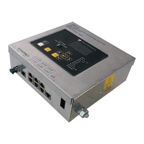
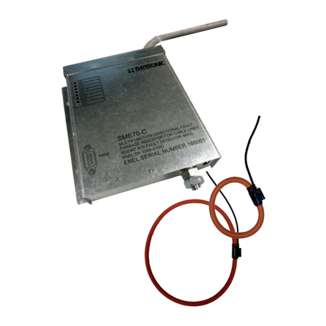
Thytronic SME70-O User manual

SME70-O-Manual-04-2020
SME70-O
FAULT DETECTOR
MANUAL
SME70
27V1 59 59V2 59N
51
67N
SME70
27V1 59 59V2 59N
51
67N
SME70
27V1 59 59V2 59N
51
67N

2SME70-O-Manual-04-2020
INTRODUCTION
—Scope and liability
The functions, technical data, instructions for setting and commissioning of SME70-O devices are
explained.
This manual has been checked out, however, deviations from the description cannot be completely
ruled out, so that no liability in a legal sense for correctness and completeness of the information or
from any damage that might result from its use is formally disclaimed.
The information given in this document is reviewed regularly; any corrections and integration will be
included in subsequent editions that are identified by the date of revision.
We appreciate any suggestions for improvement.
We reserve the right to make technical improvements without notice.
—Applicability
This manual is valid for SME70-O devices with firmware version 1.00 and following.
—Conformity
The product complies with the CEE directives:
• EMC Council Directives 2014/30/EC
• Low voltage Directives: 2014/35/EC
• GICT-SGL_12_v01_OCS OT Security Guideline
—Technical support
Contact: THYTRONIC Technical Service www.thytronic.it
—Copyright
All right reserved; It is forbidden to copy, modify or store material (document and sw) protected by
copyright without Thytronic consent.
—Warranty
Thytronic warrants devices against defects in materials and workmanship under normal use for a
period of ONE (1) YEAR from the date of retail purchase by the original end-user purchaser (“War-
ranty Period”).
—Safety recommendations
The warming contained in this document are all-important for safety; special attention must be paid
to the following symbols:
Installation and commissioning must be carried out by qualified person; Thytronic assumes no re-
sponsibility for damages caused from improper use that does not comply all warning and caution in
this manual.
In particular the following requirements must be met:
• Remove power before opening it.
• Verify the voltage absence by means suitable instrumentation on relay connections; attention must
be paid to all circuits supplied by external sources (binary input, analog inputs, etc...)
• Care must be taken when handling metal parts (front panel, connectors).
—Insulation tests
After insulation tests, hazardous voltages (capacitor charges,...) may be arise; it is advisable to grad-
ually reduce the test voltage avoiding to erase it abruptly.
WARNING Death, severe personal injury or substantial property damage can result if proper precautions
are not taken.
CAUTION Minor personal injury or property damage can result if proper precautions are not taken

3
SME70-O-Manual-04-2020
G E N E R A L
—Relay typology
SME70-OSuitable to install on MV cable lines connected outdoor RGDAT sensors.
The supplied devices are:
• SME70
• CVS-P-24-O RGDAT sensors
• Cable for UP connection
• Support shelf for sensors
• Junction box
• Fixing bracket for junction box
• Corrugated tube
—General info
SME70-O fault detection system is designed in conformity with the ENEL GSTP001 specification; it
is installed in outdoor application in order to provide local and remote signalling of short circuit and
earth faults that may occur in MV distribution networks. SME70-O quickly locates the line section
affected by the fault thus reducing power outage.
SME70-O can operate with:
• insulated neutral
• neutral earthed through an inductance with in parallel a resistor
• neutral earthed through an resistor
• neutral directly earthed
The networks characteristics are:
• Rated voltage: from 6 kV to 25kV ±10%
• Maximum current of three-phase short circuit: 20 kA
• Maximum value of time constant t of the phase unidirectional component decay: 2 ms
• Maximum single phase ground fault current (insulated neutral earth): 500 A
• Maximum single phase ground fault current (neutral earthed through a resistor): 1000 A
• Maximum single phase ground fault current (neutral earthed through an inductance): 1000 A
• Maximum single phase ground fault current (neutral directly earthed): 20 kA
• Peak value of the unidirectional component of the current added to single phase ground fault cur-
rent (neutral compensated ): 707A
• Maximum value of time constant t of the residual unidirectional component decay: 150 ms
• Zero sequence Voltage in healthy network condition: (0-5)% of Ph-E Voltage
• Harmonic content in current: within prescribed limits by EN50160
• Rated frequency 50 Hz or 60 Hz
• Frequency range fn=50 Hz 47,5Hz÷51,5 Hz
• Frequency range fn=60 Hz 57,5Hz÷61,5 Hz
SME70-O devices detect faults between phases and earth failures both on insulated neutral net-
works and on compensated neutral networks, without any need of changing the settings between
different configurations and regardless of the feeding direction.
The correct detection of the fault direction also occurs in the presence of intermittent faults.
SME70-O devices check the voltage of the three phases of the MT line and indicates whether it is ON
or OFF; a current converter is also available with an impressed current output of 4...20 mA for sending
the phase current measurement to the remote control terminal.
—Protective functions
The following protective functions are provided:
• 27V1 Direct sequence undervoltage (27Vd)
• 51 Phase overcurrent
• 51N Residual overcurrent
• 59V2 Inverse sequence overvoltage (59Vi)
• 67N Directional ground fault overcurrent
• 59 Voltage presence
• 59N Residual overvoltage (59V0)

4SME70-O-Manual-04-2020
MAIN FEATURES
SME70-O panel
The panel is suitable for projecting assembly. The front includes signalling LEDs, the RS232 commu-
nication port is accessible by opening the front cover.
Sensors
3 outdoor integrated sensors for measuring phase currents and voltages
Residual voltage
The residual voltage is computed through vector sum of phase voltages.
Sensors connections
The sensors must be connected to the MA RJ45 connectors located inside the SME70-O panel.
Remote control unit
Remote control unit connections are implemented according with ENEL specification; they are abut-
ted to the terminal board MB at the factory according to the connection diagram inside the device
cover.
RS232 communication
The device provides a serial interface to allow a PC connection for installation, configuration, moni-
toring, firmware upgrade and diagnostic.
X21 and X22 jumpers realise, according to Cyber Security requiremments, the RS232 access protec-
tion against unwanted third parties manipulation.
X21 X22 Action
CLOSE CLOSE RS232 Read/Write ENABLE
OPEN OPEN RS232 Read/Write DISABLE
Binary input
In Standard mode, the reversal of the direction of directional earth fault (67N) can be enabled; in
voltage monitoring mode the binary input may be used as trigger to acquire the state of the line
voltages.
FUNCTION CHARACTERISTICS
SME70-O devices perform its fault detection functions based on measure of line currents and phase
voltages.
Earth single-phase fault
directional detection function
(67N)
The function detects the occurrence of earth faults both on insulated neutral networks and on com-
pensated neutral networks, without any need of changing settings when changing type of network.
The algorithm is based on the numerical analysis of signals (FFT) through fast sampling (64 samples
per period) and phase locking algorithm (PLL); in this way the quantities are correctly measured in
Through external signal from the remote control system, it is possible to control the reversal of the
reference direction in case of line feeding from the opposed side (secondary station bar tripping
directionality); the reversal signal is provided by the remote control system through the closing of a
contact connected to terminals 8 and 9 of the MB terminal board.
The fault signal (TS67AV) is provided to the remote control unit by the closing of a contact connected
to terminal 5 of the MB terminal board.
The sensitivity of the earth directional function depends on the extension of the line and on the neu-
tral status (insulated or with Petersen coil).
The setting is based on the adjusting of a V0>residual voltage[1] threshold and a I0zero sequence
current[2].
The protective element detects the directional earth fault if all the following conditions occur:
• Residual voltage exceeds the V0> threshold
• Residual current exceeds the I0> threshold
• Residual current - residual voltage displacement inside the trip sector (I0lags behind to V0with
reversed direction disabled)
• All the above conditions were met for almost 80 ms
Double earth single-phase
or phase-phase (short circuit)
fault detection function (51)The phase currents are measured and fault indication is provided when current in at least one phase
exceeds the set threshold a:
• 100...900 A for multi-phase faults (51)
• 10...600 A for double earth-phase faults (51N)
The fault signal (TS51A) is provided to the remote control unit by the closing of a contact connected
to terminal 2 of the MB terminal board.
Note 1 The residual voltage V0is the vector sum of the three phase voltages divided by three.
Note 2 The residual current I0is the vector sum of the three phase currents.

5
SME70-O-Manual-04-2020
Residual voltage detection
function (59V0)The residual voltage is calculate from the three phases voltages; when the voltage value overcomes
the threshold the TS67AV information is provided to the remote control unit by the closing a contact
connected to terminal 5 of the MB terminal board.
Negative sequence overvoltage
(59Vi)
The negative sequence voltage is calculate from the three phases voltages; when the voltage value
overcomes the threshold the TS67AV information is provided to the remote control unit by the closing
a contact connected to terminal 5 of the MB terminal board.
Positive sequence overvoltage
(59Vd)The positive sequence voltage is calculate from the three phases voltages; when the voltage value
overcomes the threshold the TS67AV information is provided to the remote control unit by the closing
a contact connected to terminal 5 of the MB terminal board.
Endesa FunctionalitySME70-O permits, setting in \Set\Base\Mode the endesa mode. to enable Endesa functionality. In
this mode:
• The command of the 51 relay is issued only when, after tripping of thresholds 51,51N or 67NS2, the
condition of “Voltage Absent” is detected within a certain time (T1, programmable in \Set\Endesa,
default setting: 1 s)
• The command of 67 relay is issued only when, after triping of thresholds 67NS1. the condition of
“Voltage Absent” is detected within a certain time (T1, programmable in \Set\Endesa, default set-
ting: 1 s)
• The return to quiescent mode of 51 and 67 relays occour when “Voltage Presence” condition is
detected and hold to a certain time (T2, programmable in \Set\Endesa, default setting: 10s)
• If there is no return of power within a certain time (T3 programmable in \Set\Endesa, default setting:
4 hours), outputs contacts 51 and 67 return to quiescent status anyway
According to this description of the Endesa Functionality, LED 51 and 67 must follow the state of re-
spective relay and event logging also records the issuance of command to relay 51 and 67, in addition
to tripping of various thresholds.
Voltage presenceThe three phases voltages are measured; when at least one voltage value is higher than 80% of the
rated voltage the information (TSV) is provided to the remote control unit by the closing of a contact
connected to terminal 3 of the MB terminal board.
Current converterThe SME70 device is provided with an impressed current analogue output for sending the phase cur-
rent measure to the remote control unit. Signal 4...20 mA is available for transfer to the remote control
unit on terminals 4 (M1 connected to the positive auxiliary power) and 7 (M2 of terminal board MB).
The rated primary current is adjustable inside the 100...1000 A range with 10 A step.
Output relay commissioning• TS51A relay: phase fault (double single-phase earth fault)
• TS67AV relay: directional earth fault - line side (with inversion command disabled)
• TSV relay: voltage presence indication
The TS51A and TS 67AV output relays trip with faults that cause the circuit breaker open as for
transient faults. The relays can be programmed with normally energized or de-energized mode (logic
ENERGIZED / DE-ENERGIZED). The state of the relay is maintained for the duration of the fault and
for a minimum of 150 ms.
LED indicators managementSME70-O device is provided with 8 indicator LEDs:
• 3 green LEDs indicating that V4, V8, V12 phase voltages are ON
• 1 white LED indicating the direction reversal for the directional earth protection
• 1 red multiphase or single phase current function trip (51A)
• 1 red LED indicating the earth fault function trip downstream of the device (67)
• 1 red LED residual current (51N)
• 1 green LED indicating auxiliary power (fix ON)
The fault indicator LEDs light up when a fault occurs (circuit breaker open), and they remain lit
(latched) until the phase voltages return (circuit breaker closed); latch may be extended for a pro-
grammable time (0 ... 238 hours) counted from the closing of the circuit breaker. The Trip Led Reset
Delay may be adjusted inside the Set \ Base menu.
The V4, V8, V12 LEDs, light up if the voltage of the relative phase is greater than 0.8 Vn and go OFF
when the voltage is less than 0.2 Vn; in Voltage monitoring mode voltage presence is indicated by a
flashing / LED relative to the corresponding phase.

6SME70-O-Manual-04-2020
TECHNICAL DATA
GENERAL
—Measuring relays and protection equipment
Reference standards IEC 60255-1, GSTP001 rev.01
—Mechanical data
• Phase current/voltage sensor GSTP001
• SME70 device mounting Projecting
Reference standards EN 60529, EN 60529/A1
Protection degree IP31
Mass:
• Phase current about 0.3 kg
• SME70 device (with remote control cable) 1.2 kg
—Insulation test
Reference standards EN 60255-5, IEC 60255-27
High voltage test (50 Hz 60 s)
• Auxiliary power supply 2 kV
• Input circuits 2 kV
• Output circuits 2 kV
• Output circuits (between open contacts) 1 kV
Impulse voltage withstand test (1.2/50 µs):
• Auxiliary power supply 5 kV (common mode)-2 kV (differential mode)
• Input circuits 5 kV (common mode)-2 kV (differential mode)
• Output circuits 5 kV (common mode)-2 kV (differential mode)
Insulation resistance >100 MW
—EMC tests for interference immunity
Reference standards IEC 60255-26, EN 60255-26
Electromagnetic compatibility requirements for measuring relays and protection equipment
Electromagnetic compatibility (EMC) - Generic standards EN 61000-6-2
Apparati di automazione e controllo per centrali e stazioni elettriche (ENEL utility standard)
• Compatibilità elettromagnetica - Immunità ENEL REMC 02
• Normativa di compatibilità elettromeccanica per apparati e sistemi ENEL REMC 01
Reference standards EN 60255-22-1 IEC 60255-22-1
EN 61000-4-12 EN 61000-4-12
EN61000-4-18
Damped oscillatory wave
• 0.1 MHz and 1 MHz common mode 1.0 kV
• 0.1 MHz and 1 MHz differential mode 0.5 kV
• Ring wave common mode 2.0 kV
• Ring wave differential mode 1.0 kV
Reference standards EN 60255-22-2 IEC 60255-22-2
EN 61000-4-2 IEC 61000-4-2
Electrostatic discharge
• Contact discharge 6 kV
• Air discharge 8 kV
Reference standards EN 60255-22-3 IEC 60255-22-3
EN 61000-4-3 IEC 61000-4-3
Radiated radio-frequency fields
• 80...3000 MHz AM 80% 10 V/m
• 900, 1890 MHz Pulse modulated 10 V/m
Reference standards EN 60255-22-4 IEC 60255-22-4
EN 61000-4-4 IEC 61000-4-4
Fast transient burst (5/50 ns)
• Auxiliary power supply 4 kV
• Input circuits 4 kV
Reference standards EN 60255-22-5 IEC 60255-22-5
EN 61000-4-5 IEC 61000-4-5
High energy pulse
• Uaux (line-to-ground 10 ohm, 9 mF) 2 kV
• Uaux (line-to-line 0 ohm, 18 mF) 1 kV
• I/O ports (line-to-ground 40 ohm, 0.5 mF) 2 kV
• I/O ports (line-to-line 40 ohm, 0.5 mF) 1 kV
Reference standards EN 60255-22-6 IEC 60255-22-6
EN 61000-4-6 IEC 61000-4-6

7
SME70-O-Manual-04-2020
Conducted radio-frequency fields
• 0.15...80 MHz AM 80% 1kHz 10 V
Reference standards EN 60255-22-7 IEC 60255-22-7
EN 61000-4-16 IEC 61000-4-16
Power frequency
• DC voltage 30 V
• 50 Hz continuously 30 V
• DC voltage 1 s 300 V
• 50 Hz 1 s 300 V
• 0.015...150 kHz 10-1-1-10 V
Reference standards EN 61000-4-8 IEC 61000-4-8
Magnetic field 50 Hz
• 50 Hz continuously 100 A/m
• 50 Hz 1 s 1 kA/m
Reference standards EN 61000-4-10 IEC 61000-4-10
Damped oscillatory magnetic field
• Damped oscillatory wave 0.1 MHz 30 A/m
• Damped oscillatory wave 1 MHz 30 A/m
—Mechanical tests
Reference standards EN 60255-21-1 EN 60255-21-2 RMEC01
Vibration, shock, bump and seismic tests on measuring relays and protection equipment
• EN 60255-21-1 Vibration tests (sinusoidal) Class 1
• EN 60068-2-64 Vibration tests broad band (random) Class 1
—IP protection grade tests
Reference standards EN 60529
• IP grade (case) IP31
—Climatic tests
Reference standards IEC 60068-x ENEL R CLI 01 CEI 50
Environmental testing
Ambient temperature -25...+70 °C
Storage temperature -40...+85 °C
Relative humidity 10...95 %
Atmospheric pressure 70...110 kPa
—Safety
Reference standards IEC 60255-27
Pollution degree 3
Reference voltage 250 V
Overvoltage category III
—Certifications
Product standards EN 50263
CE Conformity
• EMC Directive 2014/30/EC
• Low Voltage Directive 2014/35/EC
Type tests IEC 60255-1
—Cyber Security
• Security Guideline GICT-SGL_12_v01_OCS OT

8SME70-O-Manual-04-2020
INPUT CIRCUITS
—Auxiliary power supply Uaux
Rated voltage 24 V-
Nominal value (range) 19.2...28.8 V-
Max alternating component 10%
Maximum time at power ON 0.10 s
Power consumption at rest condition 2.5 W
Max power consumption <3 W
—Rated frequency
f
nRated value 50, 60 Hz (sw setting)
Range 47.5...51.5 Hz (fn= 50 Hz)
57.5...61.5 Hz (fn= 60 Hz)
—Integrated outdoor sensors
Type CVS-P-24-O RGDAT
Rated frequency 50/60Hz
Bandwidth 30Hz ... 5kHz
Connection to SME70-O
• type FTP 8 wires cable
• connector RJ45
• length 8 m
Current
Rated current 300A
Rated transformation ratio 3650A/1V
Rated permanent thermal current 1.2 Ipr
Ratet shortcircuit thermal current 12.5kA for 1s
Rated dynamic current 31.5kA
Voltage
Rated voltage 20 √3 kV
Rated transformation ratio 25kV/1V
Permanent overvoltage factor 1.9 Upr/8h
Rated primary capacity 1.3pF
—Binary input
Quantity 1
Type optocoupler
Operative range rated Uaux
Max consumption, energized 3 mA
OUTPUT CIRCUITS
—Relays
Quantity 3
Type of contacts make (SPST-NO, type A)
Nominal current 2 A
Nominal voltage 250 V
Breaking capacity (24 V, L/R = 40 ms) 0.2 A
Minimum switching load 300 mW (5 V/5 mA)
Each output relay is independently programmable as normally energized or de-energized (ENER-
GIZED/DE-ENERGIZED)
—Current converter
Operating range 100...1000 A (step 10 A)
Output current 4...20 mA
With 67N element active inside the no trip sector 0 mA
Accuracy 10%
Max load 750 Ω
Maximum response time 300 ms
CONNECTION TO THE REMOTE CONTROL UNIT
Type 9 wires multipolar cable
Section 1 mm2
Length 8 m
LEDs
—Signalling LEDs
Voltage presence (V4) green LED
Voltage presence (V8) green LED
Voltage presence (V12) green LED
67N trip direction (INV 67) white LED
Trip 51 (51A) red LED
Tripe 67N (67AV) red LED
Trip 51N (51N) red LED
Run (ON) green LED

9
SME70-O-Manual-04-2020
COMMUNICATION INTERFACE
—Local port
Connection 9 pin
Rate 9600 Bps
Parity None
Protocol ModBus RTU®
PROTECTION AND CONTROL FUNCTIONS
—Positive sequence undervoltage - 27V1 (27Vd)
U1< threshold 0.2...1.10 En (step 0.01 En)
t1< operate time (inverse time characteristic) 0.0...60.0 s (step 0.1 s)
Start time 0.045 s
Operation
The positive sequence voltage is compared with the threshold. If voltage under the pickup value is
detected a start is issued and, after expiry of the associated operate time, a trip command (67N relay)
is issued; if however the voltage increases beyond the threshold the element is restored.
—Negative sequence overvoltage - 59V2 (59Vi)
U2> threshold 0.01...0.40 En (step 0.01 En)
t2> operate time (inverse time characteristic) 0.0...60.0 s (step 0.1 s)
Start time 0.045 s
Operation
The positive sequence voltage is compared with the threshold. If voltage over the pickup value is
detected a start is issued and, after expiry of the associated operate time, a trip command (67N relay)
is issued; if however the voltage drop below the threshold the element is restored.
—Residual overvoltage - 59VN (59V0)
UE> threshold 0.01...0.40 En (step 0.01 En)
tE> operate time 0.0...60.0 s (step 0.1 s)
Start time 0.045 s
U1
U1<
t
tU1<
TRIP
General operation time characteristic for the positive sequence undervoltage element - 27V1
U2
U2>
t
tU2>
General operation time characteristic for the negative sequence overvoltage element - 59
V2
TRIP
t-int-F59N.ai
UE
tUE>
UE>
t
TRIP
General operation time characteristic for the residual overvoltage element - 59V0

10 SME70-O-Manual-04-2020
Operation
The residual voltage is compared with the threshold. If voltage over the pickup value is detected a
start is issued and, after expiry of the associated operate time, a trip command (67N relay) is issued;
if however the voltage drop below the threshold the element is restored.
—Voltage presence
Two thresholds are provided:
• 80% of rated voltage for trip (4% accuracy),
• 20% of rated voltage for reset (4% accuracy).
The transition between the states of presence / absence voltage is described:
• Starting from the no voltage condition (Voltage Presence OFF), the logic state of supply voltage is
detected when, for at least 250 ms the following condition is true:
(V4>80%Vn) OR (V8>80%Vn) OR (V12>80%Vn)
• Starting from the condition of Voltage Presence ON, the logic state is no longer recognized if the
following condition is true:
(V4<20%Vn) AND (V8<20%Vn) AND (V12<20%Vn) without intentional delay.
U> threshold 0.80 En
Voltage absence threshold 0.20 En
Operate time 0.25 s
Operation
The voltage presence is indicated by through the TSV relay and the corresponding LED (V4, V8, V12)
—Overcurrent - 51
I> threshold (1) 100...900 A (step 10 A)
t> otime delay 0.000....1.000 s (step 0.005 s)
Start time 0.045 s
Dropout ratio > 0.95
Reset delay 0.02 s
Duration of the fault not detected 0.04 s
Duration of the fault detected 0.08 s
Threshold accuracy ±10%
Operate time accuracy ± 10 ms
0.2 Un
0.8 Un
Voltage presence (59)
Voltage presence (59)
LED V4
V4, V8, V12
V8
V12
t
V4
0.25s
LED V8
LED V12
I
I>
t
TRIP
0.045
General operation time characteristic for the phase overcurrent element - 51

11
SME70-O-Manual-04-2020
Operation
Each phase fundamental frequency current is compared with the setting threshold. Currents above
the pickup value are detected and a start is issued. After expiry of the associated operate time a
trip command is issued (51 relay); if instead the current drops below the threshold, the element it is
restored.
—Residual overcurrent - 51N
IE> threshold (1) 10...200 A (step 2 A)
tE> time delay 0.000....1.000 s (step 0.005 s)
Start time 0.045 s
Dropout ratio > 0.95
Reset delay 0.02 s
Duration of the fault not detected 0.04 s
Duration of the fault detected 0.08 s
Threshold accuracy ±10%
Operate time accuracy ± 10 ms
Operation
The residual current is compared with the setting threshold. Currents above the pickup value are
detected and a start is issued. After expiry of the associated operate time a trip command is issued
(51 relay); if instead the current drops below the threshold, the element it is restored.
—Directional earth fault - 67N
SME70 permit, using a software flag, to choose instead of the zero sequence Voltage Vo,the negative
sequence Voltage Vi as reference for intervention sectors.
67NS1 threshold
Iothreshold [1] 1.0...20.0 A (step 0.5 A)
Vo,Vi threshold 0.01...0.32 Vn (step 0.01 Vn)
tED> time delay 0.000....1.000 s (step 0.005 s)
Trip sector (Inversion OFF) 60...255°
Trip sector (Inversion ON) 240...75°
67NS2 threshold
Iothreshold 1.0...20.0 A (step 0.5 A)
Vo,Vi threshold 0.01...0.32 Vn (step 0.01 Vn)
tED>> time delay 0.000....1.000 s (step 0.005 s)
Trip sector (Inversion OFF) 60...120°
Trip sector (Inversion ON) 240...300°
Start time ≤ 0.04 s
Reset ratio 0.95...0.98
Reset time ≤ 0.1 s
Accuracy (residual voltage) ±1%
Accuracy (residual current) ±15%
Angular sectors accuracy (UE = 1...120%; IE =1...150 A) ±2° (I0=1...150 A - V0=1...120% En)
Hysteresis on output by sector ≤ 3°
Operate time accuracy ±3% ± 20 ms
t-int-F51N.ai
IE
0.045
(s)
IE>
t
General operation time characteristic for the residual overcurrent element - 51N
TRIP

12 SME70-O-Manual-04-2020
Operating characteristic voltage-residual current
for directional earth fault element (67N)
Operating characteristic time to voltage-residual current
for directional earth fault element (67N)
Fig.1
67NS1 (INV=OFF) 67NS2 (INV=OFF)
I0>I0>, V0>,Vi>
TRIP TRIP
I0
V0
V0>,Vi>
I0,V0,Vi
t
120°
60°
V0,Vi& I0
255°
60°
V0,Vi
V0,Vi& I0
Fig.2
67NS1 (INV=ON) 67NS2 (INV=ON)
300°
240
V0,Vi& I0
240°
75°
V0,Vi& I0
TRIP
TRIP
TRIP
TRIP
NO TRIP
NO TRIP NO TRIP
NO TRIP
tED>, tED>>
V0,Vi
V0,Vi
V0,Vi
• V0Operation
The start of any 67N element becomes active when the following conditions are contemporaneously
active:
• The residual current fundamental component (I0) overcomes the threshold
• The residual voltage fundamental component (V0) or the negative sequence voltage (Vi ) over-
comes the threshold
• The residual current phasor (I0) is located inside the trip angular sector.
Each directional earth fault overcurrent elements can be enabled or disabled by setting ON or OFF
the 67NS1 Enable, 67NS2 Enable parameters inside the Set \ 67 menu.
The setting in which both thresholds are disabled is indicated by a flashing LED 67N.
Depending on the type of fault the relays 51 and 67N and the LED 67N are driven.
• The trip of the 67NS1 threshold (60 ... 255°), with the 67NS2 threshold disabled, drives the relay 67N
and 67N LED
• The trip of the 67NS2 threshold (60 ... 120°), with the 67NS1 threshold disabled, drives the 51 and
67N relays and 67N LED
• A fault inside the 120...255° sector with the 67NS1 and 67NS2 threshold enabled, drives the 67N
relay and 67N LED
• A fault inside the 60...120° sector with the 67NS1 and 67NS2 threshold enabled, drives the 51 and
67N relays and 67N LED

13
SME70-O-Manual-04-2020
Operate times:
• Duration of the fault not detected 0.04 s
• Duration of the fault detected (voltage present) 0.08 s
• Duration of the fault detected (voltage not present) 0.15 s
• Max operate time (voltage present) 0.15 s
• Max operate time (voltage not present) 0.17 s
67NS1 threshold
ENABLED
67NS2 threshold
DISABLED
Relay 67N ON
Relay 51 OFF
LED 67N ON
255°
60°
V0,Vi
120°
60°
NO TRIP
NO TRIP
TRIP
TRIP
67NS1 threshold
DISABLED
67NS2 threshold
ENABLED
Relay 67N ON
Relay 51 ON
LED 67N ON
255°
60°
120°
60°
NO TRIP
NO TRIP
TRIP
TRIP
67NS1 threshold
ENABLED
67NS2 threshold
ENABLED
Relay 67N ON
Relay 51 OFF with fault inside the 120...255° sector
Relay 51 ON with fault inside the 60...120° sector
LED 67N ON
255°
60°
120°
60°
NO TRIP
NO TRIP
TRIP
TRIP
V0,Vi
V0,Vi
V0,Vi
V0,ViV0,Vi
67N logic
Circuit breaker closing on fault
with voltage ON before fault
67N logic
Circuit breaker closing on fault
with voltage OFF before fault
40 ms
Fault
TRIP 67N
V
4
,V
8
,V
12
Circuit
breaker CLOSED CLOSED
Voltage presence ON Voltage ONVoltage OFF
OPEN OPEN
≥80 ms
≤ 150 ms
40 ms ≥150 ms
≤ 170 ms

14 SME70-O-Manual-04-2020
By means a SW flag, the negative sequence voltage can be select as reference vector for the direc-
tional earth fault element.
The start of any 67N element becomes active when the following conditions are contemporaneously
active:
• The residual current fundamental component (I0) overcomes the threshold (1...200 A primary val-
ues) with a step of 0,5 A (±15% accuracy on the set value)
• The negative sequence voltage fundamental component (Vi) overcomes the threshold 1...40%, with
a step of 1% (±15% accuracy on the set value)
• The residual current phasor (I0) is located inside the trip angular sector.
—Voltage monitoring
Operation logic
By sw setting the operation mode can be switched from standard to voltage monitoring.
In voltage monitoring mode all the protective functions are disabled and the operation of binary
inputs and logic outputs is modified as specified below.
Following an external trigger command, connected to the input used in standard mode to reverse the
directional earth function 67N (UD), the SME70 device verifies the voltage presence.
With UD input ON, the SME70 device checks for voltage presence; if the voltage presence is ON, the
relay contact “TSV” is operated in a pulse mode (pulse duration time adjustable from 0 ms to 5000
ms at 10 step).
The “TSV” contact is normally open when the voltage is OFF.
The operating logic (“voltage presence” of the OR type for the three phases, “voltage absence” of
the AND type for the three phases), is described in the “Voltage presence” paragraph.
Along with TSV control relay and in the same operating mode (impulsive) the relay 51 is also driven.
The 67N relay, used in standard configuration to signal trip of the 67N protection, unlike the 51 and
59 relays, keeps the bistable operation mode (output contact open when voltage is OFF, closed when
voltage is ON).
In the absence of the trigger signal (low signal on UD input) the relay 59 “TSV” is driven to open
instantaneously.
Only the voltage measure is always active, even when the binary signal is OFF, only the signaling
functions are blocked.
Operate times:
• 51 and 59 output time 0...5000 ms (step 10 ms)
• 51 e 59 pulse 0...5000 ms (step 10 ms)
Vi
I0Vi> & I0>
TRIP
NO TRIP
Operating mode
MV Voltage At least one voltage ≥ 80% Un
STANDARD VOLTAGE MONITORING STANDARD
INV (UD)
Relay 51 (pulse)
Relay 59 (pulse)
Relay 67N (bistable)
delay pulse delay pulse

15
SME70-O-Manual-04-2020
—Optional timers signalling
Operation logic
Some timers are provided; when enabled through sw flag the timing concerning the output relays
is modified:
• The command of relay 51 is issued only when, after tripping of the 51, 51N or 67NS2 element, the
condition of “Voltage Absent” is detected within a T1 adjustable time (default setting: 0.5 s).
• The command of relay 67 is issued only when, after tripping of the 67NS1 or 67NS2 element, the
condition of “Voltage Absence” is detected within a T1 adjustable time (default setting: 0.5 s).
• The return to quiescent status of relays 51 and 67 occur when “Voltage Presence” condition is
detected and the condition holds for a T2 adjustable time (default setting: 10 s).
• If there is no return of power within a T3 adjustable time (default setting: 4 hours), output contacts
51 and 67 return to quiescent status anyway.
According to the previous points:
• LEDs 51 and 67 follow the state of the 51 and 67 relay.
• Event logging also records the commands to relays 51 and 67, in addition to tripping of various
elements.
RECORDINGS
—Faults recording
The recordings are activated (trigger)[1] by a trip of a protective function.
The last 20 faults are stored in a FIFO memory circular buffer (First In, First Out).[2]
The following data are automatically recorded (Read \ Faults \ Info menu):
• Faults stored[3]
• Last fault
For every record the following data are recorded (Read \ Faults \ Fault menu):
• Fault number (F-Number)
• Fault cause (F-Cause)
• Faulted phase (F-Phases)
• Current phase 4 (F-I4)
• Current phase 8 (F-I8)
• Current phase 12 (F-I12)
• Residual current (F-I0)
• Phase voltage V4 (F-V4)
• Phase voltage V8 (F-V8)
• Phase voltage V12 (F-V12,)
• Residual voltage V0 (F-V0)
• I0-V0 displacement (F-Theta)
• Residual voltage V0 (F-Vo Sequence)
• Positive sequence voltage Vd (F-Vd Sequence)
• Negative sequence voltage Vi (F-Vi Sequence)
• Data and time (F-Year)
• Data and time (F-Month)
• ...
• Data and time (F-Millisecond)
The fault memory can be erased by means of the command inside the Read \ Faults \ Reset menu.
—Events recording
The recordings are activated (trigger) by a trip of a protective function.
The last 20 events are stored in a FIFO memory circular buffer (First In, First Out).[4]
The following data are automatically recorded (Read \ Events \ Info menu):
• Events stored[5]
• Last Event
For every record the following data are recorded (Read \ Events \ Event menu):
• Event cause (E-Cause)
• Data and time (E-Year)
• Data and time (E-Month)
• ...
• Data and time (E-Millisecond)
The event memory can be erased by means of the command inside the Read \ Events \ Reset
Note 1 Data are stored in non volatile memory; they are held in spite of power down
Note 2 Data concerning the most recent fault is stored in the record indicated by the Last fault parameter (1...50)
Note 3 The counter is increased on each next fault; it can be reset by ThySetter command
Note 4 Data concerning the most recent event is stored in the record indicated by the Last event parameter (1...200)
Note 5 The counter is increased on each next event; it can be reset by ThySetter command

16 SME70-O-Manual-04-2020
INSTALLATION
The instructions for installation of fault detection system (SME70-O, CVS-P-24-O RGDAT sensors and
mounting accessories) are listed in this section.
—Safety recommendations
The warming contained in this document are all-important for safety; special attention must be paid
to the following symbols:
The devices must be installed and put into operation by qualified personnel with experience in high
voltage installations.
Thytronic assumes no responsibility for damages caused from improper use that does not comply all
warning and caution in this manual.
In particular the following requirements must be met:
• Remove power before opening it.
• Verify the voltage absence by means suitable instrumentation on relay connections; attention must
be paid to all circuits supplied by external sources (binary input, CT, etc...)
• Care must be taken when handling metal parts.
—Packaging check
Make sure that the packaging is intact and that all components have not been damaged during
transport.
In the case of damage a record should be reported to the carrier within five days of delivery.
Open the package and check the correspondence between the hills and the list of components given
below:
• n.1 SME70-O device
• n.3 CVS-P-24-O RGDAT sensors
• n.6 extensions for CVS-P-24-O RGDAT terminals (anti-corrosive Aluminum) [Optional]
• n.1 connection cable to UP device
• n.12 nuts (M12 Stainless Steel)
• n.12 washers (M12 Stainless Steel)
• n.12 grower washers (M12 Stainless Steel)
• n.12 screws (M12x40 Stainless Steel)
• n.12 nuts (M8 Stainless Steel)
• n.12 screws (M8 Stainless Steel)
• n.24 washers (M8 Stainless Steel)
• n.24 grower washers (M8 Stainless Steel)
• n.6 screws (M5x10 Stainless Steel)
• n.1 support shelf for sensors
• n.1 junction box (Nylon)
• n.1 fixing bracket for junction box (Aluminum)
• 10 m corrugated tube (Nylon DN28)
• n.5 corrugated tube couplings (Nylon DN28 M25)
• n.5 locknuts (M25 Nylon)
• n.5 flat gasket for DN28 M25 couplings
It is recommended to handle with care devices, in particular it AVOID raising the sensors using the
connection cables.
In case of visible damage to any components or visible signs of deterioration due to prolonged expo-
sure to adverse weather conditions, avoid to install and commissioning the devices.
CAUTION Minor personal injury or property damage can result if proper precautions are not taken
DANGER Death, severe personal injury or substantial property damage will result if proper precautions
are not taken
WARNING Death, severe personal injury or substantial property damage can result if proper precautions
are not taken.
CAUTION
Settings must be established on the basis of a coordination study.
Numerical values inside examples have educational purpose only; they don’t be used, in no way,
for actual applications.
CAUTION Minor personal injury or property damage can result if proper precautions are not taken!

17
SME70-O-Manual-04-2020
—Assembly diagram
n.1 connection cable
from SME70-O to UP
n.1 Nylon junction box
n.1 fixing bracket
for junction box
10 m Nylon
corrugated tube
n.1 support shelf
for sensors
n.5 Nylon corrugated tube fittings
n.5 Nylon locknuts M25
n.5 flat gasket for DN28 M25 couplings
n. 3 CVS-P-24-O RGDAT
P1
P2
UP

18 SME70-O-Manual-04-2020
ASSEMBLY SEQUENCE
—Required tools
The operations of assembling require the use of suitable tools:
• Hex Allen key 6 mm size (for fix extension sensors)
• Fixed wrenches (N.8 for junction box mounting, extension N.13 to tighten the nuts of extension
sensors, N.19 for fixing the CVS-P-24-O RGDAT to the shelf)
• Socket wrench N.19 (for use with the N.19 fixed wrench for fixing the CVS-P-24-O RGDAT to the shelf)
• Adjustable wrench for tightening the Nylon couplings to the sensors
• Phillips screwdriver PH2 for fixing the SME panel with M5 screws.
—Mounting of CVS-P-24-O RGDAT sensors on the shelf
The fixing of the sensors must be made using the supplied components:
- n.6 screws M12x40 Stainless Steel - 2 for each sensor
- n.6 nuts M12 Stainless Steel - 2 for each sensor
- n.6 washers M12 Stainless Steel - 2 for each sensor
- n.6 grower washers M12 Stainless Steel - 2 for each sensor
—Installation of couplings on the sensors
Verify that the connections and gaskets are correctly fitted; check that the connections are properly
tightened and eventually provide for clamping with the aid of an adjustable wrench.
n.1 support shelf
for sensors
n. 3 CVS-P-24-O RGDAT
P1
P2
flat gasket for DN28 M25 couplings

19
SME70-O-Manual-04-2020
—Mounting corrugated tube for connection between the sensors and the junction box
• Arrange three sections of tube to connect the three sensors to the junction box. Use a suitable tool
to get a sharp cut.
• Insert the signal wires for each sensor in the tubes and block the ends.
—Mounting of fittings on the derivations box
Fasten the junction box on the bracket with the two screws TE M5x10 Stainless Steel and mount
couplings:
- n.4 Nylon couplings fo corrugated tube
- n.4 Nylon locknuts M25
- n.4 flat gasket
n.4 nylon couplings for corrugated tube
n.4 flat gasket
n.4 M25 nylon locknuts

20 SME70-O-Manual-04-2020
—Mounting support shelf with sensors and junction box on the substation wall
If the distance between the incoming cable and the terminal voltage of the arrester is less than the
threshold indicated in the drawing, the support bracket of the arresters should be positioned farther
respecting the minimum limit of 6 m from the ground.
The mounting on the substation wall requires the use of suitable expansion anchors (not supplied)
CAUTION
The installation must be performed in accordance with the minimum safety distances
indicated in the below drawing!
The P1-P2 polarity must be complied!!
Incoming
CVS-P-24-O RGDAT
junction box
junction box
Max 6000
minimum 1140
SME70-O
UP
min 500
1485
min 500
Max 640
min 500
Max 640
P2
P1
CVS-P-24-O RGDAT
support shelf
for sensors
Table of contents
Other Thytronic Security Sensor manuals
