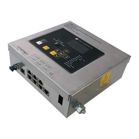
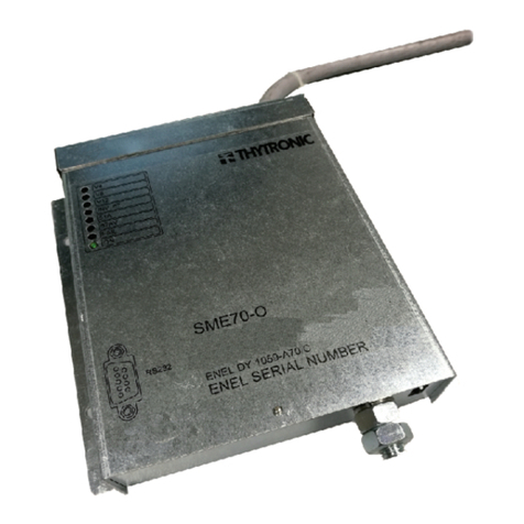
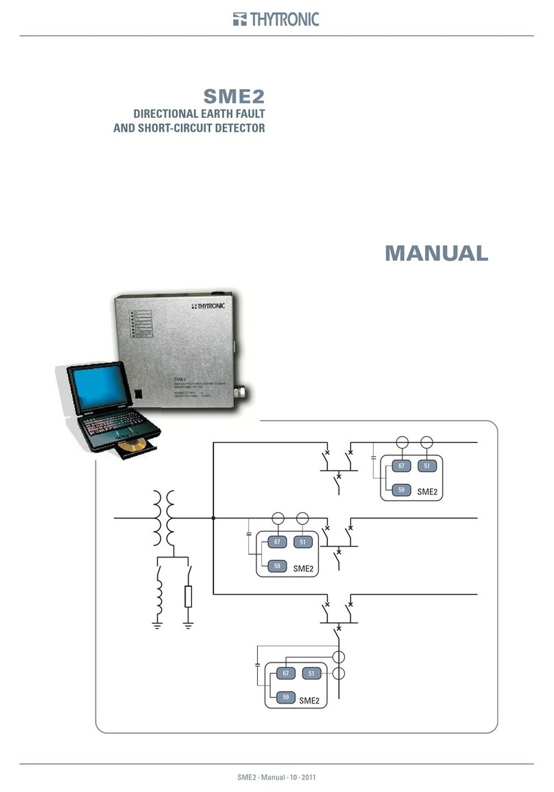
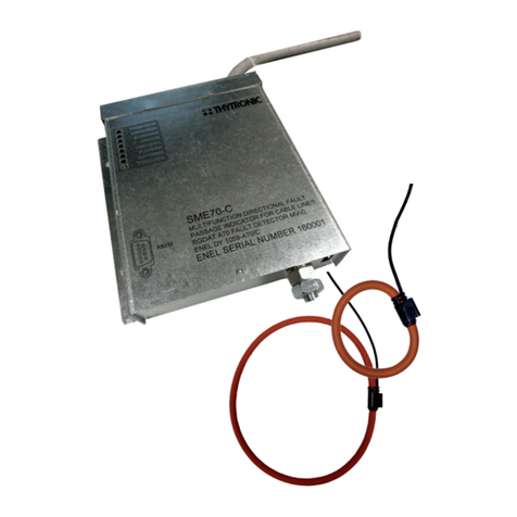
Thytronic SME2-IS User manual

INSTALLATION GUIDE SME2-IS - 06|2021
INSTALLATIONINSTALLATION
Scope and liability
SME2-IS fault detector are designed in conformity with ENEL GSTP011 (Protection and control devi-
ce for MV substation – RGDM control unit); they are installed in remote-controlled Secondary Sta-
tions to detect phase-phase and phase-ground fault both on neutral compensated and both neutral
isolated with no need of modification switching from a configuration to the other regardless of the
feeding directions.
In particular they allow to:
• detect the presence of multi-phase and phase to ground fault,
• detect the loss of voltage on the line,
• measure the voltage and active and reactive power on MV line,
• operate in case of fault or on remote control from the UP, opening or closing of DY800
• Interface with generators present on the MV line to coordinate voltage regulation along line and
remote trip signals.
Input circuits are suitable to acquire measurements using integrated current-voltage phase sensors;
device can acquire, using a software switch, current measurements inputs using active sensors
(signal is proportional to the current detected by sensor) or passive sensors (DJ 5400 e GSTC005
- signal proportional to the value of current derivative against time); the device allows current and
voltage measurements using IEC 61869-10 and IEC 61869-11 Low Power sensors.
Omopolar value are obtained through vectorial calculation of current and phase voltage measure-
ments. Two communication Ethernet ports are available, one of them with IEC61850 protocol.
To assure full compatibility with RTU already existing on secondary installations, SME2-IS is equip-
ped with double interface, able to communicate both with UP (DX1215) and with future communica-
tion devices.
Settings, reading measurements and reading of fault recordings can be made using a PC or using
the Ethernet port together with software Thysetter, freely available; all these operations can be made
even using front panel (MMI).
In this manual there are instructions needed to mount, settings and commissioning.
Thytronic keeps the right to improve the product without further notice.
Compliance
This device comply with EU directives about:
• EMC directive: 2014/30/EC
• LV directive: 2014/35/EC
Technical support
Contacts: THYTRONIC Technical service www.thytronic.it
Copyright
All rights reserved; it is forbidden to copy documents without permission of Thytronic, as well as
copy or modify firmware and relative software.
Warranty
The product is under one year warranty.

2
2INSTALLATION GUIDE SME2-IS - 06|2021
Safety informations
The warnings contained in this document are all important for safety; special attention must be paid
to the following symbols:
The devices must be installed and put into operation by qualified personnel with experience in high
voltage installations.
Thytronic assumes no responsibility for damages caused from improper use that does not comply all
warning and caution in this manual.
In particular the following requirements must be met:
• Remove power before opening it.
• Verify the voltage absence by means suitable instrumentation on relay connections; attention must
be paid to all circuits supplied by external sources (binary input, CT, etc...)
• Care must be taken when handling metal parts. (front panel, connector).
Insulation test
Following dielectric strength tests and / or insulation resistance measurement may occur dangerous
voltages (charging of capacitors, etc ...); it is recommended not to abruptly stop the test voltage, but
rather to reduce it gradually until you reach a zero level.
Connections
SME2-IS must be connected as shown in the technical sheet.
On the device are shown following indication:
- identification of manufacturer and model,
- connection diagram,
- terminal identification,
- identification of nominal value of supply voltage and current.
Therefore, we exclude the possibility of damage due to a wrong supply of the relay.
Environmental conditions
Device must be used in environmental conditions indicated in technical specifications.
For application under different conditions, appropriate actions must be provided before commissio-
ning (conditioning systems, humidity control, etc ...). In case of presence of polluting elements (dust,
corrosive substances, etc...) it is necessary to provide appropriate filters.
Protections against electrical shock
The relay does not have accessible conductive parts that can be live under fault conditions. The in-
sulation distances are adequate to ensure the insulation seal; the dielectric strength tests were per-
formed with respect to the housing (Protection earth), as the test report given in the specifications.
Given the fact that the relay is intended for installation in panels or closed cabinets, considering that
the electrical terminals are not accessible to the operator, therefore the product does not represent
a hazard of electric shock.
In accordance with the product standards, the relay is not equipped with any switch of the power
source device. In case of a short circuit within the relay will not be produced danger to the operator.
Protection again mechanical hazards
Accessible parts of the relay have no projections or sharp or pointed edges. There are no mechani-
cal moving parts.
The mechanical strength test and the impact test are passed without damage, according to the test
report given in the specifications.
The relay is not subjected to the drop test as it is intended for fixed installation.
Protection against overheating
The heating of the different parts of the relay is limited within values such as not to create dangerous
conditions neither for the operator nor for the components and the materials of which the relay is
made.
The behaviour on these fault conditions does not lead to any hazardous condition:
- Overload or short circuit after the auxiliary power supply terminals,
- Overload or short circuit after the relay internal power supply circuit.
The heating of the current input circuits, due to the permanent or thermal overload, does not cause
permanent damage.
Other risk
There are no hazards from fluids, as they are not present.
The relay does not produce, both in normal operation and in case of failure, any type of radiation
nor any acoustic phenomenon. The relay does not produce, both in normal operation and in case of
failure, any appreciable emission of harmful gases.
CAUTION Minor personal injury or property damage can result if proper precautions are not taken

3
INSTALLATION GUIDE SME2-IS - 06|2021
Mounting
For mounting proceed as follows:
• open the cover
• secure the SME2-IS panel using the supplied four M5 screws on the previously machined panel
according to the drilling template indicated in the installation drawings.
• if necessary, interpose the supplied anti-vibration support between the device and the bottom pa-
nel.
Connection to sensor
The current/voltage sensors must be connected to the RJ45 connectors.
The cables are preassembled to the sensors.
Make sure to observe the phase-to-phase direction L1-L2-L3.
Select the type of sensor by setting the respective parameters in the menu Set \ Sensor selection:
SP for passive sensors
CVS for active electronic sensors
Connection to communication
ports
Links to communication ports must reach for the RJ45 socket for local connection and for the LC
socket (optical fiber) for connection to the field bus.
The devices must be installed and put into operation by qualified personnel.
Thytronic assumes no responsibility for damages caused from improper use.
CAUTION
Assembly
100 m m
150m m
Ø 5.5 m m Ø 5.5 m m
Ø 5.5 m m
Ø 5.5 m m
serial-sch.ai
Ethernet 100 BaseT port
for local connection (ThyVisor)
Ethernet 100 BaseT port
to connect to fieldbus
(IEC61850)

4
4INSTALLATION GUIDE SME2-IS - 06|2021
SME2-IS
L1
L2 BARS
L3
Smart Terminal sensor inputs
L1-ST, L2-ST, L3-ST
IL1-UL1
IL2-UL2
IL3-UL3
P1
P2
Low Power sensor inputs
Capacitive
voltage
divider
input L1-LP, L2-LP, L3-LP
IL1-UL1
IL2-UL2
IL3-UL3
P1
P2
LC
NORMAL POWER
SUPPLY DIRECTION
INTERVENTION
MBTERMINAL BLOCK
COMTS (+24VDC)
TS 51A
TS V
M1
+
+TS 67AV
M2
UD
D/A
COM UD
- (-24VDC)
+24Vcc
1
2
3
4
5
6
7
8
9
10
MITERMINAL BLOCK
+M
+M
+A
+L
-A
-M
-M
ccx 89
cax 89
TC CCX
TC CAX
1
2
3
4
5
6
7
8
9
10
K4
K5
K1
K2
K3
11
AnIn
RVS
12
13
Actuator (OdM)
Connection to remote control unit
(basic configuration)
ETHERNET TX
MUTERMINAL BLOCK
to Router
+ 24 VDC
+ 24 VDC
- 24 VDC
- 24 VDC
+L
1
2
3
4
5
ETHERNET FX
Use of alternative sensors
Capacitive voltage divider
for voltage present lamps
MI_A
MI_S
Connections

5
INSTALLATION GUIDE SME2-IS - 06|2021
Terminal Board Connections
For the terminal blocks MB, MI, MU are available screw terminals, reachable inside the device, with
the following characteristics:
• cable section: from 0.2 to 2.5 mm2(AWG 30...12) for single wire
• tightening torque 0.5 Nm
• stripping length: 6 mm
Ground connection
It is requested the ground protection connection, that must be wired to the screw terminal provided
for that purpose.
Settings and commissioning
Settings of protection function can be made:
• Using a Personal Computer, with ThyVisor software installed.
• Locally using keyboard and display (MMI).
The ThyVisor sw is a viewer and configurator of data (setting, measure, etc..); it implements an en-
gine that is able to rebuild the menu set up and the relationships to data, concerning all Thytronic
protecion relays by means of XML files.
ThyVisor installation
The latest release of ThyVisor can be downloaded free of charge from the www.thytronic.it website.
ThyVisor use
Please refer to ThyVisor user manual for detailed instructions.
The document is available on www.thytronic.it.

6
6INSTALLATION GUIDE SME2-IS - 06|2021
MMI (Man Machine Interface)
On the front panel there are eight buttons which allow the user to perform all the settings, reading
and modification operations.
The adjustment of the settings and the operation mode of the output relays must be performed while
the unit is electrically powered;
All preset values are permanently stored in the nonvolatile memory.
The buttons take the following operations:
- (Up) move the cursor upwards to the preceding menu options
- (Down) move the cursor downwards to the subsequent menu options
- (Left) move the cursor upwards to the preceding menu options
- (Right) move the cursor downwards to the subsequent menu options
- (Enter) access to the selected menu with the option of modifying any given parameter
- (Reset) abort the current changes and/or accessing the previous menu
- Circuit breaker Open command
- Circuit breaker Close command
- Enables the Hot Line Tag function
At power on, the IP address of the ethernet port (TX) appears in the first line at the top.
The ON green Led points out the auxiliary power supply voltage (permanent lighted) and possible
faults (blink lighted).
The display backlight is automatically activated when any key switch is set.
By means of the Up or Down buttons, it is possible to cyclically browse through the menu options: CLOCK
ADJUST, READ, SET, COMMUNICATION, TEST.
Having identified the sub-menu of interest, it is possible to gain access by using the Right and then
analogously, run through the relevant options by using the Up or Down.
The full menu tree and some examples are showed in the following pages (numerical values and
settings are pointed out as examples and does not agree with real situations.
Reading variables (READ)
All data (measure, settings, parameters, etc...) can be displayed; they are arranged in functional
group submenus.
Setting modifying (SET)
For security reasons it is sometimes requested that any change of the settings using MMI is di-
sabled. In this way only qualified personell will be able to modify settings using software ThyVisor.
Changes can be made with MMI only if the parameter “Enable Settings by MMI” is active. (SET\
MMI\PARAM SETTINGENABLE) This parameter is changeable only using program.
To effect a change, having identified the parameter intended for change, the following procedure
must be performed:
• Select the parameter going through the menus by means the Up, Down and Right keys
• Press theEnter button for a few seconds; the modification in progress status is highlighted by fla-
shing of the 51-51N, 67NLEDs and by appearance of the pointer on the bottom.
• Move the cursor over the parameter intended for change using the Enter.
• Change the parameters by means the Up(increment) or Down (decrement).
o

7
INSTALLATION GUIDE SME2-IS - 06|2021
• Press the Enter button to move the cursor over the last parameter in the display.
• Press again the Enter button; pointer disappear and LED 67N, while LED 51-51N continue to blink.
• Press the Enter button for a few seconds; new message appears:: “Conrm settings?”
• Answer to the message ENTER: YES to confirm changes or RESET: NO to abort.
The end of LEDS blinking spoints out the end of procedure; the changes become right now
active.
The RESET command may be used to abandon changes (prior to use ENTER: YES); the same
effect is achieved by removing the auxiliary power supply to the relay.
As example, to set the operating mode of the K1 output relay as ENERGIZED, LATCHED, the following
procedure must be issued:
• Select the menu Set “SET >>”by means of the buttton Down.
• Press the button Right to enter menu; the following submenu title i displayed: “BASE >>”
• Scroll menus by means Down button
• Select the SET menu“RELAYS >>”, the “K1 relay Setpoints >>” message is displayed.
• Press the button Right to enter; the following messages are displayed:
“Logic DE-ENERGIZED
Mode NO LATCHED
Min. pulse width
tTR1 150 ms”
• Press the button Enter for few seconds; lthe modifi cation in progress status is highlighted by
the both LED51-51N e 67N.
• Move the cursor over the parameter intended for change using the Enter button, (in our case on
the message “Logic DE-ENERGIZED”),
• Change the parameters by means the Up or Down “Logic ENERGIZED”,
• Press the button Enter for a moment to move the cursor over the last parameter in the display,
“Mode NO LATCHED”,
• Change the parameters by means the Up or Down, “Mode LATCHED”,
• Press the Enter button for a moment to select the last parameter showed on the display, “150 ms”,
• Press again the button Enter; the pointer disappear and the LED 67N turn off, while LED 51-51N
keeps blinking.
• Press the button Enter for few seconds; new message appears: “Conrm settings?”
• Answer to the message ENTER: YES to confirm or RESET: NO to abort
The end of the two LEDs blinking points out the end of procedure.
Circuit breaker commands
By means of the (Open) or (Close) the circuit breaker commands may be issued.
These commands are enabled only in local operation (LED Local on).
Example:
• Press the button to open: appear the message: “OPEN CB? ENTER:YES RESET NO”
• Answer to the question ENTER: YES to confirm opening or RESET: NO to abort.

Sede: 20139 Milano - Piazza Mistral, 7 - Tel. +39 02 574 957 01 ra - Fax +39 02 574 037 63
Stabilimento: 35127 Padova - Z.I. Sud - Via dell’Artigianato, 26 - Tel. +39 049 894 770 1 ra - Fax +39 049 870 139 0
www.thytronic.it www.thytronic.com thytronic@thytronic.it
Other manuals for SME2-IS
1
Table of contents
Other Thytronic Security Sensor manuals
Popular Security Sensor manuals by other brands

Acorn
Acorn Zeta Simplicity CO installation manual
INIM
INIM Aurora S3500 installation instructions
schmersal
schmersal ZQ 700 operating instructions

System Sensor
System Sensor B110RLP Installation and maintenance instructions
FM Electronics
FM Electronics 4190-GB quick start guide

Texecom
Texecom Premier Elite Impaq Plus-W instruction manual
