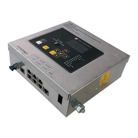
Thytronic SME2 User manual

SME2 - Manual - 10 - 2011
SME2
DIRECTIONAL EARTH FAULT
AND SHORT-CIRCUIT DETECTOR
MANUAL
51 67
59 SME2
SME2
SME2
51
67
51 67
59
51
67
51 67
59
51
67

2SME2 - Manual - 10 - 2011
1 G E N E R A L
1 GENERAL
General info
SME2 fault detection systems are designed in conformity with the ENEL DY 1059 (RGDAT) specifica-
tion; they are installed in remote-controlled Secondary Stations in order to provide local and remote
signalling of short circuit and earth faults that may occur in MV distribution networks. SME quickly
locate the line section affected by the fault thus reducing power outage.
The SME2 device uses the signal provided by the capacitive voltage dividers fitted on MV panels
both for the directional earth function and for the voltage failure detection function; the phase volt-
age values V4, V8 and V12 are processed so as to eliminate the capacitive divider measurement
errors by means of a self calibration algorithm.
The current measure is taken by three open core current transformers supplied in the kit.
The SME2 device detects faults between phases producing a current exceeding the threshold and
earth failures both on insulated neutral networks and on compensated neutral networks, without
any need of changing the settings between different configurations and regardless of the feeding
direction.
The device detects faults lasting more than 80 ms and is not sensitive to self-restoring faults lasting
up to 40 ms.
The correct detection of the fault direction also occurs in the presence of intermittent faults.
The SME2 device checks the voltage of the three phases of the MT line and indicates whether it is
ON or OFF; a current converter is also available with an impressed current output of 4...20 mA for
sending the phase current measurement to the remote control terminal.
The device is provided with a self-calibration function capable of correcting errors and drifts (ageing
or thermal) of capacitive transducers used to detect phase voltages.
The following output relays are provided:
TS51A relay; it signals the short circuit function tripping for phase faults (between phases or dou-
ble-phase to earth),
TS67AV relay; it signals the directional earth function tripping in case of line faults (with reverse
direction disabled),
TSPRESV relay; it signals the dead line function tripping.
The following LEDs are provided:
three green-coloured LEDs indicating the voltage presence on V4, V8, V12 phases,
a white-coloured LED indicating the activation of the reverse direction for the directional earth
protection,
an orange-coloured latched LED indicating trip of the multiphase or double-phase to earth protec-
tion,
a red-coloured latched LED indicating the trip of the earth fault protection ,
a red-coloured LED indicating the calibration in progress,
a red-coloured LED indicating the self test function (blinking).
A logical input allows enabling the reversal command for earth fault directional protection (67).
Protective functions
51 Phase overcurrent
67 Directional ground fault overcurrent
59 Voltage presence
•
•
•
•
•
•
•
•
•
•
•
•

3
SME2 - Manual - 10 - 2011
2
2
MAIN FEATURES
MAIN FEATURES
SME panel
The SME2 panel is suitable for projecting assembly.
The front includes signalling LEDs and communication port.
Phase Current Sensor
Two open core ring type current transformers are designed so as to be mounted directly on the
medium voltage insulated cables.
Residual current sensor
The IE> sensor is an open core ring type current transformer.
The sensor is installed on insulated cables so as the earth connection of the cable armour must pass
through the transformer.
Since the core embeds the three line phases, the residual current is detected.
Current sensors connections
Current sensors connections are implemented through a harness conforming with the ENEL DY1059
specification; they must be connected to the MA terminal board located inside the SME2 panel.
Voltage sensors connection
(Capacitive dividers)
Voltage sensors connection is implemented through screened cable between the fixed outlet on the
MV panel and the SME2 device through hexapolar plug conforming with the ENEL DY811 specifica-
tion.
Remote control unit
Remote control unit connections are implemented according with ENEL DY1059 specification; they
are abutted to the terminal board MB at the factory according to the connection diagram into the
device cover.
RS232 communication
The device provides a serial interface to allow a PC connection for installation, configuration, moni-
toring and diagnostic.
The firmware upgrade is provided.
To connect to the PC an adapter may be provided on request (SOC003 converter).
3
3
FUNCTION CHARACTERISTICS
FUNCTION CHARACTERISTICS
The SME2 device performs its fault detection functions based on measure of line currents and phase
voltages; two phase currents, three phase voltages and the residual current are detected.
The following features are provided.
Earth single-phase fault
directional detection function
The function detects the occurrence of earth faults both on insulated neutral networks and on com-
pensated neutral networks, without any need of changing settings when changing type of network.
The algorithm is based on the numerical analysis of signals (FFT) through fast sampling (64 samples
per period) and phase locking algorithm (PLL); in this way the quantities are correctly measured in
Through external signal from the remote control system, it is possible to control the reversal of the
reference direction in case of line feeding from the opposed side (secondary station bar tripping
directionality); the reversal signal is provided by the remote control system through the closing of a
contact connected to terminals 8 and 9 of the MB terminal board.
The fault signal (TS67AV) is provided to the remote control unit by the closing of a contact connected
to terminal 5 of the MB terminal board.
The sensitivity of the earth directional function depends on the extension of the line and on the neu-
tral status (insulated or with Petersen coil).
The setting is based on the adjusting of a U0residual voltage[1] threshold adjustable in the 1...16% Un
range and a I0zero sequence current [2] adjustable in the 1...9 A range.
The protective element detects the directional earth fault if all the following conditions occur:
Residual voltage exceeds the U0> threshold ,
Residual current exceeds the IED> threshold IED>,
Residual current - residual voltage displacement between 60 ° and 255 ° (IED lags behind to U0with
reversed direction disabled),
All the above conditions were met for almost 80 ms.
Note 1 - The residual voltage U0is the vector sum of the three phase voltages divided by three.
Note 2 - The residual current IE is the vector sum of the three phase currents.
Double earth single-phase
or phase-phase (short circuit)
fault detection function
The L4 and L12 phase currents are measured and fault indication is provided when current in at
least one phase exceeds the set threshold a:
500 A for multi-phase faults
150 A for double earth-phase faults).
The fault signal (TS51A) is provided to the remote control unit by the closing of a contact connected
to terminal 2 of the MB terminal board.
•
•
•
•
•
•
•
•
•

4SME2 - Manual - 10 - 2011
Voltage presence
The three phases voltages are measured; when at least one voltage value is higher than 80% of the
rated voltage the information (TSV) is provided to the remote control unit by the closing of a contact
connected to terminal 3 of the MB terminal board.
Current converter
The SME2 device is provided with an impressed current analogue output for sending the phase cur-
rent measure to the remote control unit. Signal 4...20 mA is available for transfer to the remote control
unit on terminals 4 (M1 connected to the positive auxiliary power) and 7 (M2 of terminal board MB).
The rated primary current is adjustable inside the 100...500 A range with 100 A step.
Calibration
The calibration procedure aims to adjust the SME2 device voltage inputs to the capacitive dividers
mounted on secondary switchgears; it should be carried out without faults on the network.
The self calibration The phase voltages and acquired and the voltage parameters are normalized.
The automatic calibration process is started with PC command.
The computed parameters are stored to a nonvolatile memory and maintained when auxiliary power
is goes down.
Output relay commissioning
The output relays TS51A and TS 67AV trip as for faults causing the switch to open, as for transient
faults. Relays are energised for the fault time, and in any case for a minimum of 150 ms.
The following cases are covered:
single-phase ground fault with residual current IE≤ 150 A: the directional protection trips (67) if the
direction is correct,
single-phase ground fault with current IE> 150 A: the short circuit (51) protection trips,
double single-phase earth fault with current IE≤ 150 A (on the same line or on different lines): the
67 trips if the direction is correct,
double single-phase earth fault with current exceeding 150 A (on the same line or on different
lines): the 51 protection trips,
multi-phase fault with residual current IE> 500 A: the 51 protection trips.
voltage presence indication: the TSV relay remains energised as long as the three phase voltages
remain below the voltage off threshold (20% Un).
The operation of directional earth fault protection (67) is masked by the trip of the phase overcurrent
protection (51) according to the logic shown in Figure below.
Voltage presence
Two thresholds are provided:
80% of rated voltage for trip (4% accuracy),
20% of rated voltage for reset (4% accuracy).
The transition between the states of presence / absence voltage is described:
Starting from the no voltage condition (Voltage Presence OFF), the logic state of supply voltage is
detected when, for at least 250 ms the following condition is true:
(V4>80%Vn) OR (V8>80%Vn) OR (V12>80%Vn)
Starting from the condition of Voltage Presence ON, the logic state is no longer recognized if the
following condition is true:
(V4<20%Vn) AND (V8<20%Vn) AND (V12<20%Vn) without intentional delay.
In case of fall and recovery of 24 VDC power supply, the logic state starts no voltage condition (Volt-
age Presence OFF) and only if the following condition is true:
(V4>80%Vn) OR (V8>80%Vn) OR (V12>80%Vn) the voltage presence is recognized
•
•
•
•
•
•
•
•
•
•
•
0.15 s
t
67 trip
51 trip
Operating logic for masking the 67 trip implemented through
the trip of the 51 protection

5
SME2 - Manual - 10 - 2011
The voltage presence logic is shown
Led indicators management
The SME2 device is provided with 8 indicator LEDs:
three green LEDs indicating that V4, V8, V12 phase voltages are ON,
a white LED indicating the direction reversal for the directional earth protection,
an orange LED indicating the multiphase or double single-phase function tripping,
a red LED indicating the earth fault function tripping downstream of the device,
a green LED indicating the calibration in progress condition,
a red LED indicating the self-test function tripping.
The fault indicator LEDs light up when a fault occurs which causes the opening of the switch, and
they remain open until the three phase voltages return and remain for at least one second at a value
of more than 80% the rated phase voltage.
The V4, V8, V12 LEDs, light up if the voltage of the relative phase is greater than 0.8 Vn and go OFF
when the voltage is less than 0.2 Vn.
Glossary/definitions
50/51 Phase overcurrent ANSI code
59 Voltage presence ANSI code
67 Directional ground fault ANSI code
Vn Rated voltage
In Rated current (500A)
V4, V8, V12 Phase voltages
I> Phase overcurrent threshold (51)
t> Operate time (51)
IED> Directional ground fault threshold (67)
U0> Residual voltage threshold (67)
tED> Operate time (67)
U> Voltage presence threshold (59)
•
•
•
•
•
•
0.2 Un
0.8 Un
Voltage presence (59)
Voltage presence status (59)
Voltage presence LED (59)
V4, V8, V12
t
V4, V8,V12
0.25s

6SME2 - Manual - 10 - 2011
4 T E C H N I C A L D A T A
4 TECHNICAL DATA
4.1 GENERAL
Insulation
Reference standards EN 60255-5 IEC 60255-5
High voltage test (50 Hz 60 s)
Auxiliary power supply 1 kV
Input circuits 1 kV
Output circuits 1 kV
Output circuits (between open contacts) 1 kV
Impulse voltage withstand test (1.2/50 μs):
Auxiliary power supply 2 kV
Input circuits 2 kV
Output circuits 2 kV
Output circuits (between open contacts) 2kV
Insulation resistance >100 MΩ
EMC tests for interference immunity
Reference standards
Product standard for measuring relays EN 50263
Generic standards immunity for industrial environments EN 61000-6-2
Apparati di automazione e controllo per centrali e stazioni elettriche (ENEL utility standard)
- Compatibilità elettromagnetica - Immunità ENEL REMC 02
- funzione del rivelatore di guasto protezione
- ambiente di installazione stazione MT
- porta di segnale collegamenti locali
Climatic tests
Reference standards IEC 60068-x ENEL R CLI 01 CEI 50
Ambient temperature -10...+55 °C
Storage temperature -40...+85 °C
Relative humidity 10...95 %
Atmospheric pressure 70...110 kPa
Mechanical tests
Reference standards
- Normativa di compatibilità elettromeccanica
per apparati e sistemi (ENEL utility standard) ENEL REMC 01
Reference standards
Rivelatore di guasto direzionale (RGDAT) (ENEL utility standard) ENEL DY 859
Prescrizioni per la costruzione ed il collaudo ENEL DY 1059 Ed.02-2004
Other applicable standards
Electric relays EN61810-1 (ex CEI 41-1) IEC 60255
Protection degree (IP code) EN60529, EN60529/A1
EMC Directive 89/336/EEC
Low Voltage Directive 73/23/EEC
Technical data
Mounting:
Phase current transformer on isolated cable
Residual current transformer on isolated cable
SME2 device Projecting
Protection degree IP31
SME2 mounting position vertical
Mass:
Phase current transformer 0.3 kg
Residual current transformer 0.7 kg
SME2 device 0.9 kg
•
•
•
•
•
•
•
•
•
•
•
•
•
•
•
•
•
•
•
•
•

7
SME2 - Manual - 10 - 2011
4.3 Input circuits
Auxiliary power supply Uaux
Rated voltage 24 V-
Nominal value (range) 19...29 V-
Max alternating component 10%
Maximum time at power ON 0.10 s
Power consumption at rest condition 2.5 W
Max power consumption 4 W
Phase current transformer
Inside diameter 50 mm
Rated current In500 A
Permanent overload 4 In
Thermal overload (1 s) 100 In
Dynamic overload (10 ms) 250 In
Frequency:
Rated frequency fn50 Hz
Operative range 0.95...1.05 fn
Connection to SME2
type unipolar wires
section 1 mm2
length 3.5 m
Residual current transformer
Inside diameter 150 mm
Permanent overload 1 kA
Thermal overload (1 s) 12.5 kA
Dynamic overload (10 ms) 31.5 kA
Frequency:
Rated frequency fn50 Hz
Operative range 0.95...1.05 fn
Connection to SME2
type unipolar wires
section 1 mm2
length 3.5 m
Phase voltage input circuits
Voltage plug DY811
MV rated voltage 15, 20, 23 kV
Transformation ratio 200...1800
Capacitive reactance (MTV side) 100...700 MΩ
Connection to SME2
type shielded wires
section 0.5 mm2
length 3.5 m
Binary input
Quantity 1
Type optocoupler
Operative range rated Uaux
Max consumption, energized 3 mA
4.4 Output circuits
Relays
Quantity 3
Type of contacts make (SPST-NO, type A)
Nominal current 2 A
Nominal voltage 250 V
Breaking capacity (24 V, L/R = 40 ms) 0.2 A
Minimum switching load 300 mW (5 V/5 mA)
Current converter
Operating range 0...500 A
Output current 4...20 mA
Accuracy 10%
Max load 750 Ω
Maximum response time 300 ms
•
•
•
•
•
•
•
•
•
•
•
•
•

8SME2 - Manual - 10 - 2011
4.5 LEDs
Signalling LEDs
Voltage presence (V4) green LED
Voltage presence (V8) green LED
Voltage presence (V12) green LED
Trip direction IED> (INV 67) white LED
Trip I> (51A) orange LED
Tripe IED> (67AV) red LED
Calibration in progress (CALIBRATION) red LED
Self test red LED
Connection to the remote control unit
Type 9 wires multipolar cable
Section 1 mm2
Length 8 m
4.6 COMMUNICATION INTERFACE
Local port
Connection RJ45
RS232-copper adapter SOC003
Rate 9600 Bps
Parity None
Protocol ModBus RTU®
4.7 PROTECTION AND CONTROL FUNCTIONS
Overcurrent (51)
I> threshold (1) 500 A
Operate time (definite time characteristic) 0.12 s
Dropout ratio > 0.95
Reset delay 0.02 s
Duration of the fault not detected 0.04 s
Duration of the fault detected 0.08 s
Reference values rest: 0
trip: 1.2 I>
Threshold accuracy ±10%
Operate time accuracy ±3% ± 20 ms
Note 1: For multi-phase faults the operating threshold is 500 A, for single-phase or multi-phase double earth fault the operating threshold is 150 A
Voltage presence (59)
U> threshold 0.80 Vn (1)
Operate time (definite time characteristic) 0.25 s
Dropout ratio 0.25
Reset delay 0.04 s
Reference values rest: 0
trip: 1.0 Vn
Threshold accuracy ±4%
Operate time accuracy ±3% ± 20 ms
Note: The 59 protection trips when the value of at least one phase voltage is greater than 0.8 Vnand is reset when the voltage of all three phases is
less than 0.2 Vn.
•
500 A I
t>
I>
t
TRIP
General operation time characteristic for the phase overcurrent element - 50/51
500 A I
t>
I>
t
TRIP
General operation time characteristic for the phase overcurrent element - 50/51

9
SME2 - Manual - 10 - 2011
Directional earth fault overcurrent (67)
IED> threshold (1) 1.0...9.0 A (step 0.5 A)
U0> threshold 0.01...0.16 Vn(step 0.01 Vn)
Operate tED>(definite time characteristic) 0.15 s
Dropout ratio > 0.95
Reset delay 0.03 s
Duration of the fault not detected 0.04 s
Duration of the fault detected 0.08 s
Reference values rest: 0 V, 0 A
trip: 2IED>,2U0>
Threshold accuracy ±15%
Operate time accuracy ±3% ± 20 ms
Angular sector accuracy (U0=1...120%; IE=1...150 A) ±2°
Hysteresis on the sector output ≤ 3°
Note (1) The directional earth fault function operate whenever the set residual voltage threshold U0> is exceeded with a residual current IE>
higher than threshold with a defined phase relation.
The masking time as voltage is restored is 0.15 s.
The operation of the directional earth fault protection is masked by the overcurrent trip according to
the logic function described below:
t
Uo
Uo>
IE>
Uo
IE
IE
tED>
TRIP
General operation time characteristic for the 67 element
TRIP
t
Uo
Uo>
IE>
Uo
IE
IE
tED>
TRIP
General operation time characteristic for the 67 element
TRIP
U
0
I
E
IE>
IE>
60˚
90˚ 90˚
NO TRIP
NO TRIP
TRIP
TRIP
157.5˚
180˚
255˚ 240˚
270˚
U
0
I
E
75˚
157.5˚
180˚
270˚
Polar tripping characteristic (67) with reversing direction OFF Polar tripping characteristic (67) with reversing direction ON
Operating logic for masking trip of the 67 protection with trip of the 51 protection
0.15 s
t
67 trip
51 trip

10 SME2 - Manual - 10 - 2011
5 I N S T A L L A T I O N
5 INSTALLATION
SME2 device For fixing you must:
remove the cover by unscrewing the fastening screws;
fix the SME panel fitting the four M5 screws supplied into the holes on the case bottom; the opera-
tion is made easier by the presence of the slotted holes.
Current sensors
Since current shorting connectors are not provided for the secondary CT’s, the current sensors must
be installed at the same time with the SME device and connected at once. In case of replacing
and/or maintenance operation of amperometric circuits, it is indispensable that the circuit breaker
is OFF.
Since the earth fault detection function is directional, the toroid fitting direction must be complied
with, or the device could fail to operate.
The assembly of the current sensors must be performed in the same way for feeders or incoming
lines (operation according to the output direction from the switchgear).
Phase current sensors
For fixing you must:
split the two core parts removing the metal clamp fastening screw;
fit the core to the phase conductor by properly coupling the two parts forming the sensor and
make attention that the earth connection of the cable shield don’t pass through the sensor. The
two phase current sensors supplied into each package have a different colour with respect to the
container for an easier coupling; in particular, the two half-cores should be aligned properly so
that references “P1” on the same cores are matching. For mechanical stability reasons, the sensor
fitting direction should be such as to have said references arranged towards the upper side of the
MT switchgear.
apply the metal clamp and tighten the fastening screw;
anchor the core to the phase conductor using the insulating clamps supplied.
Residual current sensor
Note: for use on MV grid the installation on insulated cables is required!
Before fitting, make sure that there are no earth connections of the screens upstream of the sensor;
in particular, for unified unipolar terminal ends, insulate support brackets from earth using the com-
ponents supplied in the kit to the MT switchgear. Fig. 5, illustrating the assembly drawing of the entire
compartment, shows the layout with plates, screws and insulating bolts. For different applications,
refer to the MV panel manufacturer’s instructions.
For a perfect sensor fitting, the three earth connection screens should be collected into a single
bundle to be anchored to the central cable so as to implement an ordered fitting (fig.5); proceed as
follows:
split the two core parts removing the metal clamp fastening screw;
fit the toroid so as to embrace the three cables, making sure that also the screening braiding earth
connection is included;
apply the metal clamp and tighten the fastening screw; align the two half cores properly so that
references “P1” on the same cores are matching.
The sensor fitting direction should be such as to have said references arranged towards the upper
side of the MV compartment (line outgoing side downstream of switch).
fasten the core using the insulating clamps supplied.
•
•
•
•
•
•
•
•
•
•
•
Mounting on unshielded cables Mounting on shielded cables
Isolated cables

11
SME2 - Manual - 10 - 2011
In order to ensure a linear response from the sensor, the cables must be positioned in the centre
of the transformer so that the magnetic effect of the three cables is perfectly compensated in the
absence of residual current (Correct installation).
Hence, the assembly indicated in the drawing (Improper installation), in which phase L3 causes local
magnetic saturation whereby the vectorial sum of the three currents would be non-null, should be
avoided.
The same considerations also apply when the sensor is positioned near bends in the cabling.
It is recommended that the transformer be placed away from bends in the conductors).
Electrical connections
Electrical connections must comply with the connection diagram shown on the inside of the SME2
panel cover; they include:
1) connection to the current sensors;
2) connection to the remote control unit;
3) connection to the capacitive dividers;
4) connections to the earth terminal.
1) Fit the connection cables to the Ct’s through the fair lead provided in the lower side of the case for
a minimum length of 20 cm. Connect the cables to MA terminal board; the operations are made easier
by the marks on the conductors and by the signatures print on the PCB.
2) As regards the connection to the remote control unit, the cable is supplied already abutted to the
MB terminal board.
3) The connection cable to voltage sensors (capacitive dividers) is supplied already abutted to the
MA terminal board, so you only have to connect the hexapolar plug to the relevant outlet (voltage
on lights).
4) Connect the case to earth and implement the earth node between current sensor return conduc-
tors (CT).
Final operations
After wiring, make sure that no bare parts off the components come in contact with the circuit. As
further precaution it is advisable to mechanically secure connection cables to the sensors, to ca-
pacitive dividers and to the remote control unit outside the SME2 panel, so as to prevent the cables
from exerting any stress on the terminals.
L1
L2 L3
L1
L2 L3
>3 D
Diameter D
CORRECT INSTALLATION IMPROPER INSTALLATION
L1
L2 L3
L1
L2 L3
>3 D
Diameter D
CORRECT INSTALLATION IMPROPER INSTALLATION

12 SME2 - Manual - 10 - 2011
6 COMMISSIONING
6 COMMISSIONING
For start up, apply the auxiliary power voltage fitting the connector in the remote control outlet.
Upon start up, all of the eight leds are controlled to light up for 1 s; afterwards, they turn off except
for led V4, V8, V12, if voltage on the corresponding phases is ON.
In order to check the device operation, it is possible to measure the current input of the auxiliary
power which, at rest conditions with voltage equal to the rated value of 24 V, must be within the
90 ... 130 mA range.
The settings must be made by Personal Computer with sw ThySetter
6.1 ThySetter
The ThySetter sw is a “browser” of data (setting, measure, etc..); it implements an engine that is
afford to rebuild the menu set up and the relationships to data concerning all Thytronic protective
relays by means of XML files.
Following operations are performed by means ThySetter:
Open-store of setting files;
ASCII or Excel export reports;
Open/close communication;
Send settings, read settings;
Firmware upgrades;
Session level selection and log enabling (log files);
After the device selection Thysetter allows to:
Set the relay reference data;
Read info, measures, etc... ;
Store settings.
ThySetter installation
The ThySetter sw is available free of charge; the latest version can be downloaded from site www.
thytronic.it (section PRODUCT/SOFTWARE APPLICATIONS/THY-SETTER/download area)
•
•
•
•
•
•
•
•

13
SME2 - Manual - 10 - 2011
6.2 CONNECTION DIAGRAM
6.3 SME2 DEVICE
MB terminal block
to remote control unit
I> current sensor
I> current sensor
IE> current sensor
TRIP
capacitive
divider
normal direction
of power
MA terminal block
SME2

14 SME2 - Manual - 10 - 2011
6.4 CURRENT SENSORS
188
86
83
Ø 150
Ø51
150
Ø5.5 Ø5.5
Ø5.5 Ø5.5
100
6.5 CUTOUT

Headquarters: 20139 Milano - Piazza Mistral, 7 - Tel. +39 02 574 957 01 ra - Fax +39 02 574 037 63
Factory: 35127 Padova - Z.I. Sud - Via dell’Artigianato, 48 - Tel. +39 049 894 770 1 ra - Fax +39 049 870 139 0
www.thytronic.it www.thytronic.com thytronic@thytronic.it
7 MAINTENANCE
7 MAINTENANCE
The SME2 relays do not require any particular maintenance; all circuits use high quality static com-
ponents, the subassembly products undergo dynamic checks on their functioning before the final
assembling of the complete equipment. The dedicated circuits and the firmware for the self-test
function continuously check the relay operation; the continuously operating auto-zeroing function
dynamically corrects the measuring errors due to offset, heat dependent drifts, aging of compo-
nents, etc.
The microprocessor is equipped with a watch-dog circuit which restores the correct operation of
the firmware in case of fault.
8 S T O R A G E
8 STORAGE
The SME2 devices must be stored within the required temperature limits; the relative humidity should
not cause condensation or formation of frost.
It is recommended that the devices are stored in their packaging; in the case of long storage, espe-
cially in extreme climatic conditions, it is recommended that the device is supplied with power for
some hours before the commissioning, in order to bring the circuits to the rating conditions and to
stabilize the operation of the components.
Table of contents
Other Thytronic Security Sensor manuals
