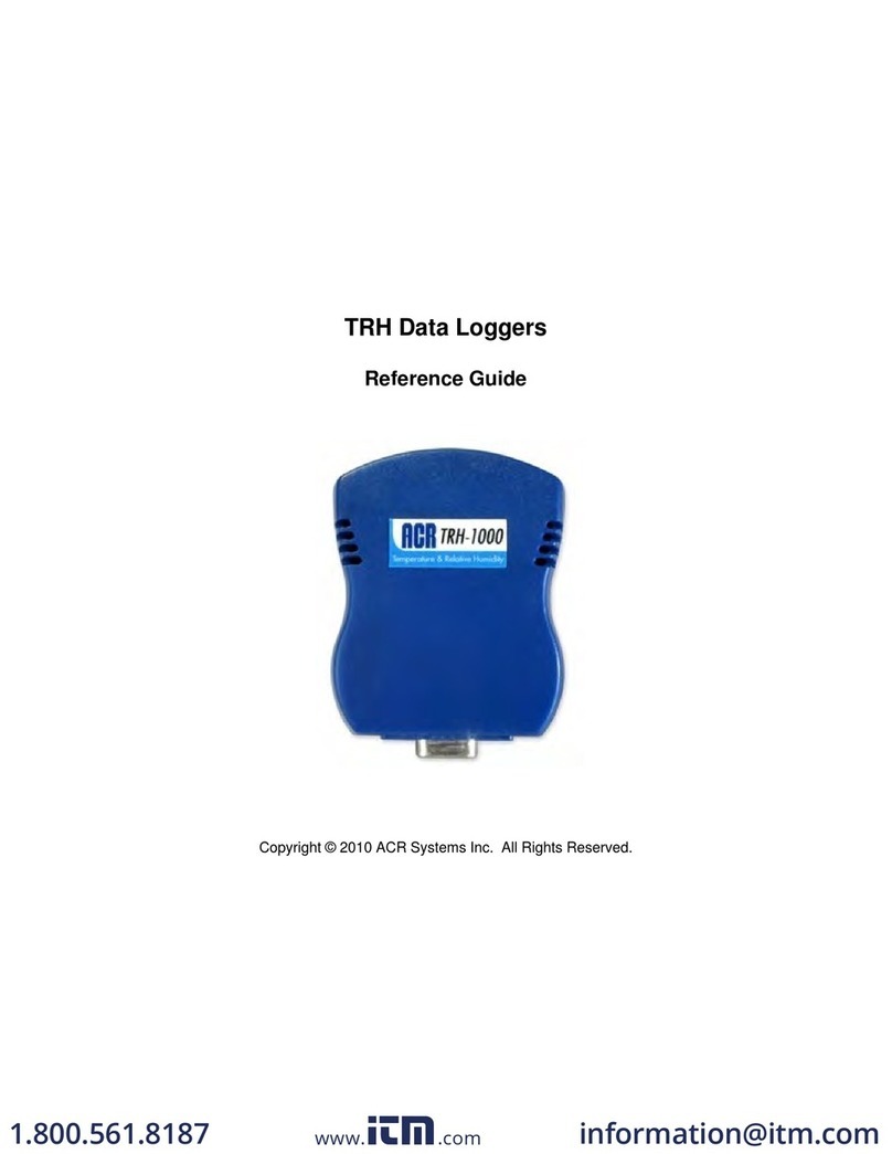
Tidal Engineering Synergy Series User manual

Synergy Controller Technical Manual, Revision H
Nano, Micro 2, and Quattro
For One to Four Channel Systems
Tidal Engineering Corporation
2 Emery Ave
Randolph, NJ 07869
www.tidaleng.com
Document Number TE1813, Revision H: October 18, 2016

Synergy Controller Technical Manual, Revision H
Page 2
Revision History
Rev.
Date
Revision
C
June 16,2005
First Release
D5
June 27, 2006
Added revision page
Updated chapter numbering for sections 8.1.1, 9.7, 11.4
E
October 17, 2006
Updated for Synergy Controller application version 2.0.8.
Added for Synergy Micro 2 Controller configuration.
Updated Overlay and Web Touch Graphics.
Revised Software Upgrade instructions in section 7.
Added LCD Backlight CCFT Lamp Replacement instructions in section 7.
Updated command set Appendix C to 2.0.8 and added examples.
Add section on Macro capability and Bar Code Scanner application.
Added replacement parts list, Section 20 Appendix C.
General document review and edit.
Corrected error in “Analog Retransmit Connections Table”
Revised Output Mapping tables in section 6.10
Revised Synergy Controller Compact Interface Panel Layout figures
F
January 10, 2008
Updated for Synergy Controller application version 2.6.10.
Added UUT Module Mechanical Drawing
Added new section for User Programmable Alarm System.
Added 4-20 mA sensor wiring section.
Added Space and Altitude section
Added Altitude section in L Values for Altitude and Space Chamber Configuration.
Added LabVIEW driver section.
Added Deviation Alarm feature.
Added PID tuning guidelines
Added touch screen calibration for Micro unit
Simplified Olympic board schematic
Added Block Diagram
Added High and Low Res Event Screens
Added Input Calibration section
Added Retro Temperature Only Configuration
Add Safety section
Added USB Bar Code reader setup for Micro applications
Added Installation Section
Added bookmark hyperlinks to document
G
October 5, 2015
Updated for Synergy Controller application software version 3.0.7 Build 893.
Upgraded figures to show Synergy Micro 2 configuration.
Reorganized into 22 sections including 6 Appendices.
Added new section for e-mail features.
Added new section for network printing features.
Updated Space and Altitude section
Added Alarm feature enhancements.
Added touch screen calibration for Micro 2 unit
Simplified Olympic board schematic
Replaced CCFT Lamp replacement with LED upgrade procedure.
H
October 18, 2016
Unified Technical Manual Covers Synergy Controller Software and programming for all
three models: Synergy Micro 2, Synergy Quattro, Synergy Nano

Synergy Controller Technical Manual, Revision H
Page 3
Table of Contents
1.0 INTRODUCTION........................................................................................................................................7
1.1 What’s New.................................................................................................................................................8
1.2 Controller Configurations............................................................................................................................9
1.3 Company Information and Assistance......................................................................................................13
2.0 SPECIFICATIONS....................................................................................................................................14
2.1 Data Sheet................................................................................................................................................14
2.2 Block Diagrams.........................................................................................................................................15
2.1.1 Process Inputs.......................................................................................................................................17
2.1.2 Input Calibration and Scaling.................................................................................................................17
2.1.3 Channel Calibration...............................................................................................................................17
2.1.4 Channel PIDs.........................................................................................................................................17
2.1.5 Channel Primitives.................................................................................................................................17
2.1.6 Channel Setpoints .................................................................................................................................18
2.1.7 User Programmable Alarm System.......................................................................................................18
2.1.8 Logging System.....................................................................................................................................18
2.1.9 Analog Retransmit Outputs ...................................................................................................................18
3.0 APPLICATIONS........................................................................................................................................19
3.1 Environmental Test Chambers.................................................................................................................19
3.2 Process Ovens .........................................................................................................................................19
3.3 Thermal Platforms ....................................................................................................................................19
3.4 Chillers......................................................................................................................................................19
3.5 Other Equipment.......................................................................................................................................19
4.0 EQUIPMENT SAFETY AND CONTROLLER ALARMS...........................................................................20
4.1 Standard Alarm Limits ..............................................................................................................................20
4.2 User Programmable Alarm Limits.............................................................................................................20
4.3 Secondary Controller Alarms....................................................................................................................20
4.4 Alarm System Testing...............................................................................................................................20
4.5 Alarm Notifications....................................................................................................................................21
5.0 FRONT PANEL AND CONTROLS...........................................................................................................22
5.1 Front Panel Layout ...................................................................................................................................22
5.2 User Interface...........................................................................................................................................23
5.2.1 LCD Screen Touch Screen....................................................................................................................24
5.2.2 Function Keys........................................................................................................................................25
5.2.3 Keypads.................................................................................................................................................26
5.2.4 Screen Navigation Keys........................................................................................................................27
5.2.5 Navigating to a Screen Folder Path.......................................................................................................27
5.3 Screen Overview ........................................................................................................................................28
5.3.1 Setup Screen...........................................................................................................................................28
5.3.2 Maintenance Screen................................................................................................................................29
5.3.3 Comm Screen..........................................................................................................................................30
5.3.4 Program Screen.......................................................................................................................................31
5.3.5 Run Screen..............................................................................................................................................32
5.3.6 Events Screen .........................................................................................................................................33
5.3.7 Graph Screen ..........................................................................................................................................34
5.3.8 Main Screen.............................................................................................................................................35
6.0 SETUP SCREEN......................................................................................................................................37
6.1 Setup Folder Root Menu...........................................................................................................................37
6.2 Calibration.................................................................................................................................................38
6.2.1 Channel Calibration...............................................................................................................................38
6.2.2 Altitude Value.........................................................................................................................................41

Synergy Controller Technical Manual, Revision H
Page 4
6.2.3 Guaranteed Soak...................................................................................................................................41
6.2.4 Input Calibration.....................................................................................................................................41
6.2.5 Virtual Sensors ......................................................................................................................................44
6.3 PID Settings..............................................................................................................................................47
6.3.1 Heat and Cool........................................................................................................................................47
6.3.2 Cascade Control....................................................................................................................................48
6.4 Special Functions .....................................................................................................................................50
6.5 Settings List..............................................................................................................................................55
6.6 L – Values.................................................................................................................................................57
6.7 Logging.....................................................................................................................................................60
6.8 Chamber Setup.........................................................................................................................................67
6.9 Graph Settings..........................................................................................................................................69
6.10 LCD Settings...........................................................................................................................................69
6.11 Panel Lock..............................................................................................................................................69
6.12 Languages..............................................................................................................................................75
6.13 User Programmable Alarm System........................................................................................................75
6.14 Resume Behavior...................................................................................................................................90
6.15 Main Screen Setup.................................................................................................................................90
6.15.1 Channel Displays.................................................................................................................................90
6.15.2 Sensor Displays...................................................................................................................................92
6.15.3 Chamber Light.....................................................................................................................................93
6.16 Event Screen Setup................................................................................................................................94
7.0 MAINT SCREEN.......................................................................................................................................95
7.1 Operator Interface.....................................................................................................................................95
7.2 Alarm Functions........................................................................................................................................96
7.3 Channel PIDs..........................................................................................................................................101
7.4 About Screen..........................................................................................................................................102
7.5 File Utilities .............................................................................................................................................102
7.5.1 Software Upgrade Procedures............................................................................................................103
7.5.2 Export Screenshots .............................................................................................................................116
7.5.3 Logging................................................................................................................................................116
7.6 Date and Time........................................................................................................................................117
7.7 Restart ....................................................................................................................................................117
8.0 COMM SCREEN ....................................................................................................................................118
8.1 Communications Folder..........................................................................................................................118
8.2 RS-232....................................................................................................................................................118
8.3 RS-485....................................................................................................................................................119
8.4 IEEE 488 / GPIB.....................................................................................................................................119
8.5 Ethernet Network....................................................................................................................................119
8.5.1 Ethernet\IP Settings.............................................................................................................................120
8.5.2 WebTouch Remote ™.........................................................................................................................120
8.5.3 FTP Server ..........................................................................................................................................120
8.5.4 TCP/IP Server......................................................................................................................................121
8.5.5 E-Mail...................................................................................................................................................121
8.5.5.1 Ethernet Network\E-Mail\Setup........................................................................................................121
8.5.5.2 Ethernet Network\E-Mail\Addresses.................................................................................................122
8.5.6 Printer Setup........................................................................................................................................122
9.0 PROG SCREEN.....................................................................................................................................126
9.1 Loading a File from Storage Card or USB Hard Disk.............................................................................126
9.2 Creating a New Program........................................................................................................................127
9.3 Step Type Descriptions...........................................................................................................................130
9.4 Synergy Controller Program Sheet.........................................................................................................132
9.5 Copying, Editing and Deleting a Step.....................................................................................................133
9.6 Saving a Program...................................................................................................................................133

Synergy Controller Technical Manual, Revision H
Page 5
10.0 RUN SCREEN......................................................................................................................................134
10.1 Loading a Program...............................................................................................................................134
10.2 Program Control ...................................................................................................................................134
11.0 EVENTS SCREEN ...............................................................................................................................136
11.1 Event Outputs.......................................................................................................................................136
11.1.1 Event Outputs Setup..........................................................................................................................137
11.1.2 Humidity Channel Event Outputs ......................................................................................................137
11.1.3 Event Output Board Options..............................................................................................................138
11.1.4 Event Output Board Connections......................................................................................................139
11.2 UUT Temperatures...............................................................................................................................143
11.3 Digital Outputs......................................................................................................................................143
11.4 Digital Inputs.........................................................................................................................................144
11.5 High Resolution Analog Inputs.............................................................................................................145
11.6 Low Resolution Analog Inputs..............................................................................................................145
12.0 GRAPH SCREEN.................................................................................................................................146
12.1 Temperature / Humidity / Air Temperature...........................................................................................146
13.0 MAIN SCREEN.....................................................................................................................................147
13.1 Steady State Operation ........................................................................................................................147
13.1.1 Entering a set point............................................................................................................................147
13.1.2 Turn the chamber On..........................................................................................................................148
13.2 Main Screen Setup...............................................................................................................................148
13.2.1 Main Screen Graph Setup.................................................................................................................148
13.2.2 Chamber Light...................................................................................................................................149
13.2.3 Channel Text .....................................................................................................................................149
13.2.3 Sensor Displays.................................................................................................................................150
14.0 DATA ACQUISITION AND LOGGING.................................................................................................151
14.1 Data Logging Setup..............................................................................................................................151
14.1.1 “Deliver Test Results” Automatic Test Data Delivery..........................................................................154
14.1.2 Profile Logging.....................................................................................................................................158
14.1.3 Logging Commands.............................................................................................................................159
14.2 Logging Applications.............................................................................................................................160
14.2.1 Controller Tuning and Troubleshooting...............................................................................................160
14.3 Log File Format......................................................................................................................................163
14.4 UUT Thermocouple Data Acquisition Module Option...........................................................................167
14.4.1 Setup Procedure................................................................................................................................169
14.5 Alarm Logging........................................................................................................................................172
15.0 INSTALLATION AND TROUBLESHOOTING......................................................................................173
15.1 Installation Check List...........................................................................................................................173
15.2 Chamber Configuration Selection.........................................................................................................173
15.3 Controller Setup....................................................................................................................................173
15.4 Generic Chamber Types ......................................................................................................................174
15.4.1 Generic Temperature Only................................................................................................................175
15.4.2 Generic Temperature/Temperature, Dual Thermal Shock................................................................177
15.4.3 Generic Temperature/Humidity .........................................................................................................179
15.4.4 Generic Temperature/Humidity Single Stage....................................................................................181
15.4.5 Generic Temperature/Pressure, Altitude and Space.........................................................................183
15.4.6 Generic Temperature/Humidity/Pressure, Altitude............................................................................190
15.4.7 Generic Temperature/Vibration.........................................................................................................192
15.4.8 Retro Temperature Only....................................................................................................................194
15.5 Device Primitives and Logic Flow Charts.............................................................................................196
15.8 Alarm System Test ...............................................................................................................................209
15.9 Control System Verification..................................................................................................................209

Synergy Controller Technical Manual, Revision H
Page 6
15.10 Controller Splash Screen....................................................................................................................209
16.0 CONTROLLER TUNING AND CALIBRATION.....................................................................................210
16.1 PID Tuning............................................................................................................................................210
16.2 Cascade (Part) Temperature Control...................................................................................................214
16.2.1 Cascade Control Setup ......................................................................................................................215
16.2.2 Configuring Cascade Software...........................................................................................................216
16.2.3 Using Cascade Mode........................................................................................................................221
16.3 Two-Point Calibration ...........................................................................................................................224
16.4 End to End Calibration..........................................................................................................................225
16.5 Touch Screen Calibration.....................................................................................................................226
17.0 APPENDIX A COMMUNICATIONS ...................................................................................................228
17.1 Frequently Used Commands................................................................................................................228
17.2 Synergy Controller Command Set........................................................................................................229
17.3 Profile Creation and Control Commands..............................................................................................272
17.4 Software Applications and Networks....................................................................................................275
17.4.1 SimpleComm Communications Software..........................................................................................275
17.4.2 Synergy Manager, Chamber Control Software for Desktop PC........................................................285
17.4.3 Ethernet MAC Address......................................................................................................................293
18.0 APPENDIX B SETTINGS LIST ..........................................................................................................297
19.0 APPENDIX C DELIVERING RESULTS .............................................................................................304
19.1 Network Printing ...................................................................................................................................304
19.2 E-Mail Delivery......................................................................................................................................305
19.2.1 E-Mail Setup........................................................................................................................................307
19.2.2 E-mail Format......................................................................................................................................310
19.3 FTP Server Export................................................................................................................................311
19.4 USB Flash Drive Export........................................................................................................................313
19.5 Web Touch Remote™ - Synergy Controller Web Server.....................................................................314
19.6 FTP Server ...........................................................................................................................................318
19.7 LabVIEW ™ Driver ...............................................................................................................................319
19.8 SimpleComm Examples.......................................................................................................................325
20.0 APPENDIX D BAR CODE SCANNER SETUP..................................................................................328
20.1 Synergy Controller Macros...................................................................................................................328
20.2 Using a Bar Code Scanner with a Synergy Controller.........................................................................328
20.3 Bar Code Scanner Equipment...............................................................................................................328
20.4 Bar Code Scanner Installation...............................................................................................................329
20.5 Barcode Interface Specifications..........................................................................................................332
20.6 Controller Setup....................................................................................................................................332
20.7 Testing and Troubleshooting................................................................................................................335
21.0 APPENDIX E APPLICATION NOTE LIST..........................................................................................338
22.0 APPENDIX F PART NUMBERS.........................................................................................................339
22.1 Controllers ............................................................................................................................................339
22.2 Output Board Options...........................................................................................................................340
22.3 Software Options..................................................................................................................................341
22.4 Accessories ..........................................................................................................................................341
22.5 Spare Parts...........................................................................................................................................343

Synergy Controller Technical Manual, Revision H
Page 7
1.0 INTRODUCTION
Welcome to the Synergy Controller line of touch screen control systems designed and manufactured by Tidal
Engineering Corporation. Synergy Controllers incorporate the latest innovations in environmental test
chamber and process oven control and are designed to improve efficiency and simplify test programming
and documentation tasks.
The Synergy Micro 2 Controller employs features that maximize the capabilities of your test chamber. It is
designed to take complete command of the chamber’s conditioning systems with total programming of
process variables such as temperature and humidity versus time.
The Synergy Controller employs communication capabilities for the “Global Factory”, where data is gathered
from around the globe via the Internet; from around the factory floor via Ethernet; and from around the test
lab via IEEE 488, RS-485, and RS-232. In addition, these controllers feature: E-mail, FTP, HTTP (Web),
PDF plotting, and now Cloud resources.
One of the most powerful features of the Synergy Controller is the WebTouch Remote ™ Web Server which
permits control of the equipment from anywhere in the world using a standard web browser. To support
global deployment, the Synergy Controller can support multiple languages and employs built-in on-line Help
and Wizard systems.
The Synergy Controller utilizes Microsoft’s advanced Windows™ Embedded Compact operating system.
Windows Embedded Compact is a modular, state-of-the-art, multi-tasking, real-time system.It offers the
latest touch screen technology and incorporates Screen Navigation keys and a friendly and powerful user
interface.
The Synergy Controller supports USB Hard Disks for data logging, program download / upload. File format is
Windows™ compatible, and program, logging and calibration files can all be exchanged with the desktop.
File names are also Windows compatible so meaningful names can be used.
Eight Screen Navigation keys provide immediate access to all areas in the system; i.e. the controller is easily
switched between setup, programming, and diagnostic tasks. While entering information on one screen, you
can switch to another screen to view a setting or parameter, and then return to where you left off on the
previous screen. Navigation and control buttons on every screen permit easy access to chamber functions
and options. Color real-time data graphing displays important trend information and the versatility and the
simplicity built into the new Synergy Controller makes it enjoyable to operate.
The Synergy Controller software was first released in 2001 and has been steadily improved through a
continuous process. Numerous software versions have been released in an effort to improve the usability,
reliability and features of the controller. This manual refers to the features in the newest major upgrade of
the Synergy Controller application, version 3.0.7. Some of the features described in this manual were not
available in previous versions. Check the Tidal Engineering website (www.tidaleng.com) for information on
the latest version, the newest features, and upgrades.
We welcome feedback on the Synergy Controller and this document and appreciate suggestions for
improvements and new features. Thank you for choosing Tidal Engineering’s Synergy Controller.

Synergy Controller Technical Manual, Revision H
Page 8
1.1 What’s New
The latest software version, Version 3.0.7 Build 893x, offers some powerful new features and capabilities
including:
•E-mail
oAlarms
oLog Files
oPlots
•Network printing features.
oPDF plots
oPrint directly to a network printer.
•User alarms
oCustom alarms for pressure transducers, Basket jam
•Main screen layout features
oDisplay additional sensor values for user information
oChamber light switch
oToggle switch
oFont size options; Large, Medium, Small
oFTP Server
•New Output Primitive Types
oPWM – General purpose time proportioning output (Up to 8)
oON/OFF – Thermostatic Primitive. (Up to 8)
•Updated Help System
oSpanish Language
oEdited for clarity
•Graph
oImproved graph timing accuracy and resolution
oAdditional Graph Scaling features; Time Scale and Vertical Scale
•Events Screen
oNew parameter turns off Humidity events and displays 9 total User Events
oDisplay friendly event names like GN2 Purge or LN2 Enable
•Alarm Screen
oAlarm information enhanced; i.e. Alarm shows source of Digital Input DIN 1
•Improved Cascade Control Algorithm
oControl Boost Heat and Boost Cool explicitly
•Command Set
o200 new commands
•Logging Feature
oProfile Logging
oProfile log Auto-Removal
oExport file naming
oWarn when full
oStop logging or Overwrite option when full.
oAdded Header to all logs and settings that includes chamber information
oLogging PID Values, constants and variables
•Programming
oAdded Pause Step
oChange Setpoint while paused
oAdded a “Wait For Tolerance” Parameter for each channel.
oDisplay Program Name in the Title Bar of all screens
•Standard Alarms
oAdded Deviation Alarm Feature
oAdded Alarm Delay
oCustom Behavior capability
•Added Chamber Name feature to allow each chamber to be uniquely identified in chamber in logs & e-mails
•Virtual Sensors
oVirtual Pressure
oWet-Bulb/Dry Bulb
oVirtual Kft sensor for altitude chambers
•Remote Start Stop Feature controlled by assignable Digital Inputs
•Analog Programming for setpoints
•Added Resume Behavior options
•FTP Server
Appendix A, “Deliver Test Results with Synergy Controller” added to highlight the various ways the controller
can format and deliver test results.

Synergy Controller Technical Manual, Revision H
Page 9
1.2 Controller Configurations
This technical manual supports the Synergy Micro 2 and the legacy Synergy Micro and Synergy Micro V
configurations. In many cases the features of these configurations are identical.
The Synergy V and Synergy Compact configurations are supported by the prior technical manual (Rev F).
The unique features of each configuration are listed in the table below along with an icon for each. Features
that aren’t supported by all five configurations are identified in this document with the appropriate icons.
Type
Synergy Micro 2
Synergy Micro
Synergy Micro V
Synergy V
Synergy Compact
Icon
P/Ns
TE2174-3
TE1704-3
TE1704-5
TE1364
TE1530, TE1666
Processor
ARM
ARM
ARM
x86
x86
Floppy Drive
No
No
No
Yes
Yes
OS
5.0.E1
5.0
5.0
2.11 and 4.2
2.11 and 4.2
The following table shows each of the above configurations with the corresponding image.
Synergy Micro 2
P/N TE2174-3
Processor ARM
Floppy Drive: No
OS: P/N TE2144
Synergy Micro
P/N TE1704-3
Processor ARM
Floppy Drive: No
OS: P/N TE1860

Synergy Controller Technical Manual, Revision H
Page 10
The Synergy V and Synergy Compact configurations below are supported by prior technical manuals; Rev F.
Synergy Compact
P/N TE1666, TE1530
Processor: X86
Floppy Drive: Yes
OS: P/N TE1360
Synergy V
P/N TE1364
Processor: x86
Floppy Drive: Yes
OS: P/N TE1360
Synergy Micro 2 V
P/N TE2174-5
Processor Arm
Floppy Drive: No
OS: P/N TE2144

Synergy Controller Technical Manual, Revision H
Page 11
In addition to the full-sized Synergy Micro and Micro 2 Controllers, Tidal Engineering offers the more
economical Synergy Quattro and the compact ¼ DIN Synergy Nano.
The Synergy Nano is available in four different configurations.
Type
Synergy Nano 1
Synergy Nano 2
Synergy Nano 3
Synergy Nano +
Icon
P/Ns
TE1858-1
TE1858-2
TE1858-3
TE1858-4
Processor
ARM
ARM
ARM
ARM
Main Outputs
(6) Open Collector
(6) Electro-
Mechanical Relays
(6) SSRs
Solid State Relays
Expanded
Olympic Board
Aux Outputs
(6) Open Collector
(6) Open Collector
(6) Open Collector
Expanded
Olympic Board
Event Outputs
(6) Open Collector
(6) Open Collector
(6) Open Collector
Expanded
Olympic Board
Ethernet
10/100 BaseT
10/100 BaseT
10/100 BaseT
10/100 BaseT
OS
5.0
5.0
5.0
5.0
Synergy Quattro
P/N TE1961-3
Processor: ARM
Floppy Drive: No
OS: P/N TE2162

Synergy Controller Technical Manual, Revision H
Page 12
Chamber Type Applications
The Synergy Controller supports many different test chamber types including one, two, three and four
channel systems. These standard configurations are as follows:
♦Generic Temperature Only
♦Generic Temperature/Temperature (Thermal Shock Chambers)
♦Generic Temperature/Humidity
♦Generic Temperature/Humidity Single Stage
♦Generic Temperature/Pressure (Altitude and Space Chambers)
♦Generic Temperature/Humidity/Pressure
♦Generic Temperature/Humidity/Vibration (HALT/HASS Chambers)
♦Generic Temperature/Vibration (HALT/HASS Chambers)
♦Generic Pressure (Altitude and Space Chambers)
♦Retro Temperature Only
See section 6.10 for the specifics of each application.
Contact Tidal Engineering for custom configurations.

Synergy Controller Technical Manual, Revision H
Page 13
1.3Company Information and Assistance
Congratulations on purchasing the Synergy Controller designed and manufactured by Tidal Engineering.
Headquartered in Randolph, New Jersey, Tidal Engineering designs and manufactures embedded hardware
and software for test & measurement and data acquisition products. Tidal also provides engineering
services, custom electronic product development and provide turnkey distributed data acquisition and control
systems.
Tidal Engineering Corporation
2 Emery Ave
Randolph, NJ 07869
Tel: 973-328-1173
Fax: 973-328-2302
Email: support@tidaleng.com
Web Site: www.tidaleng.com
Please have the application version of your Synergy Controller available when contacting us.
Parts Replacement
The Synergy controller has been designed and manufactured to provide years of reliable service. In the
event a system should fail, only OEM approved parts should be used as replacements. A list of replacement
parts appears at the end of this manual. Please contact the Tidal Engineering for component replacement,
or repair.
Notice to Users
TIDAL ENGINEERING PRODUCTS ARE NOT AUTHORIZED FOR USE AS CRITICAL
COMPONENTS IN LIFE-SUPPORT DEVICES OR SYSTEMS UNLESS A SPECIFIC WRITTEN
AGREEMENT REGARDING SUCH USE IS OBTAINED FROM TIDAL ENGINEERING PRIOR
TO USE.
Life-support devices or systems are devices or systems intended for surgical implantation into
the body or to sustain life, and whose failure to perform, when properly used in accordance with
instructions for use provided in the labeling and user’s manual, can be reasonably expected to
result in significant injury.
No complex software or hardware system is perfect. Bugs are always present in a system of any
size. In order to prevent danger to life or property, it is the responsibility of the system designer
to incorporate redundant protective mechanisms appropriate to the risk involved.
All Tidal Engineering products are 100 percent functionally tested. Additional testing may include visual
inspections. Specifications are based on characterization of tested sample units rather than testing over
temperature and voltage of each unit. Additional testing or burn-in of a system is available by special order.
Tidal Engineering reserves the right to make changes and improvements to its products without providing
notice.
TIDAL ENGINEERING IS A REGISTERED TRADEMARK OF TIDAL ENGINEERING CORPORATION

Synergy Controller Technical Manual, Revision H
Page 14
2.0 SPECIFICATIONS
2.1 Data Sheet

Synergy Controller Technical Manual, Revision H
Page 15
2.2 Block Diagrams
The Synergy Controller is a flexible multi-channel control system designed to handle virtually all temperature
control applications. The block diagram in the following section identifies the major systems of the controller
and their relationships. Two small block diagrams in the two sections following the main block diagram
identify each block diagram section and provide a description of each.

Synergy Controller Technical Manual, Revision H
Page 16
Synergy Controller Block Diagram
(2) RTD
Inputs
(4) High Res.
Analog
(8) Low Res.
Analog
(64) UUT
Inputs
Channel 1
Calibration
Channel 2
Calibration
Channel 3
Calibration
Channel 4
Calibration
Channel 1
PIDs
(30) Digital
Outputs
(2) Alarm
Relay
Outputs
(2) Analog
Outputs
Channel 2
PIDs
Channel 3
PIDs
Channel 4
PIDs
Channel
Primitives
User Alarm 1
User Alarm 2
User Alarm n
Logging Database
Selectable Log Interval, Log File Size, Etc.
Channel
Primitives
Channel
Primitives
Channel
Primitives
Channel
Primitives
Set Points
Touch Screen
Profile
Remote
Input
Calibration
and Scaling
User Alarm System
Primitives
Retransmit
Control

Synergy Controller Technical Manual, Revision H
Page 17
2.1.1 Process Inputs
The Synergy Controller has multiple inputs. (See detail above) These are listed in the table below.
Inputs
Channels
Application
RTD channels
2
Temperature Measurements
High Resolution
0-5VDC channels, 16-Bit
4
Humidity, temperature and other process
variables. 0.0001 Volt resolution
Low Resolution
0-5VDC channels, 10-Bit
8
For refrigeration pressure and process variables.
0.005 Volt resolution
UUT Temperature Inputs
T-Type Thermocouples
16 per Module
64 max
Temperature Measurements
Note: All of these inputs can be logged and checked using the user programmable alarm system.
2.1.2 Input Calibration and Scaling
Each Input can be calibrated for the physical measurement, Ohms, Volts or Degrees C.
Each Input can also be scaled to appropriate engineering units. (See the Calibration section)
2.1.3 Channel Calibration
Each Channel is assigned an input. In addition, channel data can be scaled and offset to accommodate
Channel errors caused by sensor position, thermal gradients, etc.
2.1.4 Channel PIDs
Each Channel has a set of PID constants and variables. Each channel implements a PID control algorithm
that determines its Heat and Cool outputs. The PID variables can be logged for documentation and tuning
purposes.
2.1.5 Channel Primitives
The channel primitives are the algorithms that control each output device such as fans, compressors,
heaters, etc. The Synergy Controller supports multiple instances of the same primitive. For example in the
thermal shock application there are two hot chambers and one cold chamber and thus uses two Heat output
primitives. Each primitive output is displayed in the Events/Digital Outputs folder.
2.1.1
Process
Inputs
2.1.2
Input Cal.and
Scaling
2.1.3
Channel
Calibration
2.1.4
Channel
PIDs
2.1.5
Channel
Primitives

Synergy Controller Technical Manual, Revision H
Page 18
2.1.6 Channel Setpoints
Each channel has a setpoint. The setpoint can be a steady-state value, a profile generated setpoint or a
remote setpoint from a computer or PLC.
2.1.7 User Programmable Alarm System
A user programmable alarm can be specified for one or more alarms using any input or channel value.
These alarms can be used for various purposes including chamber protection, unit-under-test protection, or
chamber control. See the user programmable alarm Section 6.14 for details.
2.1.8 Logging System
The logging system is used to capture test results and chamber performance data as well as alarm
conditions. The logging system can acquire data from any controller input, channel or PID output. See the
logging section 6.11 of the manual for detailed setup instructions.
2.1.9 Analog Retransmit Outputs
The Analog Retransmit Outputs can be used to retransmit process or control variables as a proportional
voltage to chart recorders or proportional control valves. There are two retransmit outputs. See Analog
Retransmits in the Special Function Section 6.4 for more details,
2.1.6
Channel
Setpoints
2.1.8
Logging
System
2.1.7
User Program.
Alarm System
2.1.9
Analog
Retransmit

Synergy Controller Technical Manual, Revision H
Page 19
3.0 APPLICATIONS
The Synergy Controller support s a variety of systems including environmental test chambers, process
ovens, thermal platforms, and chillers.
3.1 Environmental Test Chambers
The Synergy Controller series can handle a variety of standard and special environmental test chambers
including:
•Multiple Communications options
•WebTouch Remote ™ for remote control with any browser
•Cascade control loops
•Data logging and printing.
•Bar code reader features for error proof setup.
•Temperature Humidity Chambers
•Temperature Humidity Altitude Chambers
•Thermal Vacuum Ovens
•Thermal Vacuum Chambers (Space Simulation)
•HALT/HASS Chambers
•HAST Chambers
•Thermal Shock, 2 Zone and 3 Zone
3.2 Process Ovens
Cascade control loops, data logging and printing, and bar code reader features provide a lot of value in
process oven applications in manufacturing operations.
•Data logging and printing.
•E-mail alarms and chart data delivery
•Bar code reader features for error proof setup.
3.3 Thermal Platforms
Thermal platforms are used in testing applications where thermal conduction is the most efficient way to
control the test temperature of the Unit-Under-Test (UUT). These are popular in RF component testing
application as well as transducer applications. Controller features that add value in these applications are:
•Cascade control loops
•Multi-Channel capability for dual platform applications
•Data logging and printing.
•Bar code reader features for error proof setup.
3.4 Chillers
The remote control and remote sensing features of the Synergy Controller are beneficial in chiller
applications.
•Multiple Communications options; Ethernet and RS-232
•WebTouch Remote ™ for remote control with any browser
•Cascade control loops
•Data logging and printing.
•Bar code reader features for error proof setup.
3.5 Other Equipment
Plant growth chambers, Wind Tunnels, and food processing.

Synergy Controller Technical Manual, Revision H
Page 20
4.0 EQUIPMENT SAFETY AND CONTROLLER ALARMS
No complex software or hardware system is perfect. Defects are always present in a
software
system of any size. In order to prevent danger to life or property, it is the
responsibility of the system designer to incorporate redunda
nt protective mechanisms
appropriate to the risk involved.
Make sure you completely understand the operation and function of the chamber and the
Synergy Controller before you begin
using your test chamber.
Dangerous voltages are present in this eq
uipment. Disconnect electrical service of source
and tag circuit out before servicing or replacing components.
Do not use the Synergy Controller in any manner not specified in this manual. Improper use
may impair the safety features employed and
may void your test chamber and controller
warranty. Failure to follow the proper operating procedures listed throughout any of the
information provided could cause damage to your equipment, personal injury or death.
The Synergy Controller offers multiple built-in alarms to protect the equipment (test chamber, process oven,
thermal platform etc.) and the unit-under-test from conditions outside their ratings. The alarms should be
carefully set to appropriate limits based on the capabilities of the equipment and the safe limits of product
exposure. In addition to these built-in alarms, a secondary controller should always be employed to offer
further protection in the case of sensor or controller failure.
4.1 Standard Alarm Limits
The Synergy Controller features standard high and low absolute limits and high and low deviations limits for
each channel. Look for the alarms in the setup folder for each channel in section 6.2 under
SETUP/Calibration/Channel 1, 2, etc.
4.2 User Programmable Alarm Limits
In addition to the standard alarm limits, the Programmable User Alarm System can provide additional
protection against open or failed sensors and process variable outside expected limits. User alarms can be
created using redundant sensors for any channel and provide shut down protection to reduce the probability
of machinery failure. See section 6.14.
4.3 Secondary Controller Alarms
Redundant protective mechanisms such as a TempGard limit controller should be used to provide complete
protection against controller and/or sensor failure. When used with a separate sensor, secondary alarm
controllers reduce the probability that a single point failure will cause damage to the chamber or to the
product inside. The secondary controller should be wired to remove power from all of the chamber’s
machinery in order to provide maximum protection.
4.4 Alarm System Testing
It is important that users periodically verify all alarm systems by test. As a minimum, it is important to confirm
that chamber shut down occurs and power is removed from heaters, compressor, etc. when standard alarm
limits, user programmable alarm limits and secondary controller limits are reached.
This manual suits for next models
10
Table of contents
Popular Data Logger manuals by other brands
MadgeTech
MadgeTech Logicbus Temp1000Ex Product user guide
MadgeTech
MadgeTech QuadTCTempV2 Product user guide
Inductosense
Inductosense WAND user manual
GHM
GHM Delta OHM HD33MT.4 operating manual
Endress+Hauser
Endress+Hauser Tankvision Multi Scan NXA83B operating instructions

National Instruments
National Instruments NI 781 R Series user manual
