TIDELAND TIBC-10 Manual

TIBC-10 BATTERY CHARGER
INSTALLATION and
MAINTENANCE MANUAL
PN 011.1255-00
Mike Kovalerchik Paul F. Mueller
Engineering Mgr. Project Engr. Checker
A RELEASED FOR PRODUCTION 20SEPT11 PFM
Rev Description Date By

MAINTENANCE AND OPERATION MANUAL
TIBC-10 011.1255-00

MAINTENANCE AND OPERATION MANUAL
TIBC-10 011.1255-00
i
TABLE OF CONTENTS
SYMBOLS USED IN THIS MANUAL:.......................................................................................... ii
1.General Description and Specifications ........................................................................................ 1
1.1General Description ............................................................................................................... 1
1.2Specifications ......................................................................................................................... 1
2.1 Installation.............................................................................................................................. 6
2.1.1 Other connections................................................................................................................. 7
2.2 Operation..................................................................................................................................... 8
2.3 Testing......................................................................................................................................... 9
2.4 Adjustment .................................................................................................................................. 9
2.4.1 Adjustment Procedure with Electronic Load ..................................................................... 11
2.4.2 Adjustment Procedure with Discharged Battery ................................................................ 11
2.4.3 Charger Alarm Level Calibration Procedure...................................................................... 11
3. Maintenance.................................................................................................................................... 12
3.1Routine Maintenance ........................................................................................................... 12
3.2Field Service......................................................................................................................... 13
3.3Exploded Diagram and Spare Parts List .............................................................................. 14
LIST OF FIGURES
Figure 1 TIBC-10 Charger Panel View ................................................................................................ 4
Figure 2 Mounting Dimensions ............................................................................................................ 5
Figure 3 Configuration Label ............................................................................................................... 6
Figure 4 TB1 Details............................................................................................................................. 7
Figure 5 Adjustment Features............................................................................................................. 10
Figure 6 Adjustment Setup ................................................................................................................. 12
Figure 7 Exploded Diagram................................................................................................................ 14
LIST OF TABLES
Table 1 Standard Mains Color Coding ................................................................................................. 7
Table 2 Status Outputs and LED Indicators ......................................................................................... 8
Table 3 Spare Parts ............................................................................................................................. 14

MAINTENANCE AND OPERATION MANUAL
TIBC-10 011.1255-00
ii
SYMBOLS USED IN THIS MANUAL:
WARNING!: Failure to heed a warning SHALL result in personnel injury or equipment
damage.
WARNING!: Failure to heed this warning SHALL result in exposure to dangerous voltage.
CAUTION!: Failure to heed a caution MAY result in personnel injury or equipment
damage.
NOTE: Failure to heed a note may result in equipment or process failure.

MAINTENANCE AND OPERATION MANUAL
TIBC-10 011.1255-00
iii
Tideland Signal Corporation
Corporate Headquarters
P.O. Box 924507
Houston, Texas 77292, USA
4310 Directors Row
Houston, TX 77092
U.S.A.
Phone: +1 713-681-6101
Fax: +1 713-681-6233
E-mail: [email protected]
Tideland Signal PTE. LTD.
240 Macpherson Road
#02-01 Pines Industrial Building
Singapore 348574
Phone: +65 (6) 333-0078
Fax: +65 (6) 333-0079
E-mail: [email protected]
Tideland Signal Corporation
P.O. Box 52370,
Lafayette, LA 70505-2370, U.S.A.
Phone: +1 337-269-9113
Fax: +1 337-269-9052
E-mail: [email protected]
Tideland Signal Limited
Kendal House
Victoria Way
Burgess Hill, Sussex RH15 9NF, UK
Phone: +44 (0) 1444-872-240
Fax: +44 (0) 1444-872-241
E-mail: [email protected]
Tideland Signal Canada Ltd.
#2170 - 21331 Gordon Way
Richmond, B.C., Canada V6W 1J9
Phone: +1 604-247-0988
Fax: +1 604-247-0987
E-mail: [email protected]
Tideland Signal LTD, (UAE)
JAFZA VIEW18
21st Floor Office No 2104
Jebel Ali Free Zone SOUTH
Post Box 18357, Dubai, U.A.E
Phone: + 971 4-8855842
FAX: + 971 4-8857352
E-mail: [email protected]
Tideland Signal pte LTD
Suite 1102, No. 12 Lane 999, Yunshan Rd.
Pudong District, Shanghai, China 200136
Phone: +86 21 3868 8327
Fax: +86 21 3868 8087
E-mail: [email protected]
PLEASE VISIT US AT OUR WEB SITE:
http://www.tidelandsignal.com

MAINTENANCE AND OPERATION MANUAL
TIBC-10 011.1255-00
Tideland Signal Corporation Page 1 of 14
0111255-00REVA_TIBC-10MANUAL20SEPT11.doc
1. GENERAL DESCRIPTION AND SPECIFICATIONS
1.1 General Description
The TIBC-10 automatic battery charger maintains the correct charge on secondary storage lead
acid and nickel cadmium batteries for 12 and 24-volt nominal battery systems.
Figure 1 TIBC-10 Charger Panel View is a view inside the TIBC-10. The field connections to
the AC input and the battery bank are made at the terminal block. The unit has comprehensive
self-testing features with an ammeter and indicator lights. All customer-specified factory
settings are clearly marked on a label.
GMU and explosion protected versions of the charger use the same panel layout and are configured
in the same way. The charger is available un-housed as a panel product for use in user supplied
enclosures.
This manual describes the following part numbers:
040.1075-00 BATTERY CHARGER, TIBC-10 GMU
040.1076-00 BATTERY CHARGER, TIBC-10 EX
630.1386-00 PANEL ASSY BATT CHGR TIBC-10
WARNING!: Mains voltage is present. Isolate power before opening enclosure.
WARNING!: Incorrect connections and/or settings can cause the battery to fail in a
way to harm nearby personnel.
CAUTION!: Incorrect settings can ruin the charger or the battery bank. Verify
settings.
1.2 Specifications
Input voltage: ............................Switchable 90 to 132 Vac or 180 to 264 Vac (47 to 63Hz)
Factory or field pre-set
Input power:..........................................................................................500 watts maximum
Output range: ........................................................................................................ 12 to 24V
Factory or field preset
Charge current: ....................................................................................................... 0 to 10A

MAINTENANCE AND OPERATION MANUAL
TIBC-10 011.1255-00
Tideland Signal Corporation Page 2 of 14
0111255-00REVA_TIBC-10MANUAL20SEPT11.doc
Factory or field preset
Input protection:.............................................. 10 Amp input circuit breaker (push to reset)
Internal safety backup fuse (not field replaceable)
Output protection: ................................. Constant current limiting with automatic recovery
Internal diode for reverse battery (with 15 Amp, 32 Vdc ATO fuse)
Ambient Operating Temperature: .......................................−20 to 55°C Enclosed versions
−20 t0 70°C Panel version
Storage Temperature:.........................................................................................−40 to 85°C
Humidity: ........................................................... 100% RH Condensing, Enclosed versions
20 to 90% RH, Non-condensing, Panel version
Over Temperature Protected:.................................................. Self resetting with hysteresis
Cooling fan set to run at 60°C
Battery Types:........................................................................................ Flooded Lead Acid
Sealed AGM Lead acid
Gelled Lead Acid
Nickel Cadmium
Terminal Block Wire Size Range:
AC Mains and Battery Terminal Blocks: ..................... 0.2 mm² to 6 mm² (24 to 10 AWG)
All Other Terminal Blocks: ........................................ 0.08 mm² to 4 mm² (28 to 12 AWG)
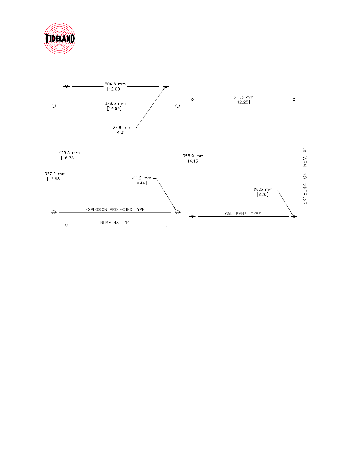
Enclosure:
Tideland GMU Version: ......Stainless steel enclosure with pre-drilled gland holes
Shipped with 2x 20 mm and 2x 25 mm glands
IP-67
See Figure 2 Mounting Dimensions
Explosion Protected Version:........................ Class I, Div. 1 & 2, Groups B1, C, D
Class I, Zones 1 & 2, Groups IIB+H2, IIA
Class II, Div. 1 & 2, Groups E, F, G
Class III, Div. 1 & 2
NEMA 3, 4, 4X2, 7(B, C, D), 9(E, F, G)
CENELEC/ATEX/IEC Ex
Ex d IIB + H2 T5 or T6
Ex tD A21 IP66

MAINTENANCE AND OPERATION MANUAL
TIBC-10 011.1255-00
Tideland Signal Corporation Page 3 of 14
0111255-00REVA_TIBC-10MANUAL20SEPT11.doc
Ta < +60°C
Enclosure predrilled with 3x 25 mm gland holes, plugged for shipment
See Figure 2 Mounting Dimensions
Note: No cable glands or bushings are provided with explosion protected
enclosure. All external wiring must comply with appropriate provisions of
local electrical codes.
Shipping Weight
Tideland GMU Version ................................................................ 17.3 kg (38.1 lb)
Explosion protected Versions ....................................................... 26.8 kg (59.0 lb)

MAINTENANCE AND OPERATION MANUAL
TIBC-10 011.1255-00
Tideland Signal Corporation Page 4 of 14
0111255-00REVA_TIBC-10MANUAL20SEPT11.doc
Figure 1 TIBC-10 Charger Panel View
MAINTENANCE AND OPERATION MANUAL
TIBC-10 011.1255-00
Tideland Signal Corporation Page 5 of 14
0111255-00REVA_TIBC-10MANUAL20SEPT11.doc
Figure 2 Mounting Dimensions

MAINTENANCE AND OPERATION MANUAL
TIBC-10 011.1255-00
Tideland Signal Corporation Page 6 of 14
0111255-00REVA_TIBC-10MANUAL20SEPT11.doc
2. Installation and Operation
2.1 Installation
Mounting hole locations and sizes are shown in Figure 2 Mounting Dimensions.
Before beginning the installation, make sure that the input and output settings meet your
particular requirements. The TIBC-10 is set at the factory according to the sales order. All
settings are marked on a label. An example label is shown in Figure 3 Configuration Label.
Figure 1 TIBC-10 Charger Panel View shows the overall layout inside the TBC-10.
If settings need to be changed, refer to section 2.4 Adjustment.
Figure 3 Configuration Label
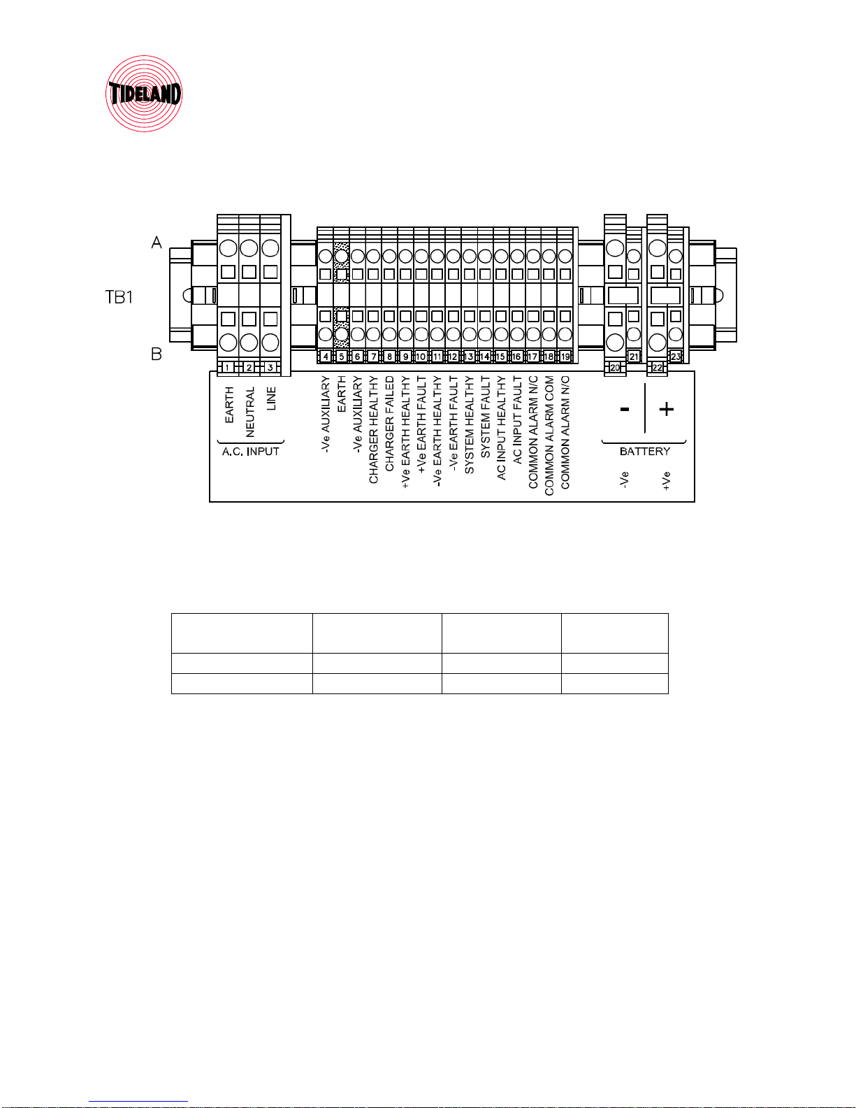
Once you have confirmed that the input and output voltages meet requirements, you may connect
the batteries and the input power to TB1. TB1 is shown in Figure 4 TB1 Details. Connect the
battery negative to TB1-20 and battery positive to TB1-22.
MAINTENANCE AND OPERATION MANUAL
TIBC-10 011.1255-00
Tideland Signal Corporation Page 7 of 14
0111255-00REVA_TIBC-10MANUAL20SEPT11.doc
Figure 4 TB1 Details
Connect the AC input using a standard 3 wire colour coding, per below table.
Wiring Standard Protective Earth,
TB-1
Neutral,
TB-2
Line,
TB-3
North American Green White Black
IEC Green-Yellow Blue Brown
Table 1 Standard Mains Color Coding
Input power may now be applied to operate the TBC-10.
2.1.1 Other connections
There are a number of status outputs that are indications of charger health and are made available
on the terminal block. These are outputs are referenced to Battery – and will drive 10 ma. when
energised. These outputs are tied to the LED indicators on the front panel (see Figure 1 TIBC-10
Charger Panel View).
NOTE: Excessive load on these outputs will affect the indicators on the panel and will give
false readings. Do not exceed 10 ma. load on any of these outputs.

MAINTENANCE AND OPERATION MANUAL
TIBC-10 011.1255-00
Tideland Signal Corporation Page 8 of 14
0111255-00REVA_TIBC-10MANUAL20SEPT11.doc
The outputs for individual status operate instantly when a fault is detected, or cleared. All alarms
self reset. The common alarm is activated when any of the individual faults are present, but the
relay is delayed for 120 seconds to minimize false alarms. Please note that the outputs and relay
are operated by battery power and will indicate correct status of AC mains faults.
Condition Monitored Action when Condition
Active
Corresponding LED
Indicator
LED Indicator
Colour
Charger Healthy Energised when
healthy
CHARGER
FAILED
GREEN
Charger Failed Energised when Failed CHARGER
FAILED
RED
DC +Ve Earth Fault
Healthy
Energised when
healthy
+Ve EARTH GREEN
DC +Ve Earth Fault
Alarm
Energised when earth
fault is detected
+Ve EARTH RED
DC –Ve Earth Fault
Healthy
Energised when
healthy
–Ve EARTH GREEN
DC –Ve Earth Fault
Alarm
Energised when earth
fault is detected
–Ve EARTH RED
System Healthy Energised when
healthy
FAULT GREEN
System Fault Energised when fault
detected
FAULT RED
AC Input Healthy Energised when
healthy
AC INPUT GREEN
AC Input Failed Energised when failed AC INPUT RED
Table 2 Status Outputs and LED Indicators
There is a Common Fault Alarm relay in the charger. The relay is normally energised when the
charger is operating normally (fail safe operation). This means that the normally open contacts
are closed when operating normally and open when a fault is detected. Normally closed contacts
are open when the charger is operating normally and close when a fault is detected.
2.2 Operation
Connect the charger to the battery first. When the TBC-10 is connected to a battery, there are
indicators that give the operating status of the charger. Indicators glow GREEN when the
charger is operating normally, and RED when a fault is detected. Please note that the indicators
are operated by battery power and will indicate correct status of AC mains faults.

MAINTENANCE AND OPERATION MANUAL
TIBC-10 011.1255-00
Tideland Signal Corporation Page 9 of 14
0111255-00REVA_TIBC-10MANUAL20SEPT11.doc
AC Mains power can be connected after the battery is connected. The charger will automatically
sense the charge state of the battery. Charge current will be supplied as needed to bring the
battery to full charge. The charge current is limited by initial setting (see Section 2.4 Adjustment
for instructions to set the output maximum current).
The charger is equipped with a cooling fan that is controlled by a temperature switch and
operates only when needed. The temperature switch is preset for 60°C and is not adjustable.
Please note that the fan is operated from the battery.
Indicators are described in Table 2 Status Outputs and LED Indicators.
The OUTPUT AMPS meter can be used to estimate the charge state of the battery. A low current
indicates the battery is charged or nearly charged. A higher current indicates charging. Charging
a deeply discharged battery may show the maximum current setting on the meter.
2.3 Testing
The charger is tested as follows:
i. With the battery disconnected, connect AC mains.
ii. Measure the voltage at the battery terminals. The voltage will be the same as the float
voltage configured into the charger (e.g. 13.7 volts).
iii. Disconnect AC mains. Connect a discharged battery.
iv. Reconnect AC mains. The OUTPUT AMPS meter should read the maximum output
current configured into the battery (e.g. 10 amps).
If there are any discrepancies with either the float voltage or output current values, the charger
should be adjusted.
2.4 Adjustment
The charger is adjustable for float voltage and output current. Once float voltage is set, all other
alarm settings are automatically set.
NOTE: These adjustments should be attempted only by qualified technicians.
WARNING!: Mains voltage is present. Isolate power before opening charger.
WARNING!: Incorrect connections and/or settings can cause the battery to fail in a
way to harm nearby personnel.

MAINTENANCE AND OPERATION MANUAL
TIBC-10 011.1255-00
Tideland Signal Corporation Page 10 of 14
0111255-00REVA_TIBC-10MANUAL20SEPT11.doc
CAUTION!: Incorrect settings can ruin the charger or the battery bank. Verify
settings.
There is an access panel on the charger. Remove the four screws holding the panel to the charger
and carefully move the panel out of the way. Figure 5 Adjustment Features shows the location of
the features that will be adjusted to set float voltage and charge current.
Figure 5 Adjustment Features
Connect the charger for adjustment per Figure 6 Adjustment Setup. If an electronic load is not
available, a discharged battery can be used in an alternative procedure, given below.
Start with the appropriate adjustment procedure to set the battery float voltage and maximum
current levels. During this procedure, please ignore alarms from the charger. The procedure in
2.4.3 Charger Alarm Level Calibration Procedure will establish correct alarm levels for the new
voltage and current settings.
i. Disconnect the AC mains supply and disconnect the battery.
ii. Make the connections as shown in Figure 6 Adjustment Setup, without the electronic
load and leave AC mains and battery disconnected.
iii. Connect the AC mains supply and adjust the float voltage (FLOAT) to the desired level
(e.g. 13.7 volts).
iv. Connect the battery.
v. Adjust the charger current (CURRENT) to the desired level (e.g. 10 amps).
vi. Disconnect AC mains.

MAINTENANCE AND OPERATION MANUAL
TIBC-10 011.1255-00
Tideland Signal Corporation Page 11 of 14
0111255-00REVA_TIBC-10MANUAL20SEPT11.doc
2.4.1 Adjustment Procedure with Electronic Load
i. Disconnect the AC mains supply and disconnect the battery.
ii. Make the connections as shown in Figure 6 Adjustment Setup, but leave AC mains and
battery disconnected.
iii. Set the electronic load for the desired charger output current (e.g. 10 amps), but leave the
load disabled.
iv. Connect the AC mains supply and adjust the float voltage (potx) to the desired level (e.g.
13.7 volts).
v. Enable the electronic load. Adjust the charger output current (poty) to the desired level
(e.g. 10 amps).
vi. Connect the battery.
vii. Disable the electronic load.
viii. Disconnect AC mains.
2.4.2 Adjustment Procedure with Discharged Battery
CAUTION!: Incorrect settings can ruin the charger or the battery bank. When setting
current, do not waste time, and set the current level promptly to avoid overheating either
the battery or the charger.
i. Disconnect the AC mains supply and disconnect the battery.
ii. Make the connections as shown in Figure 6 Adjustment Setup, without the electronic
load and leave AC mains and battery disconnected.
iii. Connect the AC mains supply and adjust the float voltage (potx) to the desired level (e.g.
13.7 volts).
iv. Connect the battery.
v. Adjust the charger output current (poty) to the desired level (e.g. 10 amps).
vi. Disconnect AC mains.
2.4.3 Charger Alarm Level Calibration Procedure
This procedure follows the either of the adjustment procedures above.
i. Disconnect the AC mains supply and disconnect the battery.
ii. Locate the PROG push button. Push and hold the PROG push button and reconnect the
AC mains supply.
iii. Wait for approximately ten seconds until each of the indicator LEDs are GREEN.
iv. Release the PROG push button.
v. Note that the LED’s will change colour during the internal calibration procedure.
vi. When all LEDs are GREEN, the internal procedure is complete.
vii. Disconnect the AC mains supply.
viii. Reconnect the battery and AC mains supplies.

MAINTENANCE AND OPERATION MANUAL
TIBC-10 011.1255-00
Tideland Signal Corporation Page 12 of 14
0111255-00REVA_TIBC-10MANUAL20SEPT11.doc
ix. Verify battery voltage is correct, and that all LEDs are GREEN.
Figure 6 Adjustment Setup
3. MAINTENANCE
3.1 Routine Maintenance
Since the TIBC-10 will always be used with a battery or batteries, the routine maintenance
required is mainly that required for the batteries.
•Check the electrolyte in the batteries periodically to ensure proper level.
•Check the connections at the batteries periodically to ensure that they are clean and tight.

MAINTENANCE AND OPERATION MANUAL
TIBC-10 011.1255-00
Tideland Signal Corporation Page 13 of 14
0111255-00REVA_TIBC-10MANUAL20SEPT11.doc
•Check the interconnecting cables between the TIBC-10, the batteries, and the load to
make sure that the insulation is in good condition and that the cables are not located in a
position where they are likely to be cut or broken.
•Check the TIBC-10 to make sure there is no water in the enclosure and there is no
corrosion on the terminals.
3.2 Field Service
The charger itself is not serviceable in the field. The charger can be replaced in the field (see
Figure 7 Exploded Diagram).
Please be sure that the charger is configured correctly for the battery it is to charge. Please check
that the circuit breaker is pushed-in and the output fuse is good.

MAINTENANCE AND OPERATION MANUAL
TIBC-10 011.1255-00
Tideland Signal Corporation Page 14 of 14
0111255-00REVA_TIBC-10MANUAL20SEPT11.doc
3.3 Exploded Diagram and Spare Parts List
Figure 7 Exploded Diagram
Spare Part Part Number Description
Fuse, 15 Amp ATC 181.1194-00 FUSE, ATC-15
Battery Charger 160.1021-00 BATT CHGR, TIBC-10 12/24V 10A
Fan Assembly, with
Temperature Switch
630.1387-00 FAN ASSY W/ TEMP SWITCH
Table 3 Spare Parts
Table of contents


