peblar WLAC1 Series Operating manual

EN: User and Installation Manual
NL: Gebruikers- en Installatiehandleiding

1
PEBLAR 2023
Table of contents
1USER MANUAL .................................................................................................................. 2
1.1 Introduction .................................................................................................................................................... 2
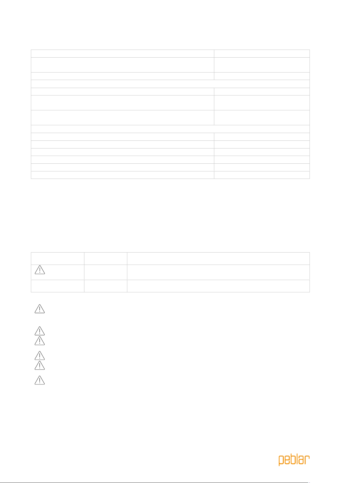
1.2 Safety and usage information...................................................................................................................... 2
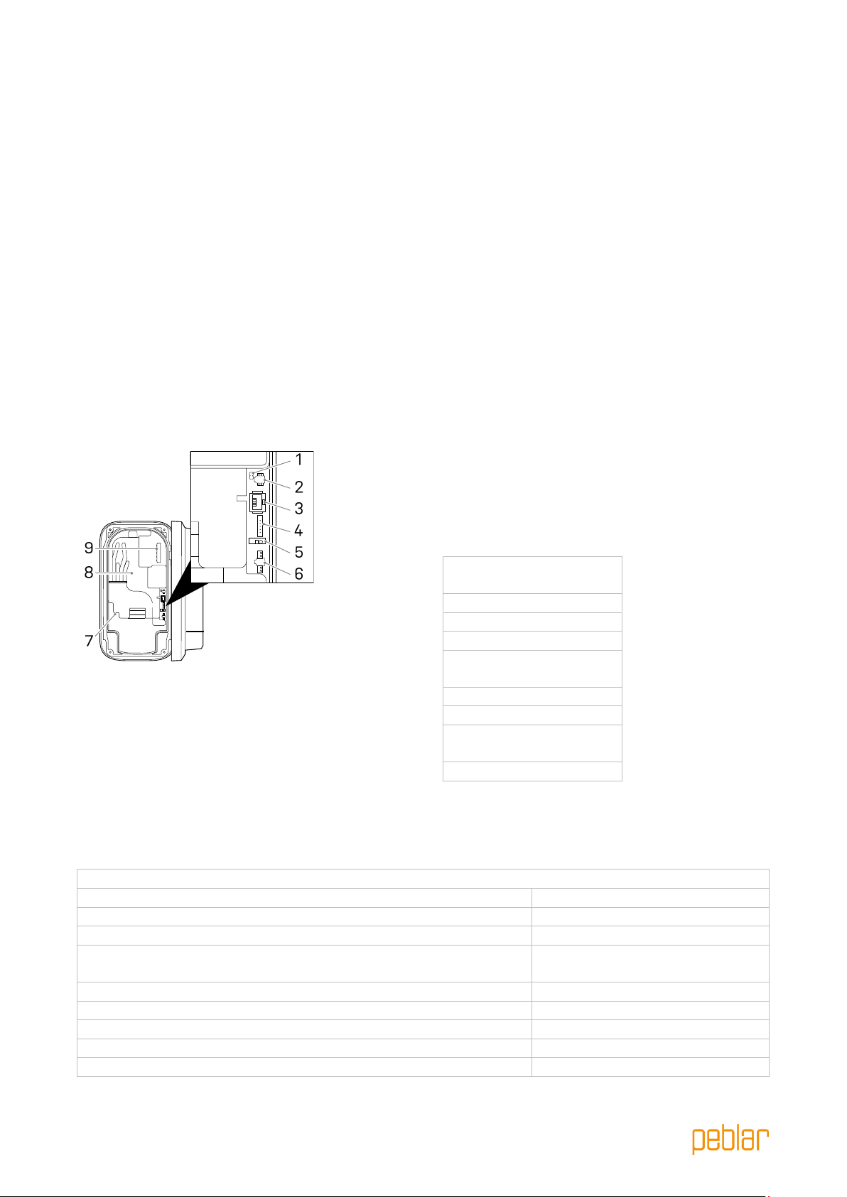
1.3 Product information ...................................................................................................................................... 3
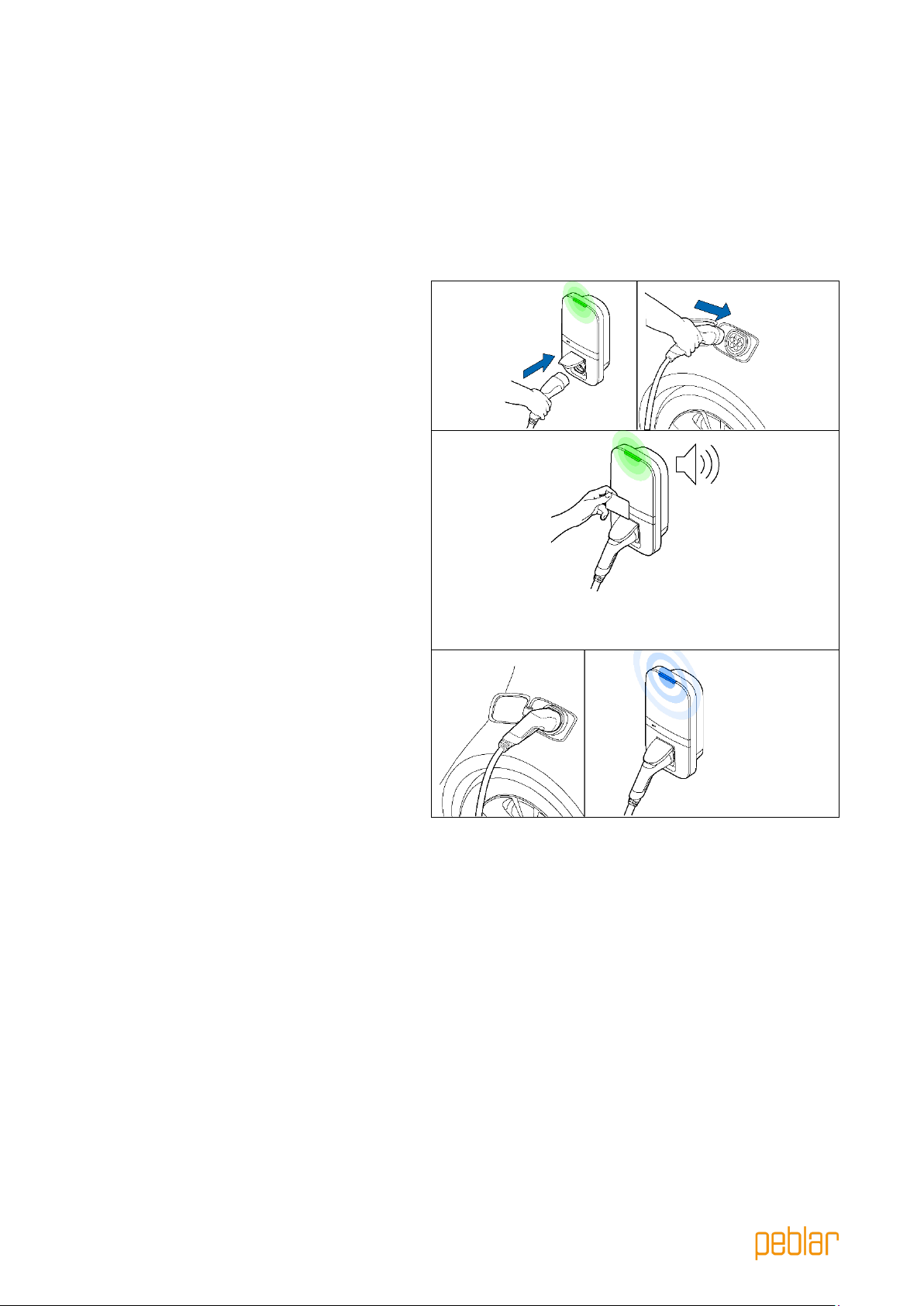
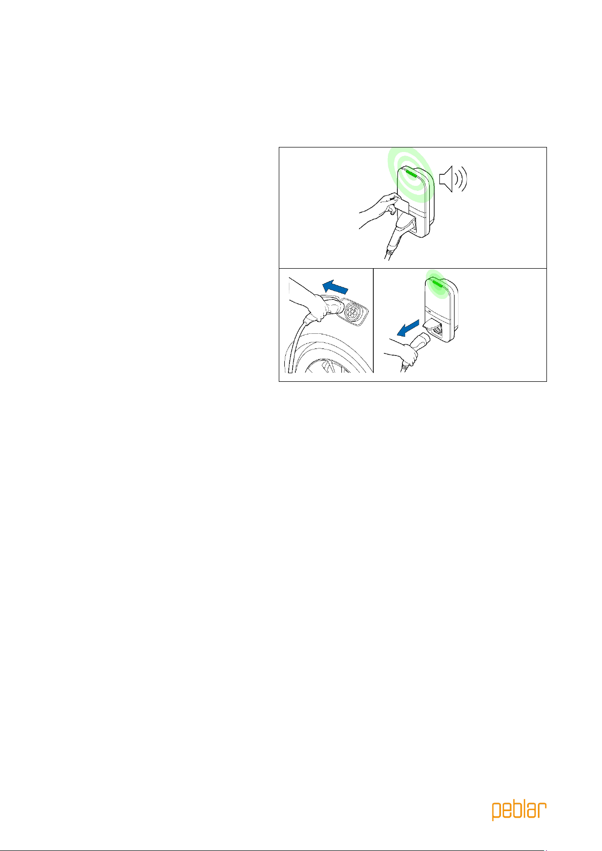
1.4 Charging your vehicle.................................................................................................................................... 5
1.5 Product configuration ................................................................................................................................... 6
2INSTALLATION MANUAL ............................................................................................... 7
2.1 Introduction .................................................................................................................................................... 7
2.2 Product information ...................................................................................................................................... 7
2.3 Safety instructions......................................................................................................................................... 9
2.4 Installation ................................................................................................................. 10
2.5 Commissioning ........................................................................................................... 22
2.6 Decommissioning .........................................................................................................................................23
2.7 Transportation, storage ..............................................................................................................................24
2.8 Disposal..........................................................................................................................................................24
APPENDIX A: MODEL IDENTIFICATION STRING........................................................ 25
APPENDIX B: TROUBLESHOOTING................................................................................ 25
APPENDIX C: EU - DECLARATION OF CONFORMITY .............................................. 27
APPENDIX D: GLOSSARY.................................................................................................. 27

2
PEBLAR 2023
1User manual
1.1 Introduction
This part of the manual explains the use of the charger for the user. It is important that the user
reads the safety and usage information before using the charger.
Used symbol
Definition
Explanation
WARNING
Potential hazardous situation which, if not avoided, could result
in death or serious injury.
Attention
Risk of undesired behavior of the charger
1.2 Safety and usage information
The charger is intended exclusively for charging electric vehicles. Read and follow the safety
precautions before using the charger. A qualified installer must ensure that the charger is installed in
accordance with the relevant country-specific standards and local regulations. Retain this manual for
future reference.
WARNING: The electrical supply must be switched off before the front assembly is opened or
any installation, maintenance or repair work is undertaken.
WARNING: Using this product is prohibited near flammable substances.
WARNING: Do not use the charger or charging cable when it is damaged.
Attention: Only use the charger at temperatures between -30 and +50 degrees Celsius.
Attention: Place the protective cap on the vehicle connector when not using the charger.
Attention: Do not apply excessive force on the charging cable.
Attention: Do not leave the vehicle connector of the charging cable on the ground.
Attention: Only clean the charger with a dry cloth. Do not use aggressive cleaning brands Do
not use a pressure washer.
Attention: This product should be used with a minimum distance of 25 cm to your body.
Attention: Do not use adapter plugs with the charger.
Attention: Do not use extension cords with the charger.
Attention: Do not remove or adjust any markings, warning symbols or the label of the
charger.

3
PEBLAR 2023
1.3 Product information
Socket Fixed cable
Parts overview
The table below explains the numbered items in the figure.
1. LED status indicator
4. Label
2. RFID scanner
5. Type 2 charging cable*
3. Display (optional)
6. Type 2 socket*
* either the socket or the charging cable is present
On the label (4), the model type is printed. This provides information about the applicable features of
the charger, which are further explained for all charger variants in Appendix A.
Status indication
The table below shows the options for the top LED status indicator (1).
LED feedback
Charger status
Yellow
Start-up / not commissioned / unavailable
Green
Ready to use, no EV connected / EV connected, but not authorized
Blue
Authorized
Pulsating blue
Charging
Blinking red
Error detected. See Appendix B for troubleshooting

4
PEBLAR 2023
Display
Optionally the charger is equipped with a display to present energy metering information from the
current charging session with a resolution of 0.01 kWh. The figure below explains the information.
1. Charging or discharging
2. Energy charged current session / total energy charged over lifetime / costs of the charging
session / energy tariff
3. Indication for energy tariff displayed
4. Unit of displayed number, kWh, €, or €/kWh
5. Indication whether displayed energy corresponds to current session or total energy over lifetime

5
PEBLAR 2023
1.4 Charging your vehicle
Attention: Unwind the charging cable completely when charging your vehicle.
Start charging your vehicle
The charger is ready for charging when the
LED status indicator is green. Plug the
charging cable into the socket (if applicable)
and into your electric vehicle.
Hold your RFID card/tag in front of the
reader to start charging. The status LED
flashes green for a second and a beep is
emitted when the RFID card/tag has been
read. If the charger has a socket, the cable
will now be locked to the charger.
For automatic starting of charging the RFID
authorization can be disabled (see section
1.5)
The vehicle is being charged; the LED status
indicator is pulsating blue. This might take a
few seconds.

6
PEBLAR 2023
Stop charging your vehicle
Attention: Do not pull the charging cable when unplugging; pull the connector of the
charging cable instead.
Hold your RFID card in front of the reader to
stop charging. The LED status flashes green
for a second and the charger emits a beep
when the RFID card/tag has been read.
The session is now finished.
Unplug the charging cable from your electric
vehicle. If the charger has a socket the
charging cable can be unplugged from the
charger.
1.5 Product configuration
Connect to the WLAN access point of your charger using e.g. a phone or laptop. The network
hostname SSID and password are printed on the label on the back of the supplied manual or quick
start guide. The QR code on this label can also be scanned with a mobile phone to connect to the
charger’s access point.
Another way to reach the web interface is to plug in an ethernet cable into both your computer and
the charger.
Browse to the hostname in your browser and log in to the web interface using the password provided
with the charger, located at the back of the supplied manual or quick start guide. In the dashboard,
multiple settings can be adjusted or observed. The web interface will explain the definition of these
settings.

7
PEBLAR 2023
2Installation manual
2.1 Introduction
This part of the manual describes how to install the charger. It is important that you read the safety
instructions before you start.
Intended audience.
The installation manual is intended exclusively for qualified installers who can assess the work and
identify potential danger.
2.2 Product information
Interface overview
The table below lists all possible connectors on
the charger. Consult the identification string in
Appendix A to see what is present in the
charger.
1. BUS termination
jumper*
2. BUS connector*
3. Ethernet connector*
4. Socket connector*
5. Control pilot
connector*
6. CT coils connector
7. SIM card holder*
8. Energy meter
accuracy LED*
9. Mains connector
* Optional
Specifications
The table below lists the detailed specifications of this product. Note that not all specifications may
apply to the charger. The model identification string in Appendix A determines the applicable
specifications.
General
Charger type
IEC 61851 AC mode 3
EV plug / socket connection
IEC 62196 Type 2
Rated output current (depending on variant)
16 A or 32 A
Rated voltage
230 V AC (1-phase) or 400 V
AC (3-phase)
Nominal power
Up to 22 kW
Rated frequency
50 Hz
Dimensions (H x W x D, ex. cable)
387 x 207 x 128 mm
Weight (excl. cable)
Approx. 2.9 kg
Charge cable length
4.5 m, 5 m or 7.5 m

8
PEBLAR 2023
User interface
Multicolor LED, buzzer, display
Ventilation (IEC 61851 state D)
Not supported
Intended use
Residential, commercial, and
industrial applications
Safety
Current leakage protection
6 mA DC earth leakage
protection
Safety class
Class I
Overvoltage category
Category III
Disconnection prevention socket
Locking mechanism
Authorization
Authorization methods
RFID (Mifare classic & Mifare
DESfire), Plug and Charge
(ISO15118)*
Energy meter
Energy meter class
Class B
Certification (depending on variant)
MID
Mess & Eichrecht (DE)
Environmental
Operating temperature
-30 C to +50 C
Ambient storage temperature
-40 C to +85 C
Relative humidity range
5% to 95%
Maximum operating altitude
3000 m
IP rating
IP54
IK rating
IK10
Connectivity
WLAN
2.4 GHz with WPA2
Fixed network
Ethernet 100 Mbit
Cellular
LTE Cat-M1, NB-IoT, GPRS
SIM size
Nano-SIM (4FF)
Frequency bands
Technology
Band
Maximum radiated output
Power (dBm)
(E)GPRS
900
36
(E)GPRS
1800
33
LTE
1
23.7
LTE
3
23.7
LTE
8
23.7
LTE
20
23.7
LTE
28
23.7
802.11b/g/n
2400
19.99
Supported protocols
Vehicle communication
IEC 61851-1
ISO 15118-2*
ISO 15118-20*
Back-end communication
OCPP 1.6J (including security
whitepaper)
OCPP 2.0.1*
Firmware update
Locally via web interface
Over-the-air via OCPP
Blackout protection / load balancing

9
PEBLAR 2023
Static
Configurable current limit
Dynamic
Hardwired via CT coils
P1 Dongle
Group load balancing
RS-485 (leader or follower)
Installation
Installation location
Indoor and outdoor usage
Mains connection
Permanent mains connection
only
Installation type
Stationary equipment. Wall or
pole mounted
Recommended installation cable use**
3-phase 22kW, cable length: <25M
5x4mm2
3 phase 22kW, cable length: >25M
5x6mm2
3-Phase 11kW, cable length <25M
5x2.5mm2
3-Phase 11kW, cable length >25M
5x4mm2
1-Phase 7kW, cable length <25M
3x4mm2
1-Phase 7kW, cable length >25M
3x6mm2
* Hardware prepared
** Check local installation requirements
2.3 Safety instructions
Read and follow the safety instructions below. Incorrect installation, repairs or modification can result
in danger and may void the warranty.
Used symbol
Definition
Explanation
WARNING
Risk of failure of the charger
Attention
Risk of undesired behavior of the charger
WARNING: The installation must be carried out by a qualified installer who has read this
manual. Failure to follow the instructions in this manual may result in serious injury or
death.
WARNING: Switch off the mains input power before installing the charger.
WARNING: Keep the power off until the charger is installed, and you have reached step
11 in the instructions list.
WARNING: Do not install a faulty or damaged charger.
WARNING: Do not install the charger in wet weather conditions or when the humidity
exceeds 95%.
An upstream circuit breaker (MCB) and residual current device (RCD) must be installed.
The MCB (characteristic B or C) shall have a current rating in accordance with the local
mains supply and required charge current (max 32A). The RCD shall be type A (30 mA)
or type B (30mA) depending on local regulations.
Attention: Check local installations standards for additional requirements.

10
PEBLAR 2023
2.4 Installation
Contents of the box
Number
Definition
Size
Quantity
P1
Bottom cover
-
1
P2
Top cover
-
1
P3
Screw for front assembly/charging cable*
M4x10 mm
6 (+5*)
P4
Front assembly
-
1
P5
Base assembly
-
1
P6
Charging cable*
4.5, 5 or 7.5 m
1
P7
Screw for charging cable*
3x10mm
2
P8
Charger template
-
1
P9
Manual/quick start guide
-
1
P10
RFID card**
-
1
P11
Mounting ring
-
1
P12
Rear wall countersunk screw
5x60 mm
1
P13
Rear wall pan head screw
5x50 mm
2
P14
Wall plugs
8 mm
3
P15
Cable gland nut
M32
1
P16
Cable gland
M32
1
P16a
Cable gland reduction insert
-
1
P17
Grommet for peripherals
M25
1
P18
Grommet for mains cable
M32
2
P19
Cable tie for peripherals/charging cable
-
4(+3*)
P20
SIM card**
-
1
P21
CT coils**
-
1 (1-phase)
3 (3-phase)
P22
Distribution block for CT coils**
-
1
P23
BUS termination jumper
-
1
* Cable variants
** Optional

11
PEBLAR 2023
Required tools
Number
Definition
Size
1
Power drill
-
2
Drill bit
8 mm
3
Spirit level
-
4
Cable stripper
5
Cable cutter
-
6
Wire stripper
-
7
Wire stripper
2 mm
8
Ethernet crimping tool
9
Torx screwdriver
T10
10
Torx screwdriver
T20
11
Torx screwdriver
T30
12
Adjustable wrench
-
13
Pencil
-

12
PEBLAR 2023
Step 1: Choose charger location
-Install the charger in a location that allows
the charge cable to reach the vehicle
charge port without putting strain on the
cable.
-Avoid installation in direct sunlight for
optimal performance of the charger.
-The recommended free space around the
charger is >=300 mm.
-The recommended height of the mounting
ring is 1400 mm.
-When the charger is equipped with a fixed
cable, the lowest point of the vehicle
connector when stored shall be located at
a height between 0,5m and 1,5m above
ground level.
-Check local accessibility regulations.
Attention: The wall must have a flat structure and must be able to hold a sufficient load.
This installation procedure is meant for a concrete or brick wall. If another mounting
surface is used, ensure that appropriate screws and/or plugs are used.
Step 2: Select the hole where the mains
cable should enter the charger
The two holes indicated with numbers H1 and
H2 can be used for inserting the mains cable.
Select the hole where the mains cable should
enter the charger.
When the back hole is selected (indicated with
H1 in the figure) follow steps 3-4. When the
lower hole is selected (indicated with H2 in the
figure) follow steps 5-6 on page 18.

13
PEBLAR 2023
Step 3: Back hole –preparation
-Use the cardboard template (P8)and a
spirit level to mark the holes for the
mounting screws and mains cable.
-Drill three 8 mm holes at the marked
locations.
-Insert plugs (P14) into the drilled holes.
-Tighten the mounting ring (P11) with
countersunk screw (P12) to the upper plug
in the wall.
Attention: The mounting
ring is assymmetric. The
flat end must be placed
against the wall
Step 4: Mounting the base assembly
-Strip the mains cable at 30 mm from the
wall.
Attention: Keep the
cables at least 200 mm
long so you can cut
them to the desired
length later.
-The front assembly (P4)and the base
assembly (P5)can be detached from each
other.
-You can detach the two parts by
disconnecting the connector (1) from the
front assembly.
Attention: Make sure
that the mains cable
entry matches, and is
centered, to the back
hole in the template

14
PEBLAR 2023
-Insert the grommet (P18) in the bottom-
right hole (H2).
-Insert the grommet (P17) in the bottom-
left hole (H3).
Attention: Ensure that grommets are
inserted correctly, to guarantee
resistance to ingress of water and dust.
-Create a hole in the center of the grommet
(P18) and insert the grommet in the back
hole.
-Push the mains cable (1) through the
grommet located in the back.
-Attach the base assembly to the mounting
ring (P11) and press down firmly.
-Put the two pan head screws (P13) loosely
trough the bottom mounting holes, level the
base assembly and tightening the screws.
-Cut off the power cables at the right length
to push them in the DIN rail terminal block
(1).The route of the cables should be as
short as possible.
-Strip the power cables at 10 mm.
Go to step 7 on page 20.
Step 5: Lower hole –preparation
-Use the cardboard template (P8) and a
spirit level to mark the holes for the
mounting screws and mains cable.

15
PEBLAR 2023
-Mark and strip the mains cable at 10mm
above the mains wire entrance as indicated
on the template.
Attention: Make sure
that the mains cable
matches, and is centered
to the right dotted line on
the template.
-Drill three 8 mm holes at the marked
locations.
-Insert plugs (P14) into the drilled holes.
-Tighten the mounting ring (P11) with
countersunk screw (P12) to the upper plug
in the wall.
Attention: The mounting
ring is assymmetric. The
flat end must be placed
against the wall
Step 6: Lower hole –Mounting the base assembly
-The front assembly (P4)and the base
assembly (P5) can be detached from each
other.
-You can detach the two parts by
disconnecting the connector (1) from the
front assembly.
-Insert the grommet (P18) in the back hole
(H1).
-Insert the grommet (P17) in the bottom-
left hole (H3).
-Place the cable gland nut (P15) above the
bottom-right hole (H2) and fasten it with
the cable gland (P16) at 10 Nm using the
adjustable wrench.
-Only for a mains cable with a diameter of 9
–14mm place the reduction insert (P16a)
into the cable gland.

16
PEBLAR 2023
Attention: Ensure that grommets and the cable gland are inserted correctly, to
guarantee resistance to ingress of water and dust.
-Insert the mains cable (1) in the cable gland
sealing nut and base assembly. Do not yet
secure the sealing nut.
-Attach the base assembly to the mounting
ring (P11) and press down firmly.
-Put the two pan head screws (P12) loosely
trough the bottom mounting holes, level the
base assembly and tightening the screws.
-Fasten the cable gland sealing nut with 10
Nm using the adjustable wrench.
-Cut off the power cables at the right length
to reach the DIN rail terminal block (1). The
route of the cables should be as short as
possible.
-Strip the power cables at 10 mm.
Attention: Ensure that the power cables are located right from the bracket (2).
Step 7: Mains connection
-When installing multiple chargers on one grid connection, check 7a
-When installing the charger in a IT grid (three phase without neutral), check 7b
-Connect the power cables for L1, L2*,
L3*, PE and N to the correct DIN rail
terminal block push-in connector in the
base assembly.
* only present in three-phase variant of the
charger
The figure indicates which push-in connector
corresponds to the phase, neutral or ground.
Attention: Do not connect the phase cables L1, L2 or L3 in the PE or N connectors.
Step 7a: Phase rotation
It is essential to rotate the phases when connecting multiple chargers on one grid connection, to
evenly distribute the load and prevent phase unbalance. The figure below shows the different names of
the phase rotations. Phase 1 is indicated with an ‘R’ (rotary), phase 2 with an ‘S’ (secondary) and
phase 3 with a ‘T’ (tertiary).

17
PEBLAR 2023
Attention: Write down the name of the phase rotation you
apply, as you need it later during commissioning of the
chargers.
Recommended order for the connection:
Charger 1
Charger 2
Charger 3
Charger 4
Charger 5
Charger 6
Etc.
RST
(=L1L2L3)
STR
(=L2L3L1)
TRS
(=L3L1L2)
RST
(=L1L2L3)
STR
(=L2L3L1)
TRS
(=L3L1L2)
…
Step 7b: IT grid 3x230 V
-When an IT-grid (three phase 230 V
without neutral) applies, connect the cables
as indicated. L3 on charger side remains
free.
Attention: Only use this diagram after
checking the current of 230 V between
phases. Connecting any other grid
system according to this diagram will
lead to permanent damage to the
charger.
Step 8: Install charging cable*
* Optional
-Attach the strain relief of the charging
cable (P6)to the front assembly using the
two screws (P7)at 1.1Nm.
-Route the cables underneath the notch (1)
and mount the power cables with the
screws (P3)to the correct phases (L1, L2,
L3), neutral (N) and ground (PE) at 2 Nm,
as indicated in the figure.
-Insert the white CP cable in the CP push in
connector on the board (2).
-Secure the power cables with cable ties
(P19).
Attention: Connect the phases, neutral and protective earth with the correct connector
in the cover. The correct order is indicated on the cover: PE –L3 –N –L2 –L1

18
PEBLAR 2023
Step 9: Install peripherals
-Attach the front assembly
(P4)to the base assembly
(P5).
Attention: It is recommended to use a shielded Cat-5 (or
higher) cable for connecting the peripherals to the charger.
Ethernet*
-Make a hole in the
grommet for peripherals
(P17).
-Push the Cat cable through
the grommet.
-Strip the cable and attach
an RJ-45 ethernet
connector (2).
-Plug the ethernet cable in
its connector (1).
-Secure the cable using
cable ties (P19).
Install load balancing kit with CT coils*
The load balancing kit is mostly used in home applications, to prevent potential blackouts. When the
power usage of the house is high, and the vehicle is charging at the same time, the load balancing
feature will lower the charging current in these situations.
Attention: Connecting the signal wires of the CT coils
incorrectly may cause the charger to exceed the configured
charging current.
Attention: It is recommended to use a shielded Cat-5 (or
higher) cable. The maximum length of this cable is 150
meters.

19
PEBLAR 2023
-Mount the CT coil(s) (P21)
over the phase cable(s) (1)
in the fuse box in the house
right after the main switch.
-When opening the CT coils,
you might see an arrow. (If
there is no arrow, the
direction does not matter)
This arrow defines the
direction of the current in
the fuse box. Place the coil
over the phases in the
correct direction for correct
measurements.
-Attach the wires of the CT
coil(s) to the distribution
block (P22).
-Connect the wires of a
signal cable (2) to the
corresponding pins in the
distribution block. Label
which cable belongs to
which polarity of the CT coil.
-Secure the distribution
block to a suitable place in
the fuse box.
-Cut an (additional) hole in
the grommet placed for
peripherals (P17) and push
the signal cable through the
hole in the grommet.
-Strip the signal cable and
its wires (2).
-Connect the signal wires to
the push-in connector for
dynamic load balancing (1),
indicated with CT. The
figure displays the
connector definition per pin.
-Secure the cable using a
cable tie (P19)
This manual suits for next models
1
Table of contents
Languages: