TigerStop TS Series Instruction Manual

TigerStop
Installation & User Manual


iii
Table of Contents
1 Contact Us
2 Parts Inventory
6 TigerStop Installation
6 ElEctrical rEquirEmEnts
6 tigErstop anatomy
7 mounting tigErstop
7 attach thE Flip-away stop
8 mini gangstop installation
9 standard intErconnEct Kit installation
11 controllEr stand
12 Final connEctions
13 Setup
13 homE routinE
13 rEady scrEEn
14 sEt ZEro End
15 run thE drivE tEst
15 Find thE End limits
16 sEt units
17 calibratE tigErstop
17 KErF
18 sEt intErconnEct typE
19 optimiZEr sEttings
21 TigerStop®Standard Controller Basic Functions
21 manual movEmEnt
21 calculator modE
22 incrEmEnt
23 Jog
23 quicK calibration
23 prEsEt
25 part lists
31 bacKboard dEFEcting & optimiZing
33 disablE quicK calibration
35 Maintenance Schedule
36 Maintenance Log
37 Appendix A: Default Parameter Values
39 Appendix B: Accessories & Software

iv
SAFETY FIRST!
IMPORTANT SAFETY INFORMATION. READ ALL WARNINGS BEFORE OPERATING THIS PRODUCT.
WARNING: Installation of your TigerStop® Product must be done by a person trained in the safe design and installation of
automation products, and in the safe operation of power equipment. Ensure that such installation meets all legally required
safety requirements and guidelines, and that proper guarding and safety devices are provided on all sides of the equipment to
preclude unintended access during operation. Consult with and follow the recommendations of a qualified safety engineer.
WARNING: TigerStop® Products are components intended for use in conjunction with potentially dangerous machinery.
The use of TigerStop® Products does not make other machinery safe. TigerStop® Products are not intended to substitute,
in any manner, for safe operating practices in general, or for safety features present in other machines designed to make
those machines as safe as possible. TIGERSTOP® PRODUCTS, IF USED OR INSTALLED IMPROPERLY, MAY CAUSE
PERSONAL INJURY OR DEATH AND SHOULD ONLY BE OPERATED BY PERSONS TRAINED IN THEIR SAFE OPERATING
PROCEDURES. Illustrations of TigerStop® Products in use do not show, and are not intended to show, all safety features and
practices necessary for their safe operation.
WARNING: TigerStop® Products must be installed in accordance with all local, state, and federal regulations. Only personnel
properly trained in the safe design and installation of automation machinery and related power equipment should install
TigerStop® Products onto other equipment, to ensure a safe and proper work station. TigerStop® Products should not be
operated without proper training, both in the operation of TigerStop® Products, and in the operation of related equipment.
IMPORTANT CAUTION:
The motor box (compartment) contains DC voltage with potentially FATAL amperage. NEVER attempt any unauthorized actions
inside the motor box.
WARNING: Using a TigerStop® interconnect does not relieve you of the responsibility for making sure that your saw or other
tool has all the necessary safety equipment in place. All installations must meet all legally required safety requirements and
guidelines. Installation and training should be done following the recommendations of a qualified safety engineer.
DANGER: This machine can start, move and stop automatically. Keep hands and loose clothing clear of moving parts while
operating. Moving parts can crush and cut. When used with a saw or other cutting equipment, bodily injury and death may result
if operated without safety guards on all machines. Do not operate with guards removed. Operators must wear adequate eye and
ear protection.
GENERAL WARNINGS
INSTALLATION WARNINGS
INTERCONNECTS
OPERATION
v
IMPORTANT SAFETY INFORMATION. READ ALL WARNINGS BEFORE OPERATING THIS PRODUCT.
DANGER! Don’t get pinched by the push feeder. Keep your hands away when in motion!
Keep the work area clean and well lighted to avoid accidental injury.
Do not operate near flammable liquids or in gaseous or explosive atmospheres!
Use only 3-wire extension cords that have 3-prong grounding type plugs and 3-pole
receptacles that accept the tools plug for 120VAC. Use only 5-wire cords and plugs
when using 3 phase.
Do not open motor compartment or controller keypad. DC Voltage with potentially
FATAL amperage! Disconnect power before servicing. No user-serviceable parts inside.
DO NOT operate this or any machine under the influence of drugs or alcohol!
No one should operate this machine except for fully qualified personnel.
READ THE MANUAL!
Do not use TigerStop® machines in a dangerous environment. Using power tools in damp
or wet locations or in rain can cause shock or electrocution.
Wear proper apparel, no loose clothes, long hair or jewelry which could get pulled into
moving machinery or materials. Wear non slip footwear, safety glasses, ear protection
and a dust mask.

vi
Enable your TigerStop
Tig e rSTo p won’Tfu n cTion u nTil iT i S enab le d .
wHaT iS MY paSSword?
1. Fill out the warranty registration form and send it to TigerStop®
Customer Service via email at service@tigerstop.com or fax it to (360)
260-0755.
2. TigerStop®Customer Service will email you the enable code during
business hours, Monday-Friday 6am-4pm PST. You can also request
the code by phone.
3. After installing TigerStop, power it on and the screen displays: “Enter
Enable Code…Call TigerStop®…ph# 360-254-0661” and the machine
serial number in the format “SN=#######”.
4. Enter the enable code and press to load it.
The TigerStop’s password is set to the serial number.

1
TigerStop®technical support on the web, including manuals and videos:
TigerStop®customer service and technical support by email:
TigerStop®customer service and technical support by phone:
Contact Us
https://www.tigerstop.com/service-center/
service@tigerstop.com (Americas, Australia)
sos@tigerstop.nl (Europe)
1 (360) 448 6102 (Americas, Australia)
00 31 546 575 171 (Europe)

2
Parts Inventory
PART DESCRIPTION
(NUMBER) QUANTITY
TigerStop Beam &
Carriage
(TS-##)
1
Amplifier
(AMP6) 1
TigerStop® Standard
Controller
(CON5)
1
Standard Interconnect
Kit
(SIK)
1
Power Cable
(PC) 1
Data Cable
(CC5-XX) 1
Installation Hardware
Pack
(F0033)
*Includes optional weld nuts
1
Main aSSeMblY
3
Parts Inventory
PART DESCRIPTION
(NUMBER) QUANTITY
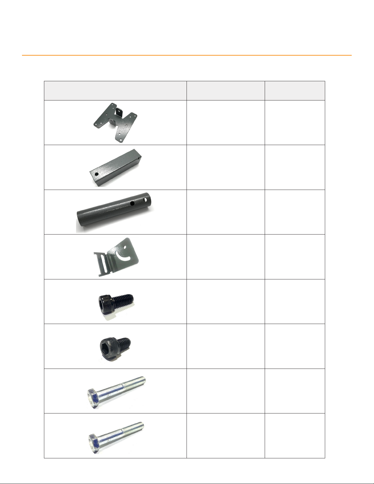
Controller Stand Top
(M1803) 1
Square Tube
(M1808) 1
Round Tube
(M1807) 1
Controller Stand
Base Half-Bracket
(M10070)
2
M6x14mm
Socket-Head Screw
(F7216)
1
M6x10mm
Socket-Head Screw
(F7208)
1
M8x50mm
Hex-Head Screw
(F9827)
1
M8x45mm
Hex-Head Screw
(F9826)
2
conTroller STand aSSeMblY

4
Parts Inventory
PART DESCRIPTION
(NUMBER) QUANTITY
Spacer
(F6702) 1
M8x35mm
T-Bolt
(F0184)
2
M8
Flange Nut
(F0419)
5
PART DESCRIPTION
(NUMBER) QUANTITY
Flip-Away Stop
(STOP2) 1
M12 Threaded Rod
(M1405-2) 1
M12 Locking Nut
(F2031) 2
1/2” Nylon Washer
(F1700) 2
flip-awaY STop aSSeMblY

5
Parts Inventory
Mini gangSTop
PART DESCRIPTION
(NUMBER) QUANTITY
Retention Block
(XMA4720) 2
Locking Handle
(LH) 2
M6 Hex Nut
(F2004) 2
M8x10mm Cap Screw
(F1935) 2
M8 Weld Nut
(F0406) 2
Stop Bar Tube & Plate
(M1021 & M4720-1) 1
PVC Foot
(B4700-2) 1
#10-14x1” Thread-forming
Screw
(F5004)
2
6
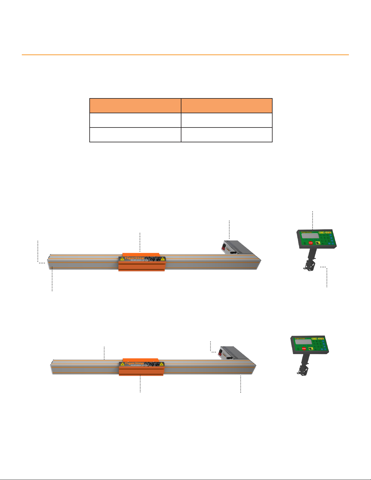
TigerStop Installation
Controller
Controller
Stand
Motor Box
Flip away Stop
End Cap
TigerStop
Serial Number
Power Switch
&
Incoming Power
Attachment
Mounting Slots
Orange
Trim Strips
TigerStop
Mounting Slots
(Underside)
elecTrical requireMenTS
power
TigerStop requires a dedicated circuit.
VOLTS CIRCUIT BREAKER
110V 15A
208/240V 20A (USA)/16A (EU)
TigerSTop anaToMY

7
TigerStop Installation
T-Bolt
Washer
Lock Washer
Nut
1. Place TigerStop on the mounting surface
with the motor box vertically up.
2. Insert the M8x35mm T-Bolts from the
hardware pack into the TigerStop’s 2
mounting slots. Space each pair of T-bolts
about 2’ (610mm) apart along the length of
the beam.
3. Rotate TigerStop so that the T-Bolts go
through the holes in the mounting surface
and the motor box is outside of the tool’s
feed path.
4. Attach the M8 Flat Washer, M8 Locking
Washer, and M8 Hex Nut on each T-Bolt, in
that order. Finger tighten the bolts.
5. Starting from the end closest to the tool,
align the beam with the tool’s back fence.
Tighten the bolts 1/4-turn past finger-tight.
6. Continue checking alignment and tightening
bolts until reaching the end of the beam.
MounTing TigerSTop
aTTacH THe flip-awaY STop
1. Align the through-holes of the Flip-Away
Stop with the TigerStop’s Carriage.
Carriage

8
Nylon Washer Nylon Washer
Locking Nut Locking Nut
Threaded
Rod
2. Insert a 1/2” Nylon Washer on each end
between the Carriage and the through-
holes of the Flip-Away Stop.
3. Insert the M12 Threaded Rod through the
Carriage and Flip-Away Stop.
4. Screw the M12 Locking Nuts on each
end of the M12 Threaded Rod. Tighten
until the Flip-Away Stop holds its position
when raised to a 45° angle.
TigerStop Installation
Mini gangSTop inSTallaTion
1. Attach the PVC Foot to the Mini
GangStop’s Plate with two #10-14x1”
Thread-forming Screws.
Set Screws
5. Adjust the Set Screws to make the
Flip-Away Stop level with the mounting
surface.

9
3. Connect the 2 Retention Blocks
to the M8 Weld Nuts using the
M8x10mm Cap Screws. Insert the
Locking Handles through the Rention
Blocks and secure with the M6 Hex
Nuts.
4. Slide the Mini GangStop assembly
into the Retention Blocks with the
PVC Foot towards the tool. Tighten
down the Locking Handles.
TigerStop Installation
2. Slide 2 M8 Weld Nuts into the lower
channel of the Flip-Away Stop.
STandard inTerconnecT KiT inSTallaTion
liMiT SwiTcH fu ncTi o n
The limit switch tells TigerStop the tool’s current status.
Integrate the tool and TigerStop with the Limit Switch and Air Solenoid to enable safer semi-automatic operation
when running Part Lists.
• Tool Cycling: Opens the Limit Switch and TigerStop cannot move.
• Tool at Rest: Closes the Limit Switch and TigerStop is free to move.
10
TigerStop Installation
For non-pneumatic tools, the 24V of the Air Solenoid are capable of driving an electronic relay to the same
eect. Some wiring required.
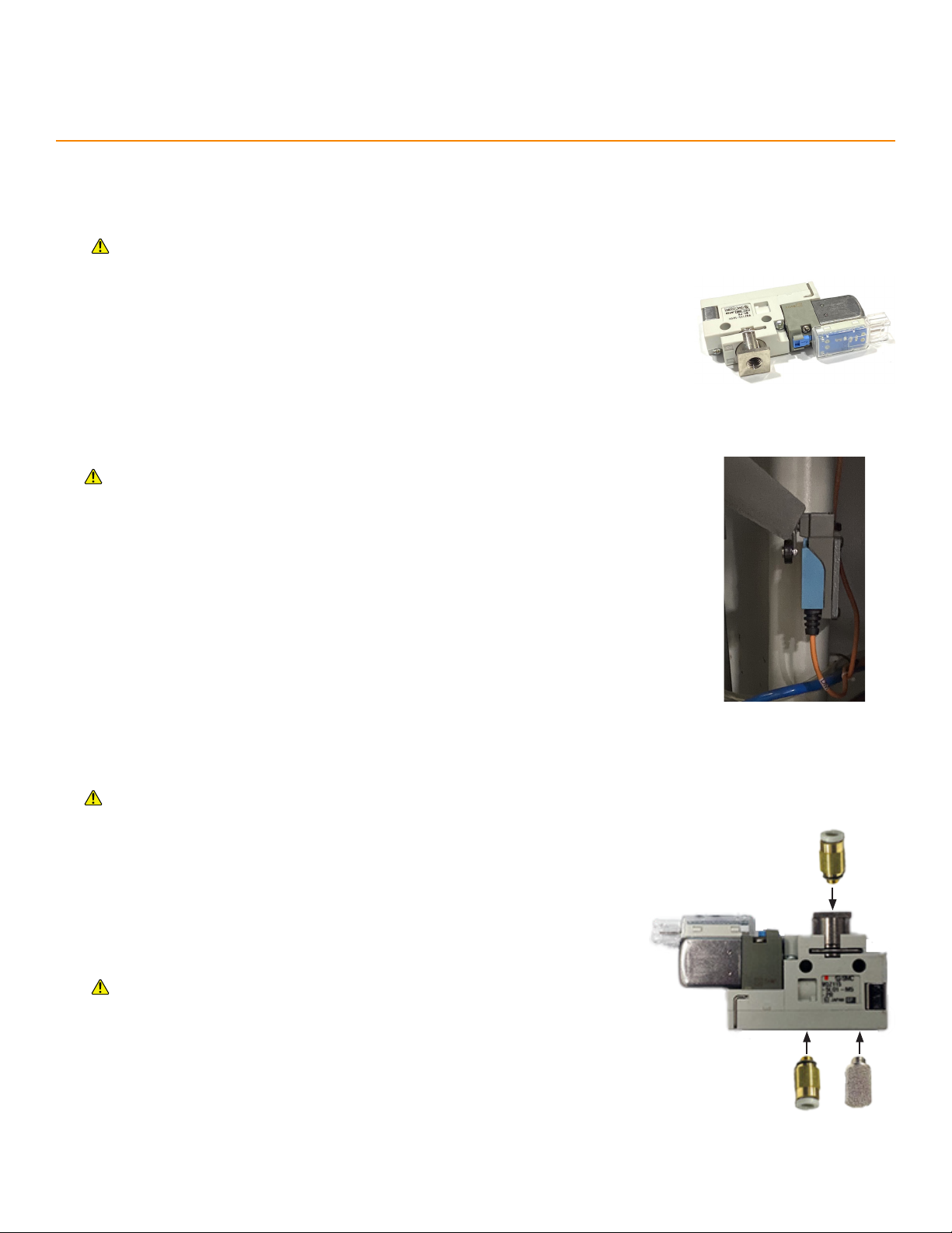
air Solenoi d fu ncTi o n
The air solenoid cuts the tool’s air supply when TigerStop is in motion.
liMiT SwiTcH in STallaTio n
• Mount the Limit Switch to the tool.
* A suitable mounting location causes the Limit Switch to close when
the tool is at rest and to open when the tool is cycling.
* Make sure the SIK cable can reach the Amplifier.
* Drill and tap, as required.
Lockout/Tagout the tool and TigerStop before installation.
• TigerStop in Motion: Closes the Air Solenoid and the tool cannot move.
• TigerStop at Rest: Opens the Air Solenoid and the tool is free to move.
air Solenoi d in STa ll aTi o n
1. Determine which of the tool’s air lines is the “IN” line.
2. Disconnect the “IN” line, and measure it’s outside diameter. If the
diameter is neither 6mm nor 4mm, supply the appropriate sized M5
fittings for the air line.
3. Attach the appropriate M5 fittings and Exhaust Muer to the Air
Solenoid.
Before proceeding to the next step, ensure the SIK cable can reach the
Amplifier and the Red & Black wires’ plug can reach the desired Air
Solenoid location.
4. Cut the tool’s “IN” air line and attach the supply side to the Air
Solenoid’s intake, next to the Exhaust Muer. Attach the tool side to the
outflow on the opposite side of the Air Solenoid.
5. Connect the Red & Black wires’ plug on the SIK cable to the Air
Solenoid.
Lockout/Tagout the tool, TigerStop, and air supply before installation.
“IN” Air
“OUT” Air
Muffler

11
TigerStop Installation
5.2.
conTroller STand
deS c r ipTion and uS e
The controller stand mounts the standard controller to any support structure.
The controller stand rotates between 0-90° with the base hardware.
aSSeM b lY
1. Place the Controller Stand Base Brackets against the Round Tube and insert two M8x45mm Hex-Head
Screws through all three parts.
2. Fasten the Base Brackets to the round tube with M8 Flange Nuts.
3. Insert one M8x35mm T-bolt through each vertical slot in the Controller Stand Base Brackets. Fasten with
M8 Flange Nuts.
4. Insert the Round Tube into the Square tube and fasten with an M6x14mm Socket-Head Screw.
5. Place the Spacer between the Square Tube’s holes.
6. Connect the Spacer, Top, and Tube with an M8x50mm Hex-Head Screw.
7. Fasten with an M8 Flange Nut.
8. Attach the TigerStopStandard Controller to the Controller Stand Top using an M6x10mm Socket-Head
Screw.
9.
1. 3. 4.
6. 7. 8.

12
1. Connect the Data Cable to the TigerStop®Standard Controller and to the Motor Box.
The Data Cable is proprietary. Using an “o the shelf” cable may damage the TigerStop.
2. Connect the Standard Interconnect Kit cable to the Motor Box.
3. Connect the Power Cable to the Motor Box and to incoming power.
final connecTionS
cab le ro uTing
When routing cables, adhere to a few guidelines:
• Keep data cables and power cables separate.
• Keep cables away from dust collection systems.
• Keep cables away from florescent lighting.
• Keep data cables away from any electrical noise generating devices.
• Do not overtighten any zip ties or other cable management restraints.
• Ensure all cables are routed so that they will not become crushed or pinched.
TigerStop Installation
13
HoMe rouTine
Every time TigerStop powers-on, it requires the ‘Home Routine’. The Home Routine is a three-step process in
which TigerStop moves to its farthest possible position.
Ensure the area is clear. TigerStop moves automatically during this routine.
1. Press to run the Home Routine.
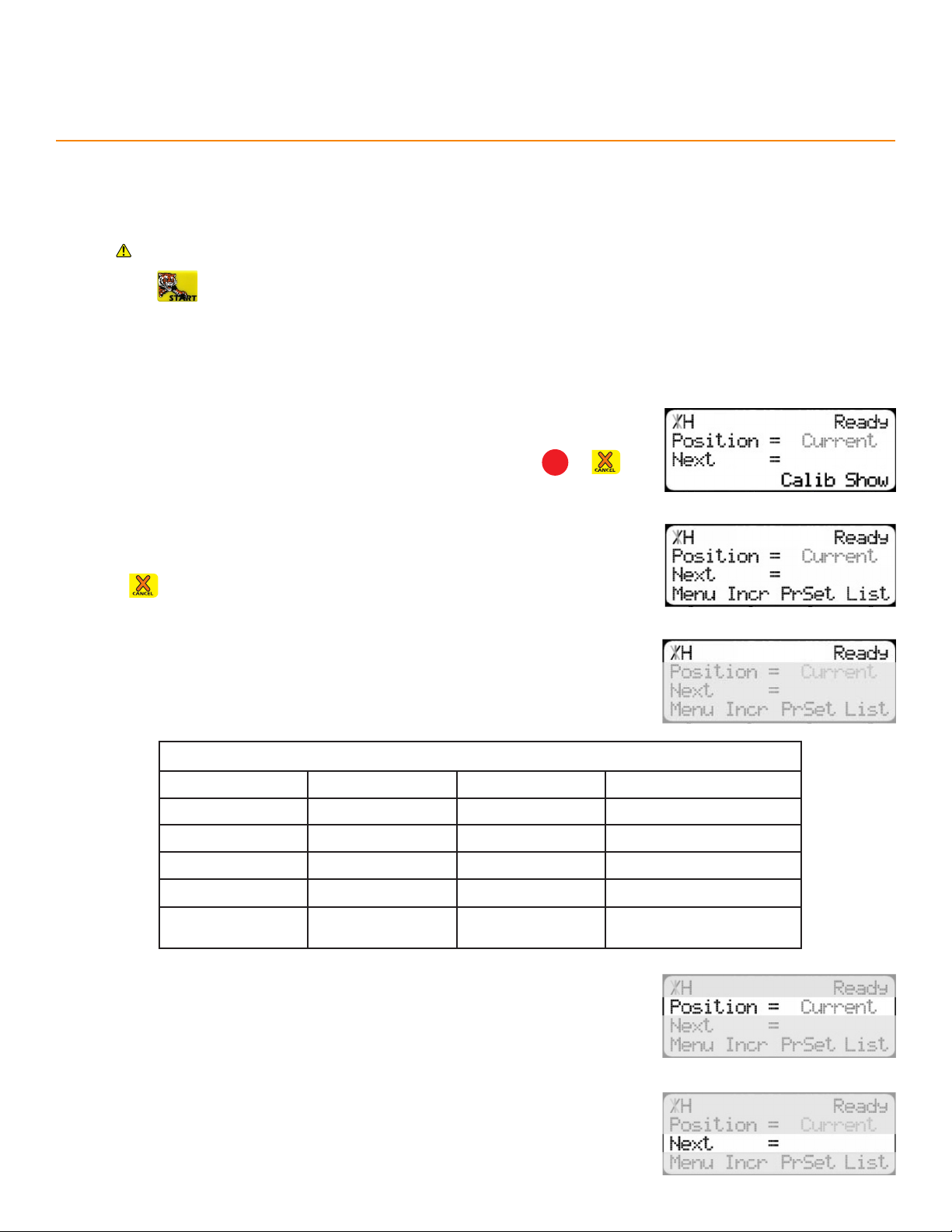
2. When movement stops, the TigerStop®controller displays the Ready Screen.
Line 1 displays the “heartbeat”. The heartbeat is a line that rotates and
indicates that the TigerStop®is functioning normally. The letter next to
the heartbeat is the drive indicator. The drive indicator communicates the
motor’s status.
Line 2 shows the current position of the TigerStop®. The position ends with
either ‘in’ or ‘mm’ depending on measurement system.
Drive Indicator
HHolding Still WWaiting
AAccelerating XDrive Disabled
CConstant Speed NCommunication Error
DDecelerating SStopping
LLash JJog
TWaiting for Text
Entry --- ---
readY Screen
Line 3 shows the next position of the TigerStop®. This is also where user
input appears.
The Ready Screen is the starting point for all TigerStop functions.
The Ready Screen is always accessible by repeatedly pressing STOP or
The Ready Screen has two forms. From the basic Ready Screen, press the
[Show] soft key to display the expanded options.
Press to return to the basic Ready Screen.
Setup

14
Line 4 displays the soft key prompts. These prompts determine what the
soft keys below them do. These change when accessing dierent screens.
Setup
1. From the Ready Screen, press the [Show] soft key.
2. Press the [Menu] soft key.
3. TigerStop requires a password to access all menu options. Enter the
password and press
• By default, the TigerStop password is the serial number.
4. At the Menu Select screen, press
5. Press the [SysInfo] soft key.
SeT Zero end
If the motor box is installed away from the tool, follow these instructions to change the zero end. This tells the Tiger-
Stop to measure in the correct direction. Otherwise, skip this section.
6. Press until reaching the Set Z.E. screen.
7. Press to begin.
8. Press or to toggle the Zero End.
9. Press , then follow the screen prompts to complete the Home
Routine.
Table of contents


