manuals.online logo
Brands
  1. Home
  2. •
  3. Brands
  4. •
  5. Tigo
  6. •
  7. Control Unit
  8. •
  9. Tigo TS4-F Datasheet

Tigo TS4-F Datasheet

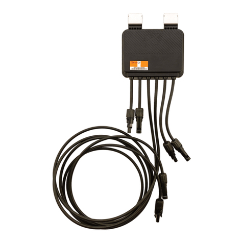
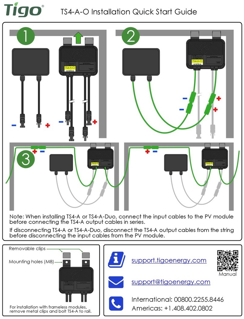
TS4-F Installation Quick Start Guide
· Note: When installing TS4-R-F, connect the input cables to the PV module before connecting
the TS4-R-F output cables in series.
· If disconnecting TS4-R-F, disconnect the TS4-R-F output cables from the string before disconnecting
the input cables from the PV module.
·RSS transmitter must be powered off during TS4-F or TS4-R-F installation.
1
3
2
TS4-F (Integrated)
TS4-R-F (Add-on/Retrot)
03/05/2019002-00061-00
· Drill holes in enclosure for conduit (see drilling guide for placement)
· Mount RSS Transmitter and power supply on DIN rail
· Connect DC leads from power supply (1) to transmitter (2)
· Connect RSS Core (3) to transmitter
Note: Install TS4-F before powering on RSS Transmitter
Transmitter power supply must be on same AC branch circuit as inverter
to meet rapid shutdown requirements.
RSS Transmitter Installation
NN
LL
-
+
RSS
Transmitter
1 2
3
RSS Core inputs
LED (Signal)
LED (Power)
+VIN
GND
3 RSS Core (CT)
1 DIN Rail PSU
2 RSS Transmitter
3
1 2
Place rapid shutdown system label no more than 1m (3ft) from RSS Transmitter
or AC disconnect if not at same location.
01/14/2018002-00061-00
85-264VAC PSU
· Pass either positive or negative homerun through RSS Core
· Connect wires to AC side of power supply
Note: Install TS4-F before powering on RSS Transmitter
RSS Transmitter Wiring
NN
LL
-
+
RSS
Transmitter
Homerun
Only (+) or (-)
through RSS Core
AC Wires for
Power Supply
Max number of strings per RSS Core: 10
Max string length: 30 modules
Max current per RSS Core: 100A
Max cable length from inverter (+) to inverter (-): 1000ft (300m)
85-264VAC PSU
· Connect AC and DC ground wires to DIN rail
· Ground all conduit connections
· Turn on AC power to Transmitter power supply to activate
keep-alive signal and energize PV array
Note: Install TS4-F before powering on RSS Transmitter
RSS Transmitter Grounding
Warning: nonmetallic enclosure does not provide bonding between
conduit connections. Use grounding type bushings and jumper wires.
NN
LL
-
+
RSS
Transmitter
Conduit Ground
AC Ground
DC Ground
85-264VAC PSU
Note: Install TS4-F before powering on RSS Transmitter
Transmitter power supply must be on same AC branch circuit as inverter
to meet rapid shutdown requirements
RSS Transmitter Dual Core Installation
· Drill holes in enclosure for conduit (see drilling guide for placement)
· Mount RSS Transmitter and power supply on DIN rail
· Connect DC leads from power supply (1) to transmitter (2)
· Connect RSS Core (3) and (4) to transmitter
3 4
1 2
NN
LL
-
+
1 DIN Rail PSU
2 RSS Transmitter
3
4
RSS Core (CT)
RSS Core (CT)
RSS Core inputs
RSS Core inputs
LED (Signal)
LED (Power)
+VIN
GND
RSS
Transmitter
1 2
3
4
Place rapid shutdown system label no more than 1m (3ft) from RSS Transmitter
or AC disconnect if not at same location.
85-264VAC PSU
RSS Transmitter Dual Core Wiring
NN
LL
-
+
RSS
Transmitter
· Pass either positive or negative homerun through RSS Cores
· Connect wires to AC side of power supply
Note: Install TS4-F before powering on RSS Transmitter
Homerun
Homerun
AC Wires for
Power Supply
Only (+) or (-)
through RSS Core
Max number of strings per RSS Core: 10
Max string length: 30 modules
Max current per RSS Core: 100A
Max cable length from inverter (+) to inverter (-): 1000ft (300m)
85-264VAC PSU
RSS Transmitter Dual Core Grounding
NN
LL
-
+
RSS
Transmitter
Conduit Ground
AC Ground
DC Ground
· Connect AC and DC ground wires to DIN rail
· Ground all conduit connections
· Turn on AC power to Transmitter power supply to activate
keep-alive signal
Note: Install TS4-F before powering on RSS Transmitter
Warning: nonmetallic enclosure does not provide bonding between
conduit connections. Use grounding type bushings and jumper wires.
85-264VAC PSU
2X Ø 28
108
47.1
41.6
Ø 28
47.1
41.6
2X Ø 28
40
47.1
41.6
3X Ø 28
40
47.1
68
41.6
41.6
104.5
50.6
2X Ø 35
41.6
50.6
Ø 35
41.6
41.6
52.3
52.3 52.3
50.6 50.6
3X Ø 35 2X Ø 35
*all dimensions in mm
Enclosure Drilling Guide for .75" Conduit
Single Core Dual Core
Enclosure Drilling Guide for 1" Conduit
TS4-F/TS4-R-F:
·Output voltage without active transmitter signal is 0.6V
·Output voltage with active transmitter signal will be normal
module VMP or VOC
·If output is 0V contact Tigo support
Check that the system conforms to the design rules
for TS4-F:
·Up to 10 strings per RSS Core (CT)
·Up to 30 modules per string
·String length up to 1000ft (total cable length from +to -)
·Homeruns through RSS Core must be the same polarity
(all positive or all negative)
RSS Transmitter:
·Power LED should be lit and Signal LED should be blinking
during operation
·Verify that RSS Core wiring is correct
·Power cycle RSS Transmitter if Signal LED is unlit
·While RSS Transmitter is powered off, string voltage should be
(0.6V * number of modules)
·While RSS Transmitter is powered on, full string voltage should
be present
Test individual strings with active RSS Transmitter
one at a time in case of unexpected voltage.
Troubleshooting TS4-F and RSS Transmitter

Other manuals for TS4-F

3

This manual suits for next models

1

Other Tigo Control Unit manuals

Tigo TS4 UHD-Core User manual

Tigo

Tigo TS4 UHD-Core User manual

Tigo TS4-A-2F Datasheet

Tigo

Tigo TS4-A-2F Datasheet

Tigo TS4-A-O Datasheet

Tigo

Tigo TS4-A-O Datasheet

Popular Control Unit manuals by other brands
GRASS VALLEY KAMELEON Series instruction manual

GRASS VALLEY

GRASS VALLEY KAMELEON Series instruction manual

Buderus MP100 EMS plus installation instructions

Buderus

Buderus MP100 EMS plus installation instructions

Emerson PACSystems RX3i quick start guide

Emerson

Emerson PACSystems RX3i quick start guide

Macnaught HG 55 Series instruction manual

Macnaught

Macnaught HG 55 Series instruction manual

Denon RC-7000CI - Remote Control - Infrared/radio owner's manual

Denon

Denon RC-7000CI - Remote Control - Infrared/radio owner's manual

Watts AMES 930GD Installation, operation and maintenance manual

Watts

Watts AMES 930GD Installation, operation and maintenance manual

Synatel DML4AI operating instructions

Synatel

Synatel DML4AI operating instructions

Lutron Electronics GRAFIK Eye QSGRJ-8E Programming Addendum

Lutron Electronics

Lutron Electronics GRAFIK Eye QSGRJ-8E Programming Addendum

Stahl ConSig 8040 Series operating instructions

Stahl

Stahl ConSig 8040 Series operating instructions

Tektronix TLA7B Series Service manual

Tektronix

Tektronix TLA7B Series Service manual

M-system R7ML-DC16D instruction manual

M-system

M-system R7ML-DC16D instruction manual

Unitronics V100-17-RS4 quick start guide

Unitronics

Unitronics V100-17-RS4 quick start guide

Akron Brass Style 8840 Instructions and parts list

Akron Brass

Akron Brass Style 8840 Instructions and parts list

Asus AAEON COM-WHUC6 user manual

Asus

Asus AAEON COM-WHUC6 user manual

ZTW Gecko Series user manual

ZTW

ZTW Gecko Series user manual

S.R.Smith WPC1-T Series installation instructions

S.R.Smith

S.R.Smith WPC1-T Series installation instructions

Prodigy P2 installation guide

Prodigy

Prodigy P2 installation guide

biawar ME 0040 Installation and operating manual

biawar

biawar ME 0040 Installation and operating manual

manuals.online logo
manuals.online logoBrands
  • About & Mission
  • Contact us
  • Privacy Policy
  • Terms and Conditions

Copyright 2025 Manuals.Online. All Rights Reserved.